Introduction to procedural animation
In this series of articles we will introduce inverse kinematics in video games. Before we begin our journey, I’ll talk about a few games that use procedural animations and how they differ from traditional resource-based animations.
Gif
The series will consist of the following parts:
')
- Part 1. Introduction to procedural animation
- Part 2. Mathematics of direct kinematics
- Part 3. Realization of direct kinematics
- Part 4. Introduction to Gradient Descent
- Part 5. Inverse kinematics for a robotic arm
- Part 6. Inverse kinematics of tentacles
Part 7. Inverse kinematics of spider legs
Part 1. Introduction to procedural animation
In most games, character animations are “static.” When a character moves on the screen, the artist creates a specific movement. They are handcrafted or recorded using motion capture. Animations in this case are pre-created resources . When a character needs to perform another action, another animation is required. This way of implementing character movement is fairly standard for the games industry. There are large and detailed collections of animations in which there are the most commonly used behaviors, such as walking, jumping, and shooting. Traditional animations dominate the gaming industry, but they have equivalent alternatives. I want to introduce you to the concept of procedural animations .
The main idea here is that the moments of the character's state can be generated procedurally. In one of the most standard techniques for generating procedural animations, physics simulation is used. Therefore, it is often called physical animation ( Wikipedia ). A typical example is water. You can animate it manually or use animation that takes into account the dynamics of liquids .
Below we will discuss a very specific subtype of physical animations in which rigid body simulation is used. The same type of simulation is commonly used in game engines, such as Unity and Unreal. Let's see how this simple principle is used in games to create physical animations.
Ragdoll physics
At the very basis of physical animations lies the principle of the possibility of simulating the movement of characters. By recreating the processes and limitations that govern the human body, one can get closer to creating realistic behaviors. One of the simplest but effective ways to create procedural animations is the use of ragdoll physics (ragdoll, ragdoll) ( Wikipedia ). The idea is to create a humanoid body and connect all its links with joints to recreate the degrees of freedom demonstrated by the real prototype. Just using the physics of solids and limiting joints, you can simulate the fall of the human body. This not only allows you to save money on the "death animation". It also allows you to create characters that fall realistically and interact with environments. Such a task is almost impossible to solve with the help of only a ready-made set of animations, regardless of its accuracy.
The biggest drawback of Ragdolls is their huge unpredictability, which often leads to very funny behaviors.
Gif
Today, ragdolls are very familiar in games. Unity has a simple Ragdoll Wizard tool that allows you to quickly turn a humanoid model into a ragdoll.
Solid body simulations
The main problem of ragdolls is the lack of motion control. If you connect parts of the body with joints, the character can neither walk nor jump. He will only fall. However, there are situations in which a mixed approach can be used.
In a How Grow Home Uses Maths To Generate Personality article, game journalist Alex Wiltshire (Alex Wiltshire) talks with Ubisoft representatives about the game Grow Home . One of the main features of the game is the way the main character moves, Bud (BUD). The game has no ready-made animations, at least in the traditional sense. When a player moves, the position of the legs and arms is controlled by a code. Parts of the body are subject to the same restrictions as Ragdoll, which causes them to create compelling animations.
A similar principle is also widely used in Rain World . Each animal in the game has a body consisting of several colliders. Some of them are controlled by code, others are controlled by joints. This can be seen in the animation below. The end points of the wings of a bird of prey move programmatically, the remaining bones are connected by hinges. Endpoint control automatically creates a smooth animation that you could not otherwise achieve.
Gif
In both Grow Home and Rain World, procedural animations are used to increase the realism of the characters. However, controllers do not rely on these animations. In the game Gang Beasts, this concept is developed even further. The game fully approves of loose movements resulting from the use of ragdoll physics. The result was funny characters with unpredictable movements.
Gif
Inverse kinematics
Simulations of a rigid body allow you to simplify the creation of animations. We indicate where the hands and legs of Bud should be, and the physics engine does the rest. This very simple approach works with simple characters, but it often lacks realism. In simulations of a solid body, only parameters such as gravity and mass are taken into account, but they lack knowledge of the context. In many cases, it is required to create something that acts not only under the influence of restrictions caused by gravity and connections.
The next step in creating procedural animations is known as inverse kinematics . For any type of ragdoll, inverse kinematics calculates how to move it to achieve the desired goal. In Grow Home and Rain World, physics itself determines how gravitated compounds should move. Inverse kinematics makes them move in the right phases.
One of the first indie games in which this concept was actively used was The Majesty Of Color Studio Future Proof Games . In it, the player controls the tentacle of the sea creature. Unlike the wing of the bird from the Rain World, this tentacle is not just driven by hinges. Each segment is rotated so that the end point of the tentacle reaches the desired point. If only a rigid body simulation was used in this animation, then the tentacle would seem to be “pinned” to this point, like a piece of rope.
Gif
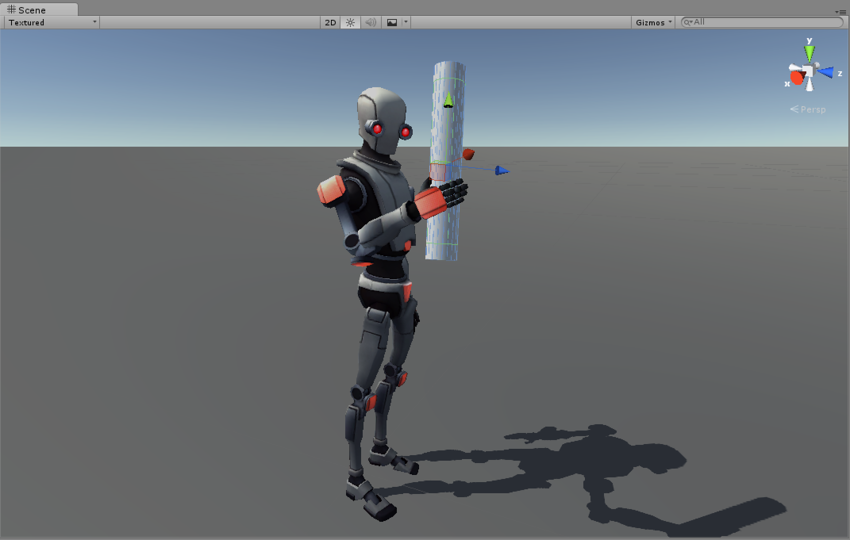
Inverse kinematics can be used to solve a variety of problems. The most standard is the natural movement of humanoid characters to certain objects. Instead of using pre-defined animations, the developers simply indicate the goal that the hand must achieve. All the rest is done by inverse kinematics, which finds the most natural way of moving the joints of the hand. If only a rigid body simulation was used, then the movement would be convulsive, it would seem that parts of the body are simply being dragged.
In the Unity animation editor called Mechanim there is a tool ( Unity help ) that allows the developer to use inverse kinematics for humanoid characters.
In the rest of this series of articles, I will focus on solving the problem of inverse kinematics. We will figure out how you can control a robotic arm or a monster's tentacle.
Gif
Part 2. Mathematics of direct kinematics
Now we begin the journey into the world of inverse kinematics . There are many ways to solve this problem, but they all start with direct kinematics .
Inverse kinematics takes a point in space and tells us how to move your hand to reach it. Direct kinematics solves the opposite dual problem. Knowing how we will move our hand, she tells us which point in space the hand will reach.
Robotic arm
Inverse kinematics was originally used to control robotic arms . Therefore, in this series of articles will be used assumptions and terminology of robotics. However, this does not limit the possible applications of inverse kinematics. You can use it for human hands, paws, spiders and tentacles.
First, let's start with a demonstration of what we understand by the term “robot manipulator”:
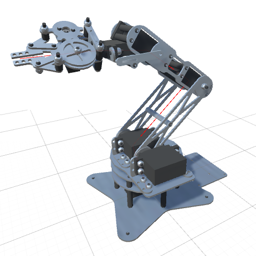
The image above shows a standard robotic arm made from “links” (limbs) connected by “joints” (joints). Since the robot shown in the image has five independent joints, it is believed that it has five degrees of freedom . Each joint is controlled by the engine, allowing you to move the link attached to the joint at a certain angle.
To consider a more general example, we can draw a joint scheme. In this article, we will assume that each joint can only rotate along one axis.
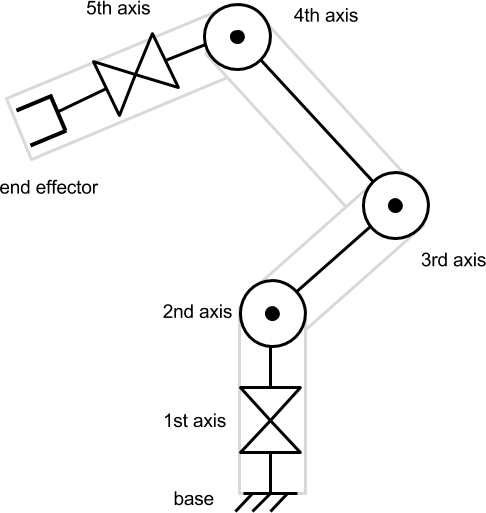
A tool attached to the end of a robotic arm is called an end link . Depending on the context, it may or may not be considered one degree of freedom. In this article, the final link will not be taken into account, because we will focus only on the movement to reach the desired point.
Direct kinematics
In this example, each joint can rotate along one axis. Therefore, the state of each joint is measured as an angle. By turning each joint at a certain angle, we allow the end link to reach different points in space. Determining where the final link is located at known angles of articulation is called direct kinematics .
Direct kinematics is a “simple” problem. It means that for each set of angles there is one single result that can be calculated without any uncertainties. Determining how the robotic arm moves depending on the data we transmit is a necessary step to find the inverse problem of inverse kinematics.
Geometric interpretation
Before we start writing code, we need to understand the mathematical constructions behind the direct kinematics. But first of all we need to understand what it means spatially and geometrically.
Since it’s not so easy to visualize turns in 3D, let's start with a simple manipulator in 2D space. The robot arm has a “starting position” - this is a configuration in which all the joints are turned at their “zero angle”.
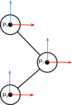
The diagram above shows a manipulator with three degrees of freedom. Each joint is turned to the position of its zero angle, that is, the robot is in the initial position. We can see how this configuration changes when the articulation is turned.
 on
on  degrees It leads to the corresponding movement of the whole chain of joints and links attached to .
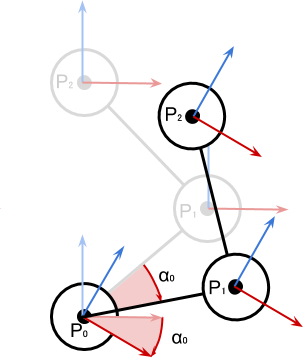
It is important to note that the engines attached to the other joints have not moved yet. Each joint contributes to the local rotation of a straight chain of links. The diagram below shows the configuration change when turning the second joint on
 degrees
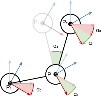
Position
 determines only and on
  impact already and and . The coordinate coordinate system (red and blue arrows) is oriented according to the sum of the turns of the earlier chain of connections to which it is attached.
Maths
From the previous schemes it is obvious that in order to solve the problem of direct kinematics, we need to calculate the position of the nested (subordinate) objects during their rotation.
Let's see how to calculate it on the example of two joints. Having found a solution for two elements, we can repeat this process to solve chains of any length.
Let's start with the simple case when the first joint is in its initial position. It means that
 as in the diagram below:
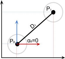
It means that:
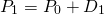
When
not zero, we just need to rotate the distance vector at the pivot point  around on degrees:
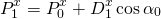
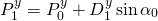
Mathematically, this can be written as:

Below we will learn how to use the
AngleAxis function ( Unity documentation ) without AngleAxis around with trigonometry.Reproducing the same logic, we can get an equation for
:
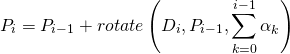
And finally, the general equation:
In the next part of the article, we will see how this equation is conveniently implemented in C # code.
Direct kinematics in 2D
If you are familiar with rotation in 2D, then this can be done trigonometrically:
About the derivation of the equation can be read in my article A Gentle Primer on 2D Rotations .
About the derivation of the equation can be read in my article A Gentle Primer on 2D Rotations .
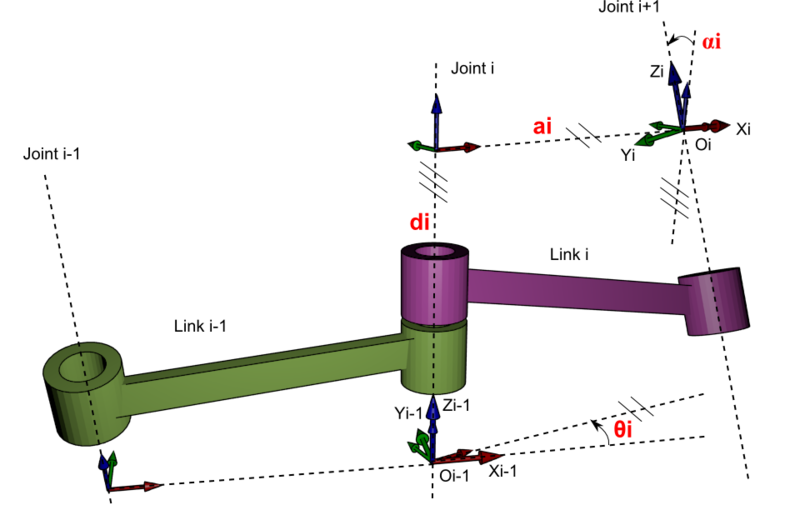
What about the Denavit-Hartenberg matrix?
If you have engineering knowledge, you could solve this problem differently. The problems of direct and inverse kinematics are widely known, and there are several standardized approaches to solve them. One of them is binding to each joint of four parameters, called Denavit-Hartenberg parameters ( Wikipedia ). It is convenient to work with them in a matrix format and they are excellently suited for analytically solving the problem of inverse kinematics.
However, in this article we do not use them. Solving the Denavit-Hartenberg matrix requires more math than many programmers want to understand. The approach I have chosen uses gradient descent , which is a more general optimization algorithm.
However, in this article we do not use them. Solving the Denavit-Hartenberg matrix requires more math than many programmers want to understand. The approach I have chosen uses gradient descent , which is a more general optimization algorithm.
Part 3. Realization of direct kinematics
In this part we will continue to solve the problem of direct kinematics . Having found the mathematical solution in the last part, now we will learn how to implement it in C # code for Unity. In the next part, “Introduction to Gradient Descent,” we finally show the theoretical rationale for solving the problem of inverse kinematics .
Introduction
In the previous section, we formalized the movement of a robotic arm. We started with a simple example of three joints. In their initial positions, they have the configuration shown below:
Various
 The diagram represents Cartesian coordinates, or
  -th joint. Local angles defining rotation relative to the starting positions are labeled as
  .
.When turning the joints, we see the following picture:
The behavior of this system can be summarized by the following statements:
- Rotate Global twist
 articulations are the sum of the turns of all previous articulations:
- Position Global position articulation is given as:
In view of the foregoing, we can begin to invent a possible way to implement these behaviors in Unity.
GameObject Hierarchy
In Unity, there is already a way to implement all of the above requirements: parenting . If you make a game object a child of another, it automatically inherits position, rotation, and scale.
If rigging is familiar to you, it will not surprise you. The bones, which are the joints of a humanoid character, also have a parental system, in which turns and movements are inherited. The image from Unity Animation 3: Character Setup by Michael Erbetnot shows an obvious example of this.
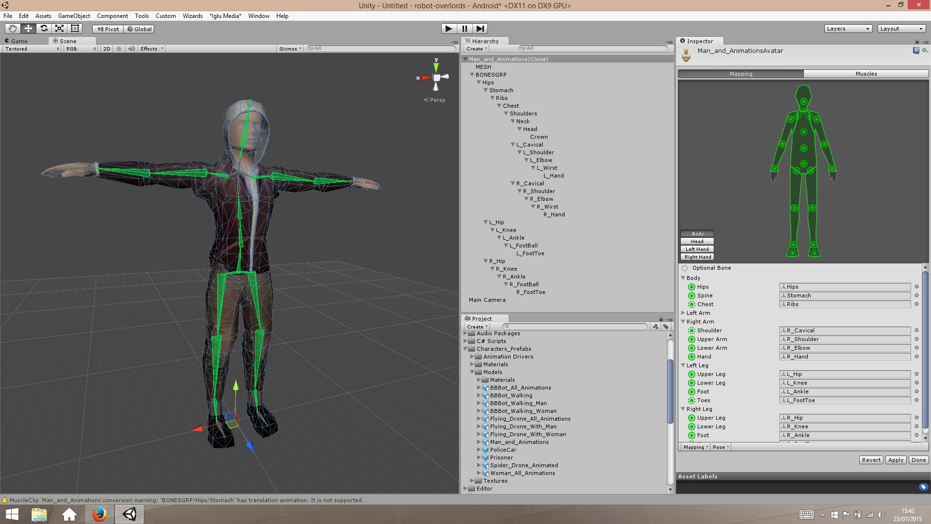
When creating a hierarchy of connections, it is necessary to make sure that when all local Euler angles are zero, the robot arm is in the initial position. For a humanoid character, this is usually the standard T-shaped pose shown in the image above.
Implementation
The ability to create child components in Unity de facto solves the problem of direct kinematics. Unfortunately, this is not enough. In the next part of the series of articles we will see that we really need a way to check the position of the final link without moving the robotic arm. This will force us to implement this basic Unity feature in our own way.
The first step is to save information about each of the joints of the robot arm. This can be achieved using a script, for example
RobotJoint from the following example: using UnityEngine; public class RobotJoint : MonoBehaviour { public Vector3 Axis; public Vector3 StartOffset; void Awake () { StartOffset = transform.localPosition; } } To simplify the calculations, we assume that each joint can only rotate along its own local axis: X, Y, or Z. We denote this by the variable
Axis , which takes the value 1 for the coordinate relative to the axis of rotation. If the joint rotates along the Y axis, then Axis will look like (0,1,0) . We will see how this allows us to get rid of constructions with IF .Let's create the
ForwardKinematics function. It gets an array of angles float numbers. The name speaks for itself: angles[i] contains the value of the local rotation of the ith joint. The function returns the position of the final link in global coordinates. public Vector3 ForwardKinematics (float [] angles) { ... } The code is a simple C # implementation of the above position equation. The
rotate functions are implemented through the convenient Quaternion.AngleAxis function. Vector3 prevPoint = Joints[0].transform.position; Quaternion rotation = Quaternion.identity; for (int i = 1; i < Joints.Length; i++) { // rotation *= Quaternion.AngleAxis(angles[i - 1], Joints[i - 1].Axis); Vector3 nextPoint = prevPoint + rotation * Joints[i].StartOffset; prevPoint = nextPoint; } return prevPoint; Need help with quaternions?
Turns in Unity are often described through Euler angles. These are three numbers that correspond to the rotation of an object along the X, Y, and Z axes. Euler angles denote roll (roll) , pitch (pitch), and yaw (yaw) of the object in space. However, from a mathematical point of view, using Euler angles can lead to rather unpleasant problems.
Working with corners is more convenient with quaternions . Quaternions are mathematical objects that can be used to describe turns . In contrast, Euler angles describe the orientation . Quaternion describes the path that you need to go from one orientation to another. From a technical point of view, this is too great a simplification, but for our article it is more than enough.
Quaternion can be represented as a turn. The rotation of an object in space is, from a mathematical point of view, an analogue of multiplying its position by a quaternion. You can use the
When multiplying two quaternions, a new quaternion is created, which includes both rotations. At each iteration of the
Finally, quaternions are used in this line:
It fully corresponds to the following entry:
The product of a quaternion and a vector applies rotation.
Working with corners is more convenient with quaternions . Quaternions are mathematical objects that can be used to describe turns . In contrast, Euler angles describe the orientation . Quaternion describes the path that you need to go from one orientation to another. From a technical point of view, this is too great a simplification, but for our article it is more than enough.
Rotations ⇔ Quaternions
Quaternion can be represented as a turn. The rotation of an object in space is, from a mathematical point of view, an analogue of multiplying its position by a quaternion. You can use the
Quaternion.AngleAxis function to create a rotation around a fixed point in Unity. String Quaternion.AngleAxis(angle, axis); creates a quaternion that describes the rotation around the axis axis by angle degrees. In this context, the value of Axis can be (1,0,0) , (0,1,0) or (0,0,1) , which means, respectively, X, Y or Z. This explains why we created the variable Axis in the RobotJoint class.Adding rotations multiplication of quaternions
When multiplying two quaternions, a new quaternion is created, which includes both rotations. At each iteration of the
for loop, the rotation variable is multiplied by the current quaternion. This means that it will include all the turns of all joints.Quaternion * vector = rotated vector
Finally, quaternions are used in this line:
Vector3 nextPoint = prevPoint + rotation * Joints[i].StartOffset; It fully corresponds to the following entry:
The product of a quaternion and a vector applies rotation.
[Ending follows. In the second article, we will look at inverse kinematics.]
Source: https://habr.com/ru/post/332164/
All Articles