Another example of asynchronous circuit synthesis: VME bus controller
I looked through the book recently (not all, only what was allowed):
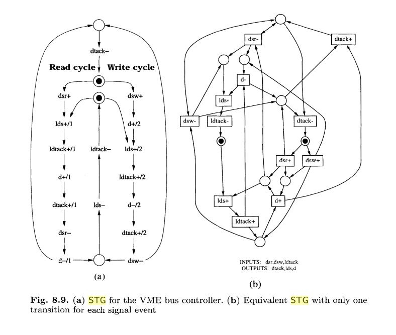
Found an example of how to make schemes with Petrify. The original task looks like this:
')
As a result, we got this SI scheme:
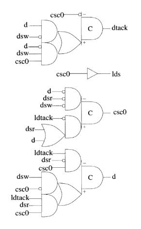
Yes, they didn’t go far away from Muller, but C-elements were just hung up. I think, all the same it is necessary to show how to do asynchronous circuits. For a start, better get to know this.
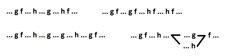
And here I will analyze the given example. To begin with, I draw the initial behavior more comfortably and replace the long names of the signals:
dsr - a
dsw - b
ldtack - c
lds - x
d - y
dtack - z
To synthesize the SI scheme on two-input elements, it is necessary to supplement the original behavior with new signals so that each non-input signal (f) can be entered into one of the following patterns (or their combination):
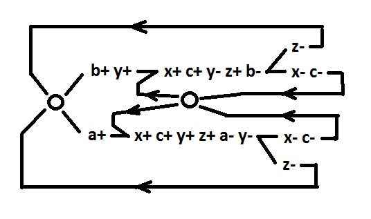
To understand how to use patterns in relation to behavior with a choice, consider the behavior consisting of two alternative branches. And then we will consider the behavior of the same two branches, but located one after the other.
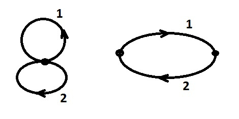
It is easy to verify that the logical functions for both of these behaviors are the same. This is understandable, the second behavior is the same as the first, only with a fixed discipline of switching the input signals. Accordingly, in order to use a pattern as applied to a behavior with a choice, it is necessary to successively at least once go through all branches in an arbitrary order (but only one that admits the original task). And one more note: additional signals will be inserted without fixing the mark. Signs will be placed at the very end.
So, look at the original behavior. The problem that needs to be solved in the first place: the choice occurs simultaneously with the parallel branch x-c-. You must synchronize this branch. Bearing in mind the further fragmentation of behavior, it is better to do synchronization separately for each alternative branch. along with isolating the signal c.
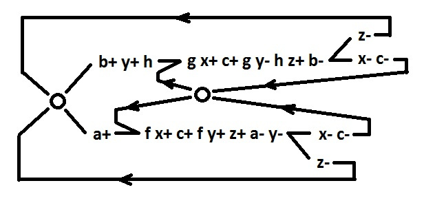
The added signal f fits into the pattern (i.e., has a two-way implementation) using the existing signals (f = ac). The g signal could be written into the template using the y and c signals, but it is better to add the h signal, which can later be used to isolate the y signal. Signals f, g are declared pseudo input, i.e. we prohibit them from placing new signals (in order not to spoil the two-way implementation).
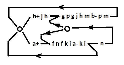
The studied behavior is clearly divided into two alternative branches. Therefore, it can be divided into two independent behaviors, each of which will be one of the alternative branches. To do this, isolate the signals found in both branches. To isolate the signal x means to get a two-way implementation (enter in the template) for this signal x and for all signal-effects (signals whose switching is the result of switching the signal x). Thus, we eliminate the influence of the signal x on the circuit and then we can not consider it.
Common to both branches are signals - c, x, y, z. The c signal is input, does not require implementation. Its corollaries f, g are already implemented. The consequences of the x and z signals are input signals; they do not require implementation. For the consequences of the signal y, we use h and the new signal i (h = yb, i = yb). Signals h and i are now pseudo input. To implement the signal y, we insert the new j and k (y = jk). Signal z is implemented using the already existing signal i and the new signal m (z = im). To implement the signal x, add new signals n and p (x = np). The signals y, z, x are now pseudo-input.

Remove isolated signals from the graph. The actions are the same as when adding a signal, only the sequence is reversed. The reason for removing signals is the following: to synthesize a scheme for behavior with isolated signals, it is sufficient to construct a scheme for the same behavior, but with remote isolated signals.
Signals a, b - input, f, g, h, i - pseudo input.
To synthesize a circuit for such behavior (with unique signals in each branch), it is enough to synthesize two schemes for each alternative branch separately. The fact that the n branch is parallel to the selection point is not an obstacle, since This branch is synchronized by the pseudo input signal g.
Consider separately the upper branch.
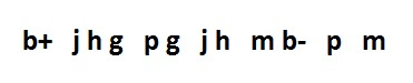
Signals b, g, h - input or pseudo input.
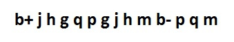
Consider readiness for decomposition. There are no violations of CSC. The m signal already has a two-way implementation (m = ph). For signal j, the signal g can be used as a dual signal. For the signal p, it is necessary to add a dual signal q.
Now we find the logical functions. While the signs are not placed - the form of the function is conditional.
m = qh
p = bq
q = gp
j = g + bp or j = g + bq
We decompose j (thereby introducing a new signal r).
j = rg
r = bp or r = bq
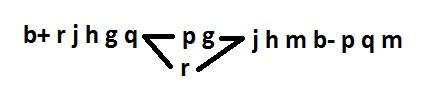
Remember that r can be a consequence of p (instead of - q). This can be useful when placing characters.
Now consider separately the lower branch.
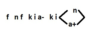
Signals a, f, i - input or pseudo input.
There are violations of CSC. These are the sequences: nfnf and ki a- ki a +. Eliminated by the only possible way (signal s).
Signals n, k already have a two-way implementation (n = si, k = fs). For signal s, dual signal t is required.

Now logical functions look like this:
n = ti
r = fs
s = ft
t = as
For both alternative branches, all signals are reduced to realizability in a two-input basis. Now restore the behavior in full, with all added signals.
Finally, we will arrange the signs. The resulting discrepancies of inputs for signals i, f, q, p, n are corrected by adding inverters v, w, u, d, e, respectively.
But the logical functions for all signals.
The scheme looks like this:
I counted transistor pairs. Deafening superiority failed. 78 to 94, if not mistaken. Anyway. I tried in vain, or something. I publish.
Found an example of how to make schemes with Petrify. The original task looks like this:
')
As a result, we got this SI scheme:
Yes, they didn’t go far away from Muller, but C-elements were just hung up. I think, all the same it is necessary to show how to do asynchronous circuits. For a start, better get to know this.
And here I will analyze the given example. To begin with, I draw the initial behavior more comfortably and replace the long names of the signals:
dsr - a
dsw - b
ldtack - c
lds - x
d - y
dtack - z
To synthesize the SI scheme on two-input elements, it is necessary to supplement the original behavior with new signals so that each non-input signal (f) can be entered into one of the following patterns (or their combination):
To understand how to use patterns in relation to behavior with a choice, consider the behavior consisting of two alternative branches. And then we will consider the behavior of the same two branches, but located one after the other.
It is easy to verify that the logical functions for both of these behaviors are the same. This is understandable, the second behavior is the same as the first, only with a fixed discipline of switching the input signals. Accordingly, in order to use a pattern as applied to a behavior with a choice, it is necessary to successively at least once go through all branches in an arbitrary order (but only one that admits the original task). And one more note: additional signals will be inserted without fixing the mark. Signs will be placed at the very end.
So, look at the original behavior. The problem that needs to be solved in the first place: the choice occurs simultaneously with the parallel branch x-c-. You must synchronize this branch. Bearing in mind the further fragmentation of behavior, it is better to do synchronization separately for each alternative branch. along with isolating the signal c.
The added signal f fits into the pattern (i.e., has a two-way implementation) using the existing signals (f = ac). The g signal could be written into the template using the y and c signals, but it is better to add the h signal, which can later be used to isolate the y signal. Signals f, g are declared pseudo input, i.e. we prohibit them from placing new signals (in order not to spoil the two-way implementation).
The studied behavior is clearly divided into two alternative branches. Therefore, it can be divided into two independent behaviors, each of which will be one of the alternative branches. To do this, isolate the signals found in both branches. To isolate the signal x means to get a two-way implementation (enter in the template) for this signal x and for all signal-effects (signals whose switching is the result of switching the signal x). Thus, we eliminate the influence of the signal x on the circuit and then we can not consider it.
Common to both branches are signals - c, x, y, z. The c signal is input, does not require implementation. Its corollaries f, g are already implemented. The consequences of the x and z signals are input signals; they do not require implementation. For the consequences of the signal y, we use h and the new signal i (h = yb, i = yb). Signals h and i are now pseudo input. To implement the signal y, we insert the new j and k (y = jk). Signal z is implemented using the already existing signal i and the new signal m (z = im). To implement the signal x, add new signals n and p (x = np). The signals y, z, x are now pseudo-input.
Remove isolated signals from the graph. The actions are the same as when adding a signal, only the sequence is reversed. The reason for removing signals is the following: to synthesize a scheme for behavior with isolated signals, it is sufficient to construct a scheme for the same behavior, but with remote isolated signals.
Signals a, b - input, f, g, h, i - pseudo input.
To synthesize a circuit for such behavior (with unique signals in each branch), it is enough to synthesize two schemes for each alternative branch separately. The fact that the n branch is parallel to the selection point is not an obstacle, since This branch is synchronized by the pseudo input signal g.
Consider separately the upper branch.
Signals b, g, h - input or pseudo input.
Consider readiness for decomposition. There are no violations of CSC. The m signal already has a two-way implementation (m = ph). For signal j, the signal g can be used as a dual signal. For the signal p, it is necessary to add a dual signal q.
Now we find the logical functions. While the signs are not placed - the form of the function is conditional.
m = qh
p = bq
q = gp
j = g + bp or j = g + bq
We decompose j (thereby introducing a new signal r).
j = rg
r = bp or r = bq
Remember that r can be a consequence of p (instead of - q). This can be useful when placing characters.
Now consider separately the lower branch.
Signals a, f, i - input or pseudo input.
There are violations of CSC. These are the sequences: nfnf and ki a- ki a +. Eliminated by the only possible way (signal s).
Signals n, k already have a two-way implementation (n = si, k = fs). For signal s, dual signal t is required.
Now logical functions look like this:
n = ti
r = fs
s = ft
t = as
For both alternative branches, all signals are reduced to realizability in a two-input basis. Now restore the behavior in full, with all added signals.
Finally, we will arrange the signs. The resulting discrepancies of inputs for signals i, f, q, p, n are corrected by adding inverters v, w, u, d, e, respectively.
But the logical functions for all signals.
The scheme looks like this:
I counted transistor pairs. Deafening superiority failed. 78 to 94, if not mistaken. Anyway. I tried in vain, or something. I publish.
Source: https://habr.com/ru/post/331614/
All Articles