Automated programming - a new milestone or myth? Part 1. Introduction
This article is an attempt to look at programmers through the eyes of a pragmatist, using the example of a task taken from the actual practice of programming microcontrollers. However, it may be of interest not only to embedders, since the automata approach can be effectively used to create both drivers and interactive applications in event-based systems, such as Windows.
Table of contents.
1. Introduction
2. State and transition diagram.
3. State and transition diagram. Continuation
4. Efficiency of auto-designed programs
Automated workshop - 1. Example “Display”, development of OA and UA
Avtomatny workshop - 2. Example "Crossing", the mathematical transformations of TK in OA
Probably, there are not so many programmers who have not heard of digital machines, but in order not to cut off the audience, I will briefly describe the essence. An automatic machine is a digital device built on the principle:
')
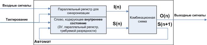
Figure 1. The general structure of digital machines
Where:
- combinational circuit (CS) - a digital logic circuit that does not contain inside the memory elements. Those. her condition is determined only by what she has at the entrance.
- The inputs of the CS are conventionally divided into two groups: I (n) —external signals (inputs of the automaton), S (n) —the internal state of the automaton at the current step. The internal state is, figuratively speaking, a kind of “mode”, which determines how the automaton will convert external signals I (n) into signals O (n). In the classical combinational circuit (there is no group of inputs S (n)), this “mode” is only one.
- The outputs of the CS are also divided into two groups O (n) - signals that go outside, which actually perform the “useful work”, S (n + 1) internal state for the next step. That is, at each step, the automaton, depending on the input signal I (n), not only calculates the desired output signal O (n), but also turns on the signal processing mode for the next step (i.e., signals I (n + 1)) and, if necessary, this mode can be the same or different. In other words, you can set the required modes for any possible cases of sequences of input signals , which makes the automata so “all-powerful”.
- For the purpose of synchronization, a memory device (memory, parallel register) is inserted which separates the word relating to the previous step from the word related to the next in the feedback circuit. The symbols n and n + 1 denote the current step, and the next step, i.e. n does not correspond to the time axis, but a sequence of steps. The steps are set by the clock signal, and the clock signal is linked to the time axis through the clock signal. The steps may not be associated with a periodic clock signal, but with the event “arrival of signal I”.
- A similar storage device for the same purpose is inserted into the channel of the input signals I
If you were not familiar with automata, for all the clarity of the explanation, the benefits of such devices are not obvious, but there is a mathematical abstraction that illustrates the essence well. The operation of the machine can be visually described using the state diagram and transitions . Below is a diagram describing the operation of the device that controls the elevator. This is a very simplified diagram that does not take into account the processes of opening / closing doors, accelerating / stopping, but it gives a visual representation of how the work of real-world objects is modeled using automata. Above the arrows is written the condition under which the transition will occur, in the oval is written
state_name / what_will_to_out_exit_ bye_automatic_in_this_state.

Figure 2. An example of a state and transition diagram
To the above, I add that the diagram shows Moore’s machine gun. The state of the outputs of such an automaton depends on the current state . The alternative is the Mile machine gun. Its output signal depends on the last perfect transition , so what_ will be_to_exit is recorded above the corresponding arrow. Despite this distinction, Mile and Mura automatons are mathematically transformed into each other. Moore’s machines are more suitable for our cognitive purposes, but in the practice of programming both abstractions are useful, so in the next part we will not ignore the Miles’s machines.
All more or less complex digital circuits are designed exactly as digital machines. Why? The indispensability of the automaton approach in the design of digital circuits is facilitated by three main advantages of the automaton approach:
- Decomposition.
- A look at the processes not as a sequence of steps , but as a collection of all possible steps .
- Maths.
Automata are a mathematical entity, their theory is widely and deeply developed, which allows using exact mathematical methods to optimize and analyze the automata obtained. From this point of view, the development of programs in a non-automatic way can be considered as the “work of the humanities”. Mathematical methods are discussed in the second part. Consider the advantages described, starting with decomposition.
Part 1. Constructive decomposition.
In the mathematical theory of automata, decomposition is the creation from an automaton, working according to a complex state and transition diagram, of several simple and clear automata that have a parallel and / or sequential connection and add up to the original automaton. This is a mathematical and, therefore, an exact procedure.
We consider practical machine building, therefore, in the first part, by decomposition we mean not a mathematical decomposition, but a splitting of an automaton in accordance with common sense. In the second part, examples of mathematical decomposition will be given.
Machines are usually divided into operating and control . The meaning is obvious from the name - the operating machine is the "hands", the manager is the "head". Moreover, the partitioning can be multi-level: the operating automaton, in turn, can be divided into executive and management parts. Those. a manipulator arm can have its own “minimal brain”, translating common commands (“take an object”) into a set of detailed commands that control each “finger”. An even more illustrative example is a processor with pipelines, registers, ALUs and FPU — operating machines, and a microprogram — a control machine.
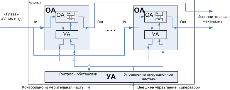
Figure 3. Decomposition of an automaton into an operating and managing director
The principle of splitting a large task into small subtasks is actually already widely used in programming practice; it is the division of a task into subprograms. However, automaton interpretation of programs, i.e. the representation of any software object in the form of an automaton, which has an operating part and a control part, allows you to get away from the mechanistic and naive (in a good sense) fragmentation of the source code and gives a set of practical considerations how to do it, which significantly improves the quality of the program at the stage design . Consider an example that will allow to talk about programmata more substantive. This example will be cross-cutting over several articles.
Formulation of the problem
_____________________________________________________________________
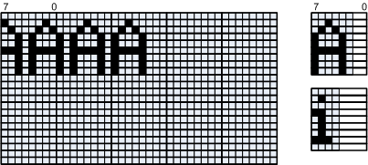
Suppose we have a b / w graphic display. Its video memory has a standard byte organization, in which each bit represents a certain point. Suppose we need to output text in different, non-monospaced fonts.
a)
b)
at)
Figure 4. Display module requirements
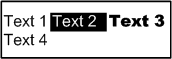
All characters in the same font height, but the font can be changed on the fly, in the process of outputting the same line. Similarly, attributes can be changed - bold, italic, underline. To control the parameters, esc-sequences are used , which include the control character '\ n', a line break, i.e. the text of one line can be displayed on several lines on the display. For example, the text:
"Text 1 \033[7m Text 2 \033[27m \033[1m Text 3 \033[21m \n Text 42" will be displayed as shown in the illustration (Fig. 4, b)
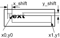
The text is displayed in the area bounded by a rectangle (Fig. 4, c) and may have an offset. The coordinates of the output area are not specified in familiarity, but in pixels, the coordinates can be negative, which means going beyond the output area. Text outside the output area is clipped.
We need to create a function that implements all this, with a prototype
void Out_text(int x0, int y0, int x1, int y1, int x_shift, int y_shift, char * Text); This is an important, basic function for all text operations: the work of the printf function, the implementation of virtual windows, crawlers, and so on.
_____________________________________________________________________
The compilation of an automaton (that is, a model of the process being implemented) is carried out from the general to the particular, from top to bottom, but the detailed elaboration of the model and its software implementation, on the contrary, occur from the bottom up. This is dictated by the fact that usually the lowest level is directly tied to the actuators, which puts us in a certain framework and limits the possibility of "maneuver", while the higher levels are more flexible in this regard, and the framework for them follows from the implementation of the underlying automatons.
The process of creating the software implementation is iterative, first the lowest level of the model (developed from top to bottom ) is implemented, then the next level is developed, the underlying level is being corrected in parallel, after which the development proceeds to a higher level, with the underlying being adjusted as necessary. Competent design requires minimal processing of the underlying levels, limited to their addition . The final realization of automata in the form of program code is carried out after the compilation of all automata, but nevertheless, the sketches of algorithms are performed in parallel with the design of automata. All the underlying calculations were performed by me, not after drawing up the program, as an illustration, but before creating the program code, as an important design stage. So, let's start developing.
As follows from the condition of the problem, the initial sequence of characters in the general case looks like: Text1 control1 Text2 control2 Text3 control3 Text4 control4 Text5 \ 0
where upN control esc-sequences, characters of translation and end of line that separate text blocks from each other. The breakdown of text into blocks is convenient in that it allows you to use the maximum number of identical settings within one block (for example, text height and the coordinates of the beginning of a line).
The development of a pair of OA-UA always begins with the development of OA. OA is built on the basis of our attempts to model all aspects of the process that our machine gun will control. In the case of the display, we have a couple of distinct aspects: splitting the text into blocks separated by control sequences and assembling graphic data in a buffer that will be reset to video memory. Consequently, the automaton will consist of two sub-devices shown in fig. five.
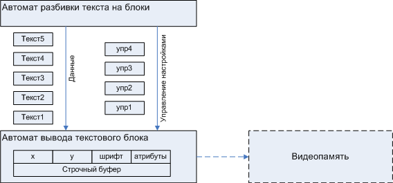
Figure 5. Initial partition
The need for an intermediate buffer assembly text block due to the fact that often work with the display is carried out over a communication channel with limited compared to the RAM bandwidth, according to the protocol type:
- first send the Write_byte command (byte coordinates on the display)
- after which it is possible to get confirmation
- and only after that you can transfer bytes.
In this case, the displays can receive a continuous stream of bytes, sequentially, line by line filling the video memory. This feature pushes us to collect a string in the buffer, throwing it in a stream of bytes in the video memory.
Each text block is characterized by x , y text block coordinates (relative to the output window), x_shift , y_shift offset relative to text block x, y coordinates, fonts and attributes, such as inverse or blinking, bold, italic, underline, and so on.
Automatic breakdown of text into blocks
The operating part of the blocking machine consists of an input stream of bytes, which is divided into blocks. To avoid unnecessary copying, text blocks are parts of the source line that are passed to the Text Block Output Machine in the form of two Text_begin and Text_end pointers.

Figure 6. Explanation of the blocking machine OA
The breakdown machine controls the settings of the Text Block Output Machine through direct access to the corresponding variables of the machine.
The automatic breakdown of text into blocks is a very simple OA, it can be said that there is no automaton, just a couple of pointers plus a set of replaceable variables, but we consider the general principle, the principle that will be useful when developing the second automaton - Automatic output of a text block
Once an OA has been developed, it is easy to make up the control automaton required for it.
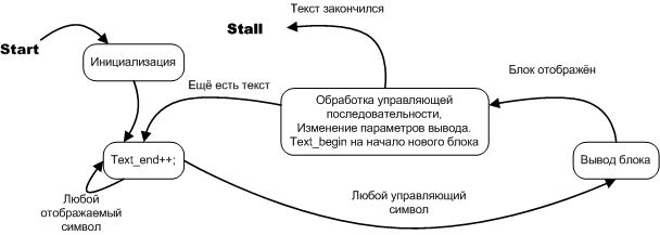
Figure 7. State diagram of the text breakdown machine
In this case, the controlling automaton is well described both in terms of the algorithmic graph-scheme and in terms of the state diagram, but since this is an automaton, we use the state diagram. The state diagram not only emphasizes the “automatism” of the task, it is useful in that it is an alternative, more convenient way of writing conventional software algorithms. If you look at the essence of the question, a state diagram is a natural form of recording a software process in a broad sense, while an algorithmic graph-diagram is an artificial construction that already contains implementation features that are most often obvious and do not require their separate recorded. Moreover, it is these very features of the implementation (when they are minor details) that sometimes disguise the main idea, pushing itself to the forefront along with the really important details. In the next part, a fine example will be given showing the difference between the algorithm given by the graph scheme and the algorithm given by the state diagram. The state diagram is elementarily converted into program code.
Text block output machine
As was shown above, control sequences can, among other things, set the output coordinates of the next text block. The coordinates of the current text block are set by variables x, y.

Figure 8. Coordinates used to display the text block
Explanation of the figure.
x_max, y_max - display size
x0, y0, x1, y1 - coordinates of the output window, Out_text function parameters
x_shift, y_shift - offset, can be positive and negative, affects the location of all text blocks.
x, y - coordinates of the output of the current text block, can be changed by esc commands. Coordinates are relative to the output window.
As noted earlier, the text is initially output to the line buffer, after which the contents of the line buffer are copied to the video memory.
The example uses a 5x7 font, but the described module supports work with characters of any size. As a result, a large string build buffer may be required, which is often an important factor for embedders. To minimize the buffer, instead of a set of parallel registers, one can be used that performs “vertical scanning”, we are talking about vertical scanning of the entire text block, i.e. displays a line one pixel high and wide across the entire text block.

Figure 9. Vertical scan when displaying text block
When correctly implemented, the speed of this variant of the algorithm is almost as good as the case with parallel registers, although it still requires overhead: 3 bytes per character, but it allows you to completely refuse the line buffer, which for the 256 pixels wide display and 24 pixels high gives savings
From these relationships, one can estimate in which case the savings will be significant. In this article we will consider the option with a full line buffer, as more simple, leaving the consideration of the "practical" option outside the scope of this article.
Since the development of a pair of OA-UA always starts with the development of OA, and the development of OA starts from the lowest level, we will compose OA for an automatic text output.
Operational automatic output of characters on the screen consists of a buffer in which a text string is collected. Since the width of the character does not equal the width of the byte, each new character will have some shift. For the implementation of the shift is used shift register. If the string buffer is a set of parallel registers corresponding to individual rows, then one shift register is required. As can be seen from the illustration, we have two end-to-end counters Current_byte and Current_shift, which, increasing from symbol to symbol, determine the amount of shift and the place where to put the shifted symbol.

Figure 10 a. Explanation of the operation of the operating unit of drawing text block.
The text collected in the string buffer is dropped into the video memory.
The control machine for the described operation machine will be

Figure 10 b. A control automaton for an operating automat of drawing a text block.
// int Current_shift, Current_byte; // u1x * Text; u1x * Text_end; tFont * Current_font; // Width - u1x * Symbol_array; int Width; // int Line_width; //////////////////////////////////////////////////////////////////////////////// //////////////////////////////////////////////////////////////////////////////// //////////////////////////////////////////////////////////////////////////////// inline void Out_text_block () { Clear_line_buffer(); // while(Text < Text_end) { Width = Current_font->Width_for(*Text); Symbol_array = Current_font->Image_for(*Text); Line_width -= Width; // , if(Line_width <= 0) break; // 10 Out_symbol(); // Current_byte, Current_shift . Current_shift += Width; Current_byte += (Current_shift >> 3); Current_shift = Current_shift & 0x7; Text ++; }// while(Text < Text_end) Finalize: Out_line_buffer_in_videomemory(); return; }// inline void Out_text_block () Note. During the actual design, this version of the function was not worked out and is presented here solely for reasons of clarity.
Our model describes the inference process in general, but does not take into account some of the features that can be illustrated in Figure 11.

Figure 11. Explanation of features of output to the line buffer and video buffer.
This drawing shows that both the line buffer and the video memory have byte organization, and the output window may not coincide with the byte boundary in the video memory. That is, output to the line buffer should be made with some initial indentation so that you can perform byte-by-byte copying.
In addition, the text can be shifted to the left outside the window border and in this case a part of the text is not displayed, and the border of the displayed part of the text can pass so that a part of the symbol is displayed and a part is not.
In other words, when developing an operational output slot machine, it should be noted that:
a) there are overlapping bytes — the bytes that contain both old data from the video memory and new data from the line buffer, so the overlapping bytes of video memory and the lines from the buffer are masked by complementary masks, after which the overlapping bytes are overlaid by or . Data of non-intersecting bytes is copied to the video memory entirely.
b) text output to the line buffer always starts with the zero byte of the line buffer, but not always from the zero position, more often it starts with some indent Current_shift initial .
c) the text, in addition to the initial shift associated with the value of the x coordinate, can be shifted beyond the left border and a part of the text beyond it is not displayed.
d) the text may protrude on the right, which requires additional masking, and, with appropriate dimensions, the same symbol may protrude on the right and on the left.
When composing an operational automaton, it is imperative to take into account all the described points, so we turn to the following abstraction. This (compilation of abstraction) is also part of the automaton approach — one should not neglect the clear visual representation of the problem, although this does not follow directly from the automaton theory. This abstraction was born after I portrayed different versions of the layout of the text.
All characters of the string are divided into categories:

Figure 12. Categories of characters displayed on the screen, depending on the location relative to the output window.
Each category implies its own processing mode:
- Characters that do not fall into the output window (1) are simply ignored.
- The first character, partially or completely trapped in the output window (2), may require an additional shift to the left compared to the type 3 in order to cut off the pixels protruding beyond the output area. The dropped bytes and bits are simply lost.

Figure 13. Explanation of the initial shear mechanism. The numbers indicate the ordinal number of pixels in the character image.
- Characters that fall completely into the output area (3), as well as characters of type (2), require shifting to the right, the value of which depends on the coordinate of the character.
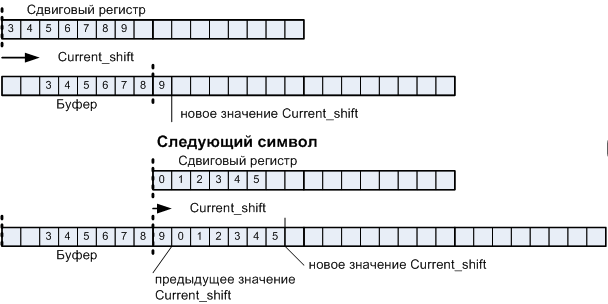
Figure 14. Explanation of the sliding shear mechanism
For the first character, the left and right shifts are performed, so it is possible to save - to actually shift the difference of the corresponding values with additional masking of the dropped pixels. The mask is obtained in a tabular way, so it practically does not require additional calculations, but this approach allows you to save up to 7 shifts per byte of the first character, which, with a character size of 16 * 24, saves up to 336 shifts.

Figure 15. Avoiding double shift
From the shift register, the data is dropped into the string buffer, which is reset before the output of the text block. Data is overlaid by or .

Figure 16. Filling the line buffer.
Bits of the line buffer that protrude beyond the output area on the right (may belong to both category 2 and category 3, are marked with an apostrophe) require additional clipping of the part of the character that does not fit on the screen on the right.

Figure 17. Handling characters 2 'and 3'.
Finalization involves copying information from the line buffer to the video memory, and if the extreme bytes intersect (see above), their information is read from the video memory and is masked by the corresponding mask for the video memory after which the trimmed byte is superimposed on the line buffer contents by or after which all the line buffer bytes is simply copied to video memory.
As was shown above, the polishing of the software implementation occurs at the last stage, however, for clarity, I will give the source code in its final form, despite the fact that the idea of eliminating double shift appeared already in the process of optimization, after the entire module was debugged, and for this we only had to slightly change the function Out_symbol. The same applies to the use of the Start_line and End_line variables, which will appear only when developing the outgoing Out_text function, but adding them only slightly affected the appearance of the Out_symbol function.
The full version of the source is located by reference in the Display.h / Display.cpp file. There is also a compiled example (Project1.exe). The project itself under Builder 6
class tShift_register Symbol_buffer; vector< tShift_register > Line_buffer; // int Start_line, End_line; int Left_shift, Current_shift, Current_byte; // Width - u1x * Symbol_array; int Width; int bytes_Width; // bytes_Width, int bytes_Width_after_shift; inline void Out_symbol () { for(int Current_line = Start_line; Current_line <= End_line; Current_line++) { Symbol_buffer.Clear(); //////////////////////// // 2 3 Out_symbol, if(Left_shift)// 2 { // 8 int Start_symbol_byte = Left_shift >> 3; // void tShift_register::Load(int Start_index_in_destination, u1x * Source, int Width); Symbol_buffer.Load(0,Symbol_array + bytes_Width * Current_line + Start_symbol_byte,\ bytes_Width - Start_symbol_byte); // .15 // void tShift_register::Shift(int Start, int End, int Amount); Symbol_buffer.Shift (0, bytes_Width_after_shift, Current_shift - (Left_shift & 7) ); Symbol_buffer[0] &= Masks_array__left_for_line_buffer[ Current_shift ]; // .16 Line_buffer[Current_line].Or(Current_byte, &Symbol_buffer[0], bytes_Width_after_shift ); } else // 3 { Symbol_buffer.Load(0,Symbol_array + bytes_Width * Current_line, bytes_Width); // .14 Symbol_buffer.Shift(0, bytes_Width_after_shift, Current_shift); // .16 Line_buffer[Current_line].Or(Current_byte, &Symbol_buffer[0], bytes_Width_after_shift ); } }// for(int Current_line = Start_line, Current_line <= End_line, Current_line++) }// inline void Out_symbol () We now turn to the control automaton. The algorithm of his work is intuitively clear from the above description of OA. As mentioned above, the state diagram is a natural and minimalistic form of writing algorithms, allowing you to show the essence without littering the drawing with minor details, so we write the algorithm for the UA as a state diagram.

Figure 18. State diagram is a good alternative to classic graph-schemes.
According to the algorithm written by this state diagram, it is easy to compose a program code consisting of classical structural structures - cycles and branching. This turns out to be simple in particular because this directed graph is, in general, not cyclic (that is, it does not contain transitions to previous states). The exception is a pair of loops (state Type 1 and Type 3), which are easily developed in cycles. However, even for those automata that are described by a more complex graph with cyclic paths of traversing nodes, it is also possible to write a structural program, although at first glance this task may seem difficult and cumbersome.I ask you to emphasize: since the state diagram deals with blocks of states that are absolutely identical from the point of view of the program process, the links between which are clearly and unambiguously defined, this allows the goto operator to go between states without disturbing the structure of the language. That is, if the goto operator is used to make transitions between states of the automaton, this in itself is a new structure, the same as cycles and branches . This structure is called the transition between states , and it enriches the programming toolkit. At the same time, it should be understood that the use of the goto operator outside of this program structure still remains non-structural.i.e. breaking the standard structures of which the program code is built. This is an important point. It may take time for people to become accustomed and stop being afraid, but I want to believe that the new structural design will take a worthy place in the programmers' toolkit.
class tShift_register Symbol_buffer; vector< tShift_register > Line_buffer; tVideomemory Videomemory; // int Start_line, End_line; // int Left_shift, Current_shift, Current_byte; // u1x * Text; u1x * Text_end; tFont * Current_font; // Out_text_block // Width - u1x * Symbol_array; int Width; int bytes_Width; // bytes_Width, int bytes_Width_after_shift; // // int Line_width; //////////////////////////////////////////////////////////////////////////////// //////////////////////////////////////////////////////////////////////////////// //////////////////////////////////////////////////////////////////////////////// inline void Out_text_block () { Clear_line_buffer(); //////////////////////////////////////// // Type_1: // while(Text < Text_end) { Width = Current_font->Width_for(*Text); // if(Left_shift >= Width) { Left_shift -= Width; Text++; } else goto Type_2; }// while(Text < Text_end) // return; //////////////////////////////////////// Type_2: // Current_byte = Current_shift >> 3; Current_shift = Current_shift & 7; Symbol_array = Current_font->Image_for(*Text); bytes_Width = (Width + 7) >> 3; bytes_Width_after_shift = (Width + Current_shift + 7) >> 3; Line_width -= (Width - Left_shift); // ? if(Line_width <= 0) { Width -= Left_shift; goto Type_4; } Out_symbol(); // Left_shift Width -= Left_shift; Left_shift = 0; // Text++; //////////////////////////////////////// Type_3: // ? while(Text < Text_end) { // Current_byte, Current_shift . Current_shift += Width; Current_byte += (Current_shift >> 3); Current_shift = Current_shift & 0x7; // Width = Current_font->Width_for(*Text); Symbol_array = Current_font->Image_for(*Text); bytes_Width = (Width + 7) >> 3; bytes_Width_after_shift = (Width + Current_shift + 7) >> 3; Line_width -= Width; // ? if(Line_width <= 0) goto Type_4; Out_symbol(); Text++; }// while(*Text < Text_end) Current_shift += Width; Current_byte += (Current_shift >> 3); Current_shift = Current_shift & 0x7; // goto Finalize; //////////////////////////////////////// // 4 2' 3' Type_4: Out_symbol(); Current_shift += (Width + Line_width); Current_byte += (Current_shift >> 3); Current_shift = Current_shift & 0x7; for(int Current_line = Start_line; Current_line <= End_line; Current_line++) { Line_buffer[Current_line][Current_byte] &= Masks_array__right_for_line_buffer[Current_shift]; } Finalize: Out_line_buffer_in_videomemory(); return; }// inline void Out_text_block () This algorithm is easy and organic, literally 1 in 1, implemented in assembly language.
Values such as Start_line, End_line, the initial values of Left_shift, Current_shift, Current_byte are set at the stage of initialization of the block output process. This happens even in the blocking machine. Consider how this happens. Let me remind you that one line can be output not by a single block, but by several, therefore, when outputting each block, we deal with the parameters shown in Fig.8 .
The coordinates of each text block (x, y) can be set individually (esc sequences, however there is a difference — the coordinates of the cursor are not specified in familiarity but in pixels). They are counted relative to the coordinates of the output window (x0, y0, x1, y1). The x_shift, y_shift offset affects the coordinates of each text block. All text blocks that fall entirely into the output window are not cut off even if a negative offset is specified. Only that which does not fall into the output window is clipped, i.e. negative bias itself is not a criterion for trimming text blocks. To implement the described behavior, the output of each text block is accompanied by the following transformations.
Calculating the parameters horizontally is illustrated in Fig. nineteen

Figure 19. Explanation of the calculation of parameters horizontally.
The value of x_shift is not shown, it is compensated by adding to x. The x_byte and Start_shift parameters are used during output to the video memory, which is carried out according to the scheme shown in Fig. 20

Figure 20. Output to video memory.
The output process is obvious, but the explanations are not redundant:
- If the left byte intersects, then the corresponding byte of the video memory is read, masked and superimposed on the leftmost byte of the line buffer (which is already masked during the output to the line buffer).
- If the rightmost byte is intersecting, the corresponding byte of video memory is read, masked, and then superimposed on the rightmost byte of the line buffer (which is masked by the padding mask).
- After that, the entire line buffer is copied to video memory, the line Start_line of the line buffer goes to line y of the buffer, and so on up to End_line and y + End_line - Start_line, respectively, as shown in Figure 20.
The parameters Start_line and End_line are determined based on the considerations shown in
rice 21.

Fig. 21. Determination of the parameters of the vertical.
// // //////////////////////////////////////////////////////////////////////////////////// if(x1 < x0) { int temp = x0; x0 = x1; x1 = temp; } if(y1 < y0) { int temp = y0; y0 = y1; y1 = temp; } if(x0 < 0) { x_shift += x0; x0 = 0; } if(y0 < 0) { y_shift += y0; y0 = 0; } if(x1 > x_max) { x1 = x_max; } if(y1 > y_max) { y1 = y_max; } // inline bool Init_text_block() { // //////////////////////////////////////////////////////////////////////////////////// x += ( x0 + x_shift); y += ( y0 + y_shift); // //////////////////////////////////////////////////////////////////////////////////// if (x < x0) { Left_shift = x - x0; x = x0; } else { Left_shift = 0; } if(x >= x1) return false; x_byte = x >> 3; Start_shift = Current_shift = x & 7; Current_byte = 0; Line_width = x1-x; // //////////////////////////////////////////////////////////////////////////////////// if (y < y0) { Start_line = y0 - y; y = y0; } else Start_line = 0; if(Start_line >= Current_font->Height()) return false; if( (Current_font->Height() - Start_line) < ( y1 - y) ) End_line = Current_font->Height() - 1; else End_line = Start_line + (y1 - y) - 1; return true; } It should be added that only the content of the text block is actually displayed, and not the entire output window bounded by the coordinates x0, y0, x1, y1. If necessary, you can pre-clear the entire window separately.
Automatic breakdown of the source text into blocks.
The state and transition diagram has already been shown in Figure 7.
/////////////////////////////////////////////////////////////////////////////////// /////////////////////////////////////////////////////////////////////////////////// /////////////////////////////////////////////////////////////////////////////////// /////////////////////////////////////////////////////////////////////////////////// /////////////////////////////////////////////////////////////////////////////////// /////////////////////////////////////////////////////////////////////////////////// // void Out_text_block (); inline void Control_processing (); void Out_text (int arg_x0, int arg_y0, int arg_x1, int arg_y1, int arg_x_shift, int arg_y_shift, unsigned char * argText) { // // ... while(*Text_end) { ////////////////////////////////////// state__Inside_text_block: while(1) { switch(*Text_end) { // case '\0': case '\n': goto state__Out_text_block; } Text_end++; } ////////////////////////////////////// state__Out_text_block: if( (Text_begin != Text_end) && Init_text_block()) Out_text_block(); Text_begin = Text_end; ////////////////////////////////////// state__Control_processing: if(*Text_end == 0) return; // Control_processing(); }//while(*Text_end) }//void Out_text (int arg_x0, int arg_y0, So in general terms the solution to the problem. Under the link you can see the source code and the working version of the program (Project1.exe file). The only question that remains is not solved - the structure of the function Control_processing, which parses esc-sequences and executes commands. It is based on another type of automata, which differs markedly from those considered above, but which are at the same time classic software automata - symbolic automata. We consider the implementation of such machines in one of the following parts.
It is impossible to describe such a versatile topic as Automata programming in one article. This article is an introductory, it is a sketch of the first cycle of articles, in which I want to acquaint the reader with the “automaton programming culture”. The central element of the automaton approach is the automaton method of describing the processes occurring in time - with the help of a state diagram and transitions. This is an alternative form of writing algorithms. The next article will be devoted to a state diagram and transitions
Source: https://habr.com/ru/post/331556/
All Articles