An example of the synthesis of asynchronous SI circuits in a two-way element base: C-element
In a previous publication, I presented a method for synthesizing asynchronous circuits in the minimum element base. This method does not require the calculation of logical functions, but is the correction of the original behavior by adding additional signals. Let me show you by the example of the C-element how it works.
The initial behavior is as follows:
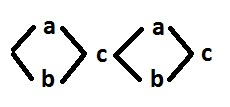
Signals a, b - input, c - output. The signs of the events are not indicated, because for the synthesis it is superfluous information and to optimize them it is better to arrange them at the end. The purpose of the synthesis is to add additional signals so that each non-input signal f can be entered into the following patterns:

In general, there are several more such templates, but in this case only these are sufficient.
Let's look at the original behavior and determine the existing problems. First, it is the presence of two synchronization of parallel branches. Secondly, the presence of input signals. There are no two consecutive switching of input signals in the initial behavior, therefore input signals are not a problem. But at the decomposition stage, the problems associated with the input signals may still appear.
')
As a result, we need to provide two synchronization. One signal can provide only one synchronization (signal f in the second pattern). The c signal cannot be used for synchronization; it does not fit into the pattern. So, synchronization requires at least 2 additional signals. And in this case, two signals are enough:

The signals f, g fit into the pattern, i.e. already have a two-way implementation. We declare them pseudo. Signals a, b now cause only pseudo-input events. Therefore, they can be removed from further consideration. As a result, we get the behavior:

The signals f, g are pseudo input.
There are no violations of CSC. Therefore, it would seem, it is possible to proceed to decomposition. But, since the signal c requires representation in the form of a trigger (for decomposition), and at the same time, the signal c causes only pseudo-input events, the switching of the dual signal would have to be set in parallel with the subsequent synchronization. And this is too complicated decision. In this case, it is easier to force the signal c into the template by adding 1 or 2 additional signals. Such addition, if not to insert two switchings of one signal in a row, does not lead to violations of the CSC, and does not prevent the decomposition of both old and new signals.
In our case, we have to add 2 signals h and i, and the only possible way:

The signals f, g are pseudo input.
Now you can go to the decomposition. Representation in the form of a trigger requires only signal i, so we add a dual signal j:

As a result, all signals c, h, i, j fit into the pattern, and the decomposition itself does not need to be done.
Now we will restore the signals a and b, previously removed from consideration. In this way, we obtain a corrected initial behavior in which all non-input signals fit into the pattern.

It remains only to arrange the signs so as to minimize the number of additional inverters.

And now we introduce the inverters k and n to eliminate the inconsistencies at the inputs of the elements g and i.

As a result, the correction did not distort the original behavior. Logical functions look like this:
C-Element Scheme:

For comparison, a curious implementation on three-input elements. The behavior looks like this.

Logical functions:
And the scheme itself.

The initial behavior is as follows:
Signals a, b - input, c - output. The signs of the events are not indicated, because for the synthesis it is superfluous information and to optimize them it is better to arrange them at the end. The purpose of the synthesis is to add additional signals so that each non-input signal f can be entered into the following patterns:
In general, there are several more such templates, but in this case only these are sufficient.
Let's look at the original behavior and determine the existing problems. First, it is the presence of two synchronization of parallel branches. Secondly, the presence of input signals. There are no two consecutive switching of input signals in the initial behavior, therefore input signals are not a problem. But at the decomposition stage, the problems associated with the input signals may still appear.
')
As a result, we need to provide two synchronization. One signal can provide only one synchronization (signal f in the second pattern). The c signal cannot be used for synchronization; it does not fit into the pattern. So, synchronization requires at least 2 additional signals. And in this case, two signals are enough:
The signals f, g fit into the pattern, i.e. already have a two-way implementation. We declare them pseudo. Signals a, b now cause only pseudo-input events. Therefore, they can be removed from further consideration. As a result, we get the behavior:
The signals f, g are pseudo input.
There are no violations of CSC. Therefore, it would seem, it is possible to proceed to decomposition. But, since the signal c requires representation in the form of a trigger (for decomposition), and at the same time, the signal c causes only pseudo-input events, the switching of the dual signal would have to be set in parallel with the subsequent synchronization. And this is too complicated decision. In this case, it is easier to force the signal c into the template by adding 1 or 2 additional signals. Such addition, if not to insert two switchings of one signal in a row, does not lead to violations of the CSC, and does not prevent the decomposition of both old and new signals.
In our case, we have to add 2 signals h and i, and the only possible way:
The signals f, g are pseudo input.
Now you can go to the decomposition. Representation in the form of a trigger requires only signal i, so we add a dual signal j:
As a result, all signals c, h, i, j fit into the pattern, and the decomposition itself does not need to be done.
Now we will restore the signals a and b, previously removed from consideration. In this way, we obtain a corrected initial behavior in which all non-input signals fit into the pattern.
It remains only to arrange the signs so as to minimize the number of additional inverters.
And now we introduce the inverters k and n to eliminate the inconsistencies at the inputs of the elements g and i.
As a result, the correction did not distort the original behavior. Logical functions look like this:
C-Element Scheme:
For comparison, a curious implementation on three-input elements. The behavior looks like this.
Logical functions:
And the scheme itself.
Source: https://habr.com/ru/post/331314/
All Articles