A fistful of relays. Part 4. System commands or what can fit in 8 machine instructions?
Finally, you can run a program longer than one instruction in my computer on electromagnetic relays. Now it has a ROM for 8 commands, a processor with an ALU and 8 eight-bit registers (one of which is a PC).
In total, the processor supports 5 groups of instructions: Arithmetic Logical Operations (ALU), Number Load to the Register (MOVI), Inter-register Transfer (MOV), Work Stop (HALT), Memory Operation (LDST). But there are nuances ...
In addition to these 5 groups, the code reserved for the NOP operation in the description , although it is not decoded by the processor in any way. In reality, all unused combinations will work as NOPs.
Forwarding commands
What can be done with such a set of commands, if there are not even transitions? Since the PC is included in the register file along with the other registers (A, B, C, D, M, S, L), all operations with it are done the same way as with other registers. Then loading an integer number in the PC is going to the address.
')
The two MOVI instruction fields are a register and an 8-bit immediate operand. All the commands I have are 16-bit to simplify loading them from memory, decoding, and programming in native code. The MOVI instruction code looks like this:
1cccLddd iiiiiiiiThe i field is the value written to the register, the d field is which register changes, 1 is for this bit, we understand that it is the MOVI instruction that we have before us.
It remains 4 bits. 3 of them (c) are given under the conditions under which the instruction is executed. A total of 7 combinations are involved: the transition is always on the zero flag on / off, the transfer flag, the flag flag. The eighth combination is not used.
The last remaining bit (L) allows you to implement the subroutine call command. If this bit is set, the instruction writes the address of the next instruction to the register L. It turns out as in any ARM and MIPS - the procedure call is just a transition with the entry of the address of the next instruction in a special register. To return from the procedure, you need to copy this value back to the PC. Therefore, we do not need any separate RET command.
But then you will need the instruction to copy one register to another - MOV. In fact, it could be implemented using the ALU (for example, as ADD D, S, 0 or OR D, S, S), but I did not immediately think about it. Plus, the resulting solution also exists - the relays in the ALU module wear less, since it is used only for arithmetic and logical operations, and the flags do not deteriorate during normal shipments.
The MOV team itself is unremarkable, except for one side effect associated with the design of the computer circuit. The algorithm of its operation is as follows: reset the receiver register, connect the source register and the receiver to the same bus, so that the receiver also switches on the relay where they are already included in the source. Because of this, forwarding commands to the register from themselves will not work as the NOP, but as a register reset.
ALU
The most interesting thing is hidden in this category - all arithmetic and logical operations, but here the ALU is directly involved in determining the type of operation. At the entrance it has an operation code, 2 registers or a register + immediate value, at the output - one register. In order not to work out as with MOV, the ALU inside contains a shadow register into which the result of the calculation is written. Therefore, the operands of arithmetic logic commands can be any registers in any combination.
The general format of the command is:
01bbbddd ixxxryyy - ADD, ADC, SUB, SBC, AND, OR, XOR
01111ddd -xxxruu0 - NOT, SHR, ROR, RCR
Here d is the code of the output register, x, y are the codes of the input registers, b is the type of the binary operation, u is the type of the unary operation. If the i flag is set, then the three bits of yyy are used as the immediate second operand of the command. So it is more convenient to add / subtract small constants.
Shift operations work like the Z80, not like the i386 - they shift only one bit. There is no left shift, because you can do with addition for everything except cyclic shift. Well, the cyclic shift to the left is done for two instructions:
ADD A, A, A
ADC A, A, 0
The ALU stores the three flags of the last operation - the carry, zero, sign. And they change only when the ALU performs the next command and does not spoil the rest of the instructions. If desired, the flags can be returned even from the function.
It is not always convenient to overwrite the register to get the flag values. To make a command like CMP or TST like in i386, you need to reset the r bit in the ALU instruction code. Then the result of the calculation will remain only in the shadow register (so that the flags can be counted), and the usual registers will not change.
Fire catch and
HALT - command to stop the computer. The work of the clock generator stops, everything stops. You can continue to work with the next command by pressing the "start" button.
Work with memory
There is also a pair of instructions for working with memory (read / write at the address in the register and at the immediate address). But since from memory now there are only 8 words of ROM, there is not much sense from these instructions.
ROM
ROM on the idea takes 64 addresses of the entire eight-bit bus. At each address, 16 bits can be read when sampling a command or 8 low bits of this command when sampling data.
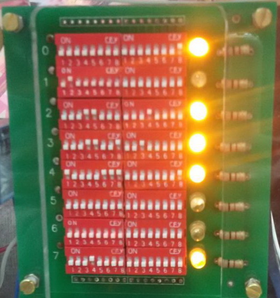
The ROM cell consists of two DIP switches. So you can easily type the program, as well as check what is “recorded” in the cells. Opposite each instruction there is a LED to monitor the progress of the program.

The problem “unexpectedly” arose when I forgot to consider that the current can flow through the key in both directions. Therefore, when selecting one cell, several others could connect to the bus at once:
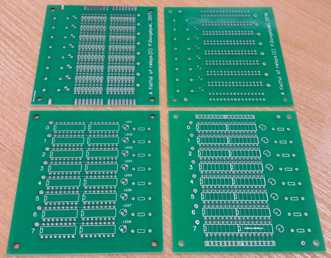
I had to order a new set of boards in which I had already provided a place for diodes. True, soldering now takes a lot longer because 128 SMD diodes must be soldered for every 8 ROM cells.
What can fit in 8 instructions?
So far I have written only a program for calculating Fibonacci numbers:
1000 0001 0000 0001 00: movi B, 1
0100 1010 0001 1000 01: add C, B, A
0001 1000 0001 0000 02: mov A, B
0001 1001 0010 0000 03: mov B, C
1000 0111 0000 0001 04: jmp 01
It took only 5 words from the available 8, which means you can come up with a program and more difficult, but there are no interesting ideas yet.
» Project page on github
» Detailed description of the command system
» The first part of the description
» The second part of the description
» The third part of the description
Source: https://habr.com/ru/post/331208/
All Articles