Petrify Asynchronous Circuit Synthesis System: Problems and Solutions
To say that Petrify solves the tasks assigned to her can only be a stretch. Rather, it can do something for small tasks (where the number of signals barely exceeds 20), the problem of state explosion has not been resolved. But even for such tasks, a satisfactory result is not guaranteed. Decomposition does not always give acceptable results.
What is the reason for these failures? I would name 3 main ones:
1. STG passion. Yes, this is a beautiful, funny model, very interesting to play with markers, etc. But, think, the process of switching signals of a circuit is the same process as the execution of a program. We use to describe the petri net program? Why then are they needed when describing the processes occurring in the scheme? As a result, Petrify developers spent the lion's share of their efforts on studying the properties of Petri nets. But the actual problem of synthesis schemes have not been solved.
')
2. The emphasis on "computation". By this I mean the conviction that in order to synthesize circuits, it is necessary to calculate logical functions. As a result, instead of solving the problems of synthesis, only the possibilities of reducing such calculations were investigated.
3. Inability to understand the causes of problems. But more on that below.
Is there anything good in Petrify? Yes there is! This is a DECOMPOSITION. In fact, it is a natural, fundamental and beautiful method. It is only important to understand the reasons why it is usually impossible to decompose to the minimum two-entry elements without violating the speed-dependent. And the reason for this - multiple signals. By this I mean signals that switch more than 2 times per cycle, or signals that switch in two or more alternative branches. The authors of Petrify did not establish this fact, which is evidenced by the “greedy” algorithm for adding additional signals. In this case, the number of additional signals decreases due to an increase in the number of switchings of such signals. Yes, it reduces the amount of computation (which, as I will show below, is not needed at all), but it creates additional problems for decomposition.
I will show an example of what I mean. Consider the behavior with the following restrictions:
1. no choice;
2. no concurrency;
3. no input signals;
4. behavior is alternated, followed by "+" followed by "-", followed by "-" - "+";
5. all signals are switched strictly 2 times.
Elimination of CSC contradictions, even with the preservation of the above limitations, should not cause problems for anyone. Now each signal can be represented as a trigger:
It was:
has become:
After that, the equation in general form for each signal looks like this:
The signal behavior of this equation looks like this:
To calculate such an equation is not necessary. It is necessary to find on the graph a chain of pickups a, b, c, d (counterclockwise) from x-, jumping over x +. CSC property provides this.
And now we make the decomposition of this equation:
The behavior will look like this:

As can be seen in this way, a speed independent scheme can be synthesized on two-input elements. It seems that the presentation of each signal in the form of a trigger looks cumbersome, but not every signal needs it. The violations of the alternation that occur in this case are solved very easily, as I will show below.
So, we can synthesize a scheme on two-input elements for any behavior that satisfies the 5 above listed restrictions. We begin these restrictions gradually remove.
We remove the restriction 4 - the requirement of the character alternation. In the resulting summary, all two-entry elements have two kinds of behavior:

Cancellation of constraint 4 can create only one problem: mismatch of the direction of switching between signals a and b. This is corrected by the introduction of an inverter (signal c). Again without disrupting speed-independe.
In this regard, the signs can be placed at the very end of the circuit synthesis process (in order to minimize the number of additional inverters).
Remove the restriction 3, enter the input signals. Since switching an additional signal makes the input switching a bad practice, we will forbid it. This can cause problems, a symptom of which is the situation when switching the input signal causes the input signal to switch. In total there are 3 classes of problem behaviors.
1 class. In simplified form, this input is switched twice in a row:
In this case, you have to insert additional events before the input. Otherwise, the scheme can not be built at all. This is done in the most gentle way. Corrected as follows:
Wherein:
Signals a, b, c are declared pseudo input, i.e. a ban on the insertion of additional events in front of them. Then you can work with the behavior as described above, and the signal n can be removed from consideration altogether.
Class 2 - the choice, depending on the order of switching two input signals:

Here I am running ahead, because the restriction on the use of choice has not yet been removed. The meaning of the correction is to obtain a behavior with a simple choice, depending on which of the two pseudo-input signals is switched (h or g).
Signals e, j, i, h, f, k, g are declared pseudo input. Signals a, b can be removed from consideration. A more complex correction in the upper branch is due to the switching order of a- and b-. If you swap them in the upper branch, the solution will be the same as in the lower branch.
Grade 3 - the choice of level. The choice is made at the time of switching the input signal a + depending on the value of the input signal b, which has settled at this point.
The purpose of the correction is the same as in the previous case.
Signals g, h, f, j are declared pseudo input. Signals a, b, g can no longer be considered. The selection is now determined by the h + and j + events. As you can see here, there is not even a speed-dependent violation.
Now we remove the restriction 5, we introduce multiple signals.
To neutralize the multiple signal x, we introduce additional signals.
Signals x, b, g are declared pseudo input. Signal x can no longer be considered.
Cancel constraint 2, we introduce parallelism. The following problems are associated with concurrency.
1. It is necessary to provide synchronization of parallel branches.
Signals f, g are declared pseudo input.
2. Event a + cannot be the cause of event b- if events a- and b + are parallel.
In addition to the above problems, concurrency does not prevent decomposition.
Finally, cancel restriction 1, we introduce a choice.
For convenience, we will consider behavior without parallelism. And the choice is made depending on the switching of one of the two input signals. Behavior will be represented in the form of a directed graph, where vertices are selection points, arcs are consecutive switching of signals. Each peak has exactly two output arcs.
The method of synthesis consists in the sequential fragmentation of the initial behavior with a choice to obtain several separate behaviors without a choice.
Define the concept: the set of reachable arcs from arc N. These are all arcs through which all possible paths from arc N are passed. Moreover, the selection point from which arc N comes is the last one for each path.
For example: for arc 4, the set of reachable arcs is {4, 5, 6, 1, 2}. For arc 3 - {3, 1, 2}. The synthesis algorithm is as follows. For each selection point, for both its output arcs, we search for the set of reachable arcs.
1. If there is a choice point for which the sets of reachable arcs do not intersect. At this point, the behavior can be divided into separate parts. To do this, we isolate the signals that are switched in both parts.
Signals x, c, d are now pseudo input. Signal x is not considered further. Now there are no common signals in both parts. The interaction between the parts is carried out using input and pseudo-input signals. Each such part can be considered as a separate behavior. At the same time, the number of selection points in comparison with the initial behavior decreased by at least 1.
2. If for all selection points the sets of reachable arcs intersect, but there is a selection point where these sets do not coincide. At this point, the behavior can be divided into two parts, but in a more complicated way.

The separation takes place at the selection point with output arcs 4 and 3. Otherwise, all the same: isolation of common signals and separation into two separate behaviors with fewer selection points.
3. If for all points of choice the sets of reachable arcs coincide. We take any arc and isolate all signals that are switched in it an odd number of times.

The signals x, y, c, d are now pseudo-input. After that we isolate multiple signals. In the selected arc, there are only signals that switch only in this arc (two times). Such an arc can be considered as a full cyclical behavior. This arc is removed from the original behavior, so that the number of selection points is reduced by 1.
Thus, the behavior with a choice is gradually broken up into behavior without choice.
The method described above is not artificial, invented. Although the synthesis of circuits on two-input elements seems extreme, in fact it is simple in the sense that it limits the space of possible solutions to the limit. For example, isolation of multiple signals is not needed for decomposition, and not for crushing behaviors with a choice. Insulation is needed by itself. Without it, it is impossible to embed multiple signals into a two-input circuit. And if you have to make isolation, then it is absolutely pointless to refuse decomposition and the fragmentation of behaviors with a choice.
All the problems described are inherent in the synthesis in an arbitrary elemental base. Only the solution of these problems is usually random, not explicit. And as a result of this, they are redundant. For example, I compared my solutions with Petrify benchmarks. My solutions are 1.5 times smaller. And this is despite the fact that Petrify allows itself such liberties as the use of non-standard elements (C-element), the use of elements with two-level logic, a much smaller restriction on the number of inputs of the element, the restriction on delays when using input inverters.
What is the reason for these failures? I would name 3 main ones:
1. STG passion. Yes, this is a beautiful, funny model, very interesting to play with markers, etc. But, think, the process of switching signals of a circuit is the same process as the execution of a program. We use to describe the petri net program? Why then are they needed when describing the processes occurring in the scheme? As a result, Petrify developers spent the lion's share of their efforts on studying the properties of Petri nets. But the actual problem of synthesis schemes have not been solved.
')
2. The emphasis on "computation". By this I mean the conviction that in order to synthesize circuits, it is necessary to calculate logical functions. As a result, instead of solving the problems of synthesis, only the possibilities of reducing such calculations were investigated.
3. Inability to understand the causes of problems. But more on that below.
Is there anything good in Petrify? Yes there is! This is a DECOMPOSITION. In fact, it is a natural, fundamental and beautiful method. It is only important to understand the reasons why it is usually impossible to decompose to the minimum two-entry elements without violating the speed-dependent. And the reason for this - multiple signals. By this I mean signals that switch more than 2 times per cycle, or signals that switch in two or more alternative branches. The authors of Petrify did not establish this fact, which is evidenced by the “greedy” algorithm for adding additional signals. In this case, the number of additional signals decreases due to an increase in the number of switchings of such signals. Yes, it reduces the amount of computation (which, as I will show below, is not needed at all), but it creates additional problems for decomposition.
I will show an example of what I mean. Consider the behavior with the following restrictions:
1. no choice;
2. no concurrency;
3. no input signals;
4. behavior is alternated, followed by "+" followed by "-", followed by "-" - "+";
5. all signals are switched strictly 2 times.
Elimination of CSC contradictions, even with the preservation of the above limitations, should not cause problems for anyone. Now each signal can be represented as a trigger:
It was:
has become:
After that, the equation in general form for each signal looks like this:
The signal behavior of this equation looks like this:
To calculate such an equation is not necessary. It is necessary to find on the graph a chain of pickups a, b, c, d (counterclockwise) from x-, jumping over x +. CSC property provides this.
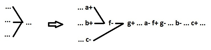
And now we make the decomposition of this equation:
The behavior will look like this:
As can be seen in this way, a speed independent scheme can be synthesized on two-input elements. It seems that the presentation of each signal in the form of a trigger looks cumbersome, but not every signal needs it. The violations of the alternation that occur in this case are solved very easily, as I will show below.
So, we can synthesize a scheme on two-input elements for any behavior that satisfies the 5 above listed restrictions. We begin these restrictions gradually remove.
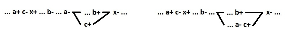
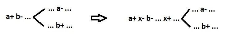
We remove the restriction 4 - the requirement of the character alternation. In the resulting summary, all two-entry elements have two kinds of behavior:
Cancellation of constraint 4 can create only one problem: mismatch of the direction of switching between signals a and b. This is corrected by the introduction of an inverter (signal c). Again without disrupting speed-independe.
In this regard, the signs can be placed at the very end of the circuit synthesis process (in order to minimize the number of additional inverters).
Remove the restriction 3, enter the input signals. Since switching an additional signal makes the input switching a bad practice, we will forbid it. This can cause problems, a symptom of which is the situation when switching the input signal causes the input signal to switch. In total there are 3 classes of problem behaviors.
1 class. In simplified form, this input is switched twice in a row:
In this case, you have to insert additional events before the input. Otherwise, the scheme can not be built at all. This is done in the most gentle way. Corrected as follows:
Wherein:
Signals a, b, c are declared pseudo input, i.e. a ban on the insertion of additional events in front of them. Then you can work with the behavior as described above, and the signal n can be removed from consideration altogether.
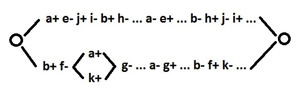
Class 2 - the choice, depending on the order of switching two input signals:
Here I am running ahead, because the restriction on the use of choice has not yet been removed. The meaning of the correction is to obtain a behavior with a simple choice, depending on which of the two pseudo-input signals is switched (h or g).
Signals e, j, i, h, f, k, g are declared pseudo input. Signals a, b can be removed from consideration. A more complex correction in the upper branch is due to the switching order of a- and b-. If you swap them in the upper branch, the solution will be the same as in the lower branch.
Grade 3 - the choice of level. The choice is made at the time of switching the input signal a + depending on the value of the input signal b, which has settled at this point.
The purpose of the correction is the same as in the previous case.
Signals g, h, f, j are declared pseudo input. Signals a, b, g can no longer be considered. The selection is now determined by the h + and j + events. As you can see here, there is not even a speed-dependent violation.
Now we remove the restriction 5, we introduce multiple signals.
To neutralize the multiple signal x, we introduce additional signals.
Signals x, b, g are declared pseudo input. Signal x can no longer be considered.
Cancel constraint 2, we introduce parallelism. The following problems are associated with concurrency.
1. It is necessary to provide synchronization of parallel branches.
Signals f, g are declared pseudo input.
2. Event a + cannot be the cause of event b- if events a- and b + are parallel.
In addition to the above problems, concurrency does not prevent decomposition.
Finally, cancel restriction 1, we introduce a choice.
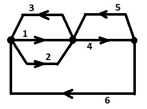
For convenience, we will consider behavior without parallelism. And the choice is made depending on the switching of one of the two input signals. Behavior will be represented in the form of a directed graph, where vertices are selection points, arcs are consecutive switching of signals. Each peak has exactly two output arcs.
The method of synthesis consists in the sequential fragmentation of the initial behavior with a choice to obtain several separate behaviors without a choice.
Define the concept: the set of reachable arcs from arc N. These are all arcs through which all possible paths from arc N are passed. Moreover, the selection point from which arc N comes is the last one for each path.
For example: for arc 4, the set of reachable arcs is {4, 5, 6, 1, 2}. For arc 3 - {3, 1, 2}. The synthesis algorithm is as follows. For each selection point, for both its output arcs, we search for the set of reachable arcs.
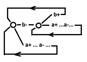
1. If there is a choice point for which the sets of reachable arcs do not intersect. At this point, the behavior can be divided into separate parts. To do this, we isolate the signals that are switched in both parts.
Signals x, c, d are now pseudo input. Signal x is not considered further. Now there are no common signals in both parts. The interaction between the parts is carried out using input and pseudo-input signals. Each such part can be considered as a separate behavior. At the same time, the number of selection points in comparison with the initial behavior decreased by at least 1.
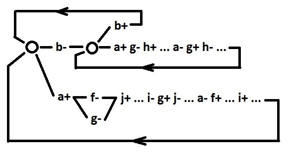
2. If for all selection points the sets of reachable arcs intersect, but there is a selection point where these sets do not coincide. At this point, the behavior can be divided into two parts, but in a more complicated way.
The separation takes place at the selection point with output arcs 4 and 3. Otherwise, all the same: isolation of common signals and separation into two separate behaviors with fewer selection points.
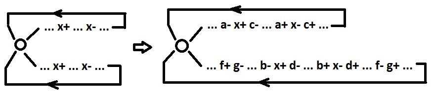
3. If for all points of choice the sets of reachable arcs coincide. We take any arc and isolate all signals that are switched in it an odd number of times.
The signals x, y, c, d are now pseudo-input. After that we isolate multiple signals. In the selected arc, there are only signals that switch only in this arc (two times). Such an arc can be considered as a full cyclical behavior. This arc is removed from the original behavior, so that the number of selection points is reduced by 1.
Thus, the behavior with a choice is gradually broken up into behavior without choice.
The method described above is not artificial, invented. Although the synthesis of circuits on two-input elements seems extreme, in fact it is simple in the sense that it limits the space of possible solutions to the limit. For example, isolation of multiple signals is not needed for decomposition, and not for crushing behaviors with a choice. Insulation is needed by itself. Without it, it is impossible to embed multiple signals into a two-input circuit. And if you have to make isolation, then it is absolutely pointless to refuse decomposition and the fragmentation of behaviors with a choice.
All the problems described are inherent in the synthesis in an arbitrary elemental base. Only the solution of these problems is usually random, not explicit. And as a result of this, they are redundant. For example, I compared my solutions with Petrify benchmarks. My solutions are 1.5 times smaller. And this is despite the fact that Petrify allows itself such liberties as the use of non-standard elements (C-element), the use of elements with two-level logic, a much smaller restriction on the number of inputs of the element, the restriction on delays when using input inverters.
Source: https://habr.com/ru/post/331142/
All Articles