Our recipe for a fail-safe Linux router

In high-load projects there are always increased requirements for redundancy and reliability. One of the most important links in the infrastructure is the router, because the availability of the network as a whole depends on its stability. It is on such nodes that we use one of the schemes for implementing a GNU / Linux fault-tolerant virtual router using iproute2, NetGWM, keepalived, ISC DHCPD, PowerDNS. How we customize all this, read in this article.
Components
In the ideal scheme of a fault-tolerant router, we reserve all the elements that can lead to network unavailability, that is:
- channels of connection,
- switches,
- routers.
In general, the scheme (at the L2 level) looks like this:
')
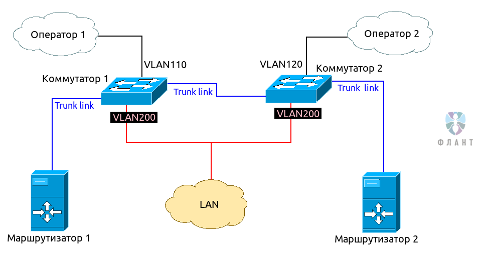
As can be seen from the diagram, we need 2 switches with support for 802.1Q VLAN. Operator 1 switches to Switch 1 and is assigned a separate VLAN (for example, 110). Operator 2 is switched to Switch 2 in another VLAN (for example, 120). Separate VLAN (in our case - 200), is allocated for the local network. A trunk is established between the switches, and the trunk links both routers, which will be the “heart” of our virtual router ( router-on-a-stick scheme).
Such a layout allows the network to remain operational when any component fails: a router, a switch or an operator.
Stack of basic components that we use in the work of routers:
- Ubuntu Linux;
- NetGWM is the primary gateway prioritization utility in the solution. This is our Open Source-development, about which we are preparing a separate article (for now, I propose to become familiar with the basic documentation ) [ Updated 08.08.2017 : the article was published as “ Setting up the main and two backup operators on a Linux-router with NetGWM ”] ;
- iproute2 - to create multiple routing tables;
- keepalived - for implementing the VRRP protocol in Linux;
- ISC DHCPD - as a horizontally scalable DHCP server;
- PowerDNS - as a DNS server for the local network.
Routers are configured in approximately the same way, except for the configuration of IP addresses and keepalived.
Interface Configuration
We configure VLAN. The configuration of
/etc/network/interfaces will look something like this: auto lo iface lo inet loopback post-up bash /etc/network/iprules.sh post-up ip route add blackhole 192.168.0.0/16 dns-nameservers 127.0.0.1 dns-search dz # lan, wan: trunk dot1q auto eth0 iface eth0 inet manual # lan auto vlan200 iface vlan200 inet static vlan_raw_device eth0 address 192.168.1.2 netmask 255.255.255.0 # Operator1 auto vlan110 iface vlan110 inet static vlan_raw_device eth0 address 1.1.1.2 netmask 255.255.255.252 post-up ip route add default via 1.1.1.1 table oper1 post-up sysctl net.ipv4.conf.$IFACE.rp_filter=0 post-down ip route flush table oper1 # Operator2 auto vlan120 iface vlan120 inet static vlan_raw_device eth0 address 2.2.2.2 netmask 255.255.255.252 post-up ip route add default via 2.2.2.1 table oper2 post-up sysctl net.ipv4.conf.$IFACE.rp_filter=0 post-down ip route flush table oper2 Highlights:
- set up a blackhole - a good practice for local packets not to fly along the default route towards the provider;
net.ipv4.conf.$IFACE.rp_filter=0- needed for multi-wan to work correctly;- for each provider we set up a separate routing table with a single default route.
Configure packet marking to route to certain tables — add rules to iptables:
iptables -t mangle -A PREROUTING -i vlan110 -m conntrack --ctstate NEW,RELATED -j CONNMARK --set-xmark 0x1/0x3 iptables -t mangle -A PREROUTING -i vlan120 -m conntrack --ctstate NEW,RELATED -j CONNMARK --set-xmark 0x2/0x3 iptables -t mangle -A PREROUTING -j CONNMARK --restore-mark --nfmask 0xffffffff --ctmask 0xffffffff iptables -t mangle -A OUTPUT -o vlan110 -m conntrack --ctstate NEW,RELATED -j CONNMARK --set-xmark 0x1/0x3 iptables -t mangle -A OUTPUT -o vlan120 -m conntrack --ctstate NEW,RELATED -j CONNMARK --set-xmark 0x2/0x3 iptables -t mangle -A OUTPUT -j CONNMARK --restore-mark --nfmask 0xffffffff --ctmask 0xffffffff iptables -t mangle -A POSTROUTING -o vlan110 -m conntrack --ctstate NEW,RELATED -j CONNMARK --set-xmark 0x1/0x3 iptables -t mangle -A POSTROUTING -o vlan120 -m conntrack --ctstate NEW,RELATED -j CONNMARK --set-xmark 0x2/0x3 And we will configure the routing rules for the marked packets - we do this by calling the
iprules.sh script when running ifup lo (see above in /etc/network/interfaces ). Inside the script: #!/bin/bash /sbin/ip rule flush #operator 1 /sbin/ip rule add priority 8001 iif vlan110 lookup main /sbin/ip rule add priority 10001 fwmark 0x1/0x3 lookup oper1 /sbin/ip rule add from 1.1.1.2 lookup oper1 #operator 2 /sbin/ip rule add priority 8002 iif vlan120 lookup main /sbin/ip rule add priority 10002 fwmark 0x2/0x3 lookup operator2 /sbin/ip rule add from 2.2.2.2 lookup operator2 These routing tables must be declared in
/etc/iproute2/rt_tables : # reserved values 255 local 254 main 253 default 0 unspec # local 110 oper1 120 oper2 Main Gateway Balancer
Configure NetGWM, a utility for prioritizing the default gateway. It will set the default route, choosing operators according to two rules: a) the priority we set, b) the status of the operator (live or not).
To install NetGWM, you can use the source code on GitHub or our repository for Ubuntu. The second way with Ubuntu 14.04 LTS is as follows:
# $ sudo wget https://apt.flant.ru/apt/flant.trusty.common.list -O /etc/apt/sources.list.d/flant.common.list # $ wget https://apt.flant.ru/apt/archive.key -O- | sudo apt-key add - # HTTPS- — , $ sudo apt-get install apt-transport-https # netgwm $ sudo apt-get update && sudo apt-get install netgwm We indicate in the
/etc/netgwm/netgwm.yml config that we have 2 operators, default routes for each of them, prioritization and settings for accessibility control: # # () gateways: oper1: {ip: 1.1.1.1, priority: 1} oper2: {ip: 2.2.2.1, priority: 2} # , «» # online, offline, # -. ( ), # netgwm , min_uptime: 900 # , netgwm # check_sites: - 192.5.5.241 - 198.41.0.4 Note the names
oper1 and oper2 are the names of the routing tables from /etc/iproute2/ip_tables . Restartn netgwm service to start managing the default gateway for the system: $ sudo service netgwm restart Keepalived setting
Keepalived - implementation of the VRRP protocol for Linux. This protocol allows you to implement a scheme with fault-tolerant routing, creating a virtual IP that will be used as the default route for the served network. Virtual IP is automatically transferred to the backup server when the primary server fails.
At this stage, we determine that Router 2 will play the role of Backup, and Router 1 will play the role of Master. Configure keepalived by changing the configuration file
/etc/keepalived/keepalived.conf : ! ! Configuration File for keepalived global_defs { notification_email { admin@fromhabr.ru } notification_email_from keepalived@example.com smtp_server 127.0.0.1 smtp_connect_timeout 30 router_id MY_ROUTER } vrrp_instance VI_1 { interface vlan200 # VRRP VLAN virtual_router_id 17 # , Master Backup nopreempt # , . state MASTER # state BACKUP priority 200 # , 100 advert_int 1 # “ ” garp_master_delay 1 garp_master_refresh 60 authentication { auth_type PASS auth_pass qwerty # } virtual_ipaddress { # , # , VRRP- 192.168.1.1/24 broadcast 192.168.1.255 dev vlan200 } # Master, Backup, Fault # keepalived; notify_master /etc/keepalived/scripts/master.sh notify_backup /etc/keepalived/scripts/backup.sh notify_stop /etc/keepalived/scripts/stop.sh notify_fault /etc/keepalived/scripts/fault.sh } Since our fault-tolerant router is a multicomponent one, we decided to use the mode in which the backup / master keepalived mode switch occurs only in the event of a master server failure. For this, just the
nopreempt parameter nopreempt .ISC DHCPD setup
ISC DHCPD was chosen by us, as it allows scaling DHCP to multiple servers. It is easy to configure and has proven itself in practice. In addition, we liked that the developers of this DHCP server came up with an elegant solution for organizing a replica between servers. For the primary and secondary servers, different address pools are allocated and the server responds to requests, which managed to do this first, issuing the address from its pool. At the same time, the leased IP base is synchronized. In the event that one of the servers fails, the second one continues to issue addresses from its pool as if nothing had happened. When returning a failed server, it starts issuing from its pool, without collisions.
/etc/dhcp/dhcpd.conf : # DDNS ddns-updates on; ddns-update-style interim; do-forward-updates on; update-static-leases on; deny client-updates; # ignore, deny, allow update-conflict-detection false; update-optimization false; key "update-key" { algorithm hmac-md5; secret ""; # . }; zone 1.168.192.in-addr.arpa. { primary 192.168.1.1; key "update-key"; } zone mynet. { primary 192.168.1.1; key "update-key"; # failover peer "failover-partner" { primary; # secondary address 192.168.1.3; # port 519; peer address 192.168.1.2; # peer port 520; max-response-delay 60; max-unacked-updates 10; load balance max seconds 3; } default-lease-time 2400; max-lease-time 36000; log-facility local7; authoritative; option ntp-servers 192.168.1.1, ru.pool.ntp.org; # subnet 192.168.1.0 netmask 255.255.255.0 { range 192.168.1.51 192.168.1.150; # 100 , option subnet-mask 255.255.255.0; option broadcast-address 192.168.1.255; option domain-name-servers 192.168.1.1; option routers 192.168.1.1; ddns-domainname "mynet."; # … . pool { failover peer "failover-partner"; range 192.168.1.151 192.168.1.250; } # … leases host printer { hardware ethernet 00:26:73:47:94:d8; fixed-address 192.168.1.8; } } We will need to generate the
update_key key, with which we will update the mynet zone. Generate it and display: $ dnssec-keygen -r /dev/urandom -a HMAC-MD5 -b 64 -n HOST secret_key Ksecret_key.+157+64663 $ cat Ksecret_key.+*.private | grep ^Key | awk '{print $2}' bdvkG1HcHCM= Copy the generated key and paste into the configuration file instead of the word KEY.
PowerDNS setup
As a DNS server, we preferred PowerDNS, since it has the ability to store zones in MySQL DBMS, which is convenient to replicate between the first and second servers. In addition, PoweDNS is a productive solution that functions well in a high-loaded router.
Setting up PowerDNS start with preparing the database.
# MySQL CLI $ mysql -u root -p # , mysql> CREATE DATABASE IF NOT EXIST powerdns; mysql> GRANT ALL ON powerdns.* TO 'pdns_admin'@'localhost' IDENTIFIED BY 'pdns_password'; mysql> GRANT ALL ON powerdns.* TO 'pdns_admin'@'localhost.localdomain' IDENTIFIED BY 'pdns_password'; mysql> FLUSH PRIVILEGES; # mysql> USE powerdns; mysql> CREATE TABLE IF NOT EXIST `domains` ( id INT auto_increment, name VARCHAR(255) NOT NULL, master VARCHAR(128) DEFAULT NULL, last_check INT DEFAULT NULL, type VARCHAR(6) NOT NULL, notified_serial INT DEFAULT NULL, account VARCHAR(40) DEFAULT NULL, primary key (id) ); mysql> CREATE TABLE `records` ( id INT auto_increment, domain_id INT DEFAULT NULL, name VARCHAR(255) DEFAULT NULL, type VARCHAR(6) DEFAULT NULL, content VARCHAR(255) DEFAULT NULL, ttl INT DEFAULT NULL, prio INT DEFAULT NULL, change_date INT DEFAULT NULL, primary key(id) ); mysql> CREATE TABLE `supermasters` ( ip VARCHAR(25) NOT NULL, nameserver VARCHAR(255) NOT NULL, account VARCHAR(40) DEFAULT NULL ); mysql> CREATE INDEX `domain_id` ON `records`(`domain_id`); mysql> CREATE INDEX `rec_name_index` ON `records`(`name`); mysql> CREATE INDEX `nametype_index` ON `records`(`name`,`type`); mysql> CREATE UNIQUE INDEX name_index` ON `domains`(`name`); quit; Now you need to configure PowerDNS and teach it to work with the database. To do this, you need to install the
pdns-backend-mysql package and change the /etc/powerdns/pdns.conf config: # allow-axfr-ips=127.0.0.0/8,192.168.1.0/24 allow-dnsupdate-from=127.0.0.0/8,192.168.1.0/24 allow-recursion=127.0.0.0/8,192.168.1.0/24 # config-dir=/etc/powerdns daemon=yes disable-axfr=no dnsupdate=yes guardian=yes local-address=0.0.0.0 local-address-nonexist-fail=no local-port=53 local-ipv6=::1 # master=yes slave=no recursor=127.0.0.1:5353 setgid=pdns setuid=pdns socket-dir=/var/run version-string=powerdns webserver=no # MySQL launch=gmysql # - , keepalived gmysql-host=192.168.1.1 gmysql-port=3306 # , gmysql-user=pdns_admin gmysql-password=pdns_password gmysql-dnssec=yes This completes the basic PowerDNS configuration. We also need to configure the recursor - a handler for recursive DNS queries, which can significantly improve the performance of the DNS server.
/etc/powerdns/recursor.conf file: daemon=yes forward-zones-file=/etc/powerdns/forward_zones local-address=127.0.0.1 local-port=5353 quiet=yes setgid=pdns setuid=pdns forward_zones intranet zones into the forward_zones file that are served by neighboring servers: piter_filial.local=192.168.2.1 2.168.192.in-addr.arpa=192.168.2.1 At the end of the configuration, we restart the
pdns and pdns-recursor .After start we configure a replica of MySQL between servers.
Conclusion
We use this solution not only in its pure form. In most cases, it is complicated by adding VTun, OpenVPN or IPSec tunnels through the main and backup carrier and dynamic routing, which is implemented using Quagga. Therefore, the scheme proposed in the article, I propose to perceive as a foundation for creating more complex solutions.
We will be glad if you ask your questions in the comments or point out places in the scheme that can be improved. And, of course, subscribe to our hub, so as not to miss new useful materials! )
Source: https://habr.com/ru/post/331128/
All Articles