Win32 / Industroyer: A New Threat to Industrial Control Systems
Win32 / Industroyer is a sophisticated malware designed to disrupt business processes in industrial control systems (ICS), particularly in electrical substations.
The creators of Win32 / Industroyer are distinguished by high qualifications and a deep understanding of industrial control systems and communication protocols in the power industry. It is unlikely that anyone could write and test similar software without access to specialized equipment used in the target environment.

')
The authors of the malware implemented support for four industrial protocols described in the following standards:
In addition, the authors of Industroyer have developed a tool for performing DoS attacks (denial-of-service-denial of service) aimed at certain relay protection devices, in particular, the Siemens SIPROTEC line.
Win32 / Industroyer features are impressive. If you compare it with the tools that were used in attacks on the Ukrainian power grid in 2015 and led to massive power outages on December 23, 2015 (BlackEnergy, KillDisk and other components, including legitimate remote access software), it can be argued that there is a cyber group behind Industroyer higher level. The authors have created a malicious program that allows you to directly control switches and circuit breakers in a network of electrical substations. By some indications, we assume that Industroyer may be associated with a power outage in Kiev in December 2016. However, this was not confirmed at the time of writing the report, and the investigation is ongoing. The infection vector has not yet been established.
Industroyer consists of several modules, the description and analysis of which are presented in the following sections of the report. Before turning to the details, we offer a simplified diagram that shows the relationship between the components of a malicious program.

Figure 1. Simplified diagram of Win32 / Industroyer components.
Some components (including the data eraser) are similar in concept to the tools used in the BlackEnergy attacks on Ukrainian energy companies in 2015. However, we do not see the connection between past attacks and the code of the new malware.
The main component of the Industroyer, the main backdoor, is used by attackers to control the rest of the program.
As befits a backdoor, this component is quite simple. It connects to a remote C & C server via HTTPS and receives commands from the attackers. All studied samples are hard-coded to use the same proxy address located in the local network. Thus, the backdoor is clearly designed to work in a particular organization. It is also worth mentioning that most backdoor C & C servers use Tor.
Perhaps the most interesting feature of the backdoor is that attackers can set a specific hour when the malware will be active. For example, you can modify the backdoor so that it accesses the C & C server during off-hours. This complicates detection based only on the inspection of network traffic. However, all samples studied so far worked around the clock.

Figure 2. Decompiled code of the main backdoor with the ability to set the time.
After connecting to the remote C & C server, the main backdoor sends the following data to the POST request:
A hard-coded ID is used by attackers as an identifier for an infected machine. Among all the samples studied, we found the following ID values:
The main backdoor supports the following commands:

Having obtained administrator rights, attackers can upgrade the installed backdoor to a more privileged version, which runs as a Windows service program . To do this, they need to select an existing non-critical Windows process and replace the
The functionality of the main backdoor, which runs as a Windows service, is identical to that described. But there are two small differences: the name of the version of the backdoor (1.1s instead of 1.1e) and the obfuscation of the code. The code for this version of the backdoor is mixed with unnecessary assembler commands.

Figure 3. Obfuscated assembler code for the main backdoor working as a Windows service.
An additional backdoor provides an alternative resiliency mechanism that allows attackers to restore access to the target network if the main backdoor is detected and / or deactivated.
The backdoor is a trojanized version of the Windows Notepad application. This is a full-featured application, but virus writers have added malicious code to it, which is executed every time it is launched. Further, having received administrator rights, attackers can manually replace malicious Notepad with legitimate ones.
The added malicious code is heavily obfuscated. After decryption, it connects to a remote C & C server (different from the C & C main backdoor) and loads the payload. It has a shellcode format that is loaded directly into memory and executed. In addition, the added code decrypts the Windows Notepad source code stored at the end of the file, and then passes execution to it — this is how the application works properly.
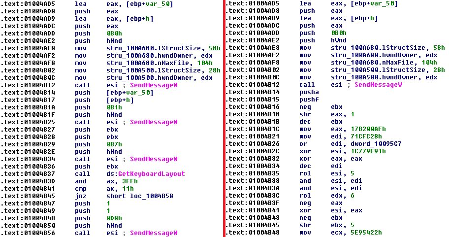
Figure 4. Comparison of the original Notepad binary code (left) and backdoor.
The component is a separate executable file designed to run the payload and the data eraser component.
The launch component contains a specific time and date. In the studied samples, two dates were set: December 17 and 20, 2016. As soon as one of the two dates comes, the component creates two streams. The first one tries to load the malicious DLL, the second one waits for one or two hours (depending on the version of the component), and then it tries to load the data eraser component. Both threads have the highest priority of
The name of the malicious DLL is added by the attackers through the command line parameter provided in one of the main backdoor commands (“Execute the shell command”). The name of the data eraser file is always
Each command line argument indicates the following:
•
•
•
•
The payload and data eraser component are standard Windows DLL files. To be loaded by the startup component, they must export the

Figure 5. An example of a malicious DLL with the internal name
The malicious DLL with the file name
Component 101 partially implements the protocol described in the IEC 101 standard. It is capable of communicating with the RTU and any other device that supports this protocol.
After execution, component 101 analyzes the configuration stored in the INI file. A configuration can contain several entries: process name, Windows device names (usually COM ports), number of ranges, and range values for information object addresses (IOA). An IOA is a number that identifies a particular data item in a device. In fig. 6 shows the configuration file of component 101 with two defined IOA ranges: 10-15 and 20-25.

Figure 6. Sample component configuration 101.
The name of the process specified in the configuration belongs to the application, which, as the attackers assume, works in the victim's system. This should be the application that the machine uses to communicate with the RTU over a serial connection. Component 101 attempts to complete this process and accesses the specified device using the Windows API functions
The component iterates over all IOA ranges. For each IOA, it creates packets of select and execute commands with a one-position (

Figure 7. Example of a disassembled payload packet in Kaitai Struct WebIDE.
The DLL with the file name

Fig. 8. Sample component configuration dll file 104.
After executing the DLL, component 104 will attempt to read the configuration file. The path to the configuration file is taken from the loader component.
The configuration contains a
Our analysis of this component shows the following possible configuration options:

After reading the configuration file, component 104 creates a process for each fragment of
The basic idea of using component 104 is relatively simple. It communicates with the specified IP and starts sending packets with the ASDU address specified in its configuration. The purpose of this data exchange is to communicate with IOA one-type commands. In the configuration file, an attacker can define the
The first such

Fig. 9. An example of a packet of component 104 decoded in Wireshark.
As soon as all possible IOAs from a certain range are polled, component 104 proceeds to the second stage of the
In fig. 10 shows the log file that component 104 issued during our analysis. From it, we see that the component interrogated IOA from 10 to 15 and, when IOA of the single-position type were detected, began their use in a loop. In the configuration, the

Fig. 10. Example of log component 104.
The second mode of
The third
In addition to the ability to write to the log, component 104 can output debugging information to the console, as shown in fig. eleven.

Fig. 11. The output to the console component 104.
Unlike components 101 and 104, it exists as a separate malicious tool consisting of an executable file called
After executing the DLL, the 61850 component tries to read the configuration file, whose path is provided by the launch component. A separate default version takes the configuration from
If the configuration file is not found, component 61850 numbers all connected network adapters to define their TCP / IP subnet masks. The component then numbers all possible IP addresses for each of the subnet masks and tries to connect to port 102 of each address. Thus, the component can automatically detect suitable devices in the network.
In another case, if the configuration file is found and contains the target IP addresses, the component connects to port 102 via these addresses and those found automatically.
As soon as this component connects to the target host, it sends a connection request packet using a connection-oriented transport protocol, as shown in Figure 2. 12.

Fig. 12 Decoded connection request packet in Wireshark.
If the target device responds properly, component 61850 sends the
This component 61850 then numbers the components found in the previous step and sends domain-specific

Fig. 13. Decoded MMS request
Then the 61850 component parses the information obtained in response to these requests, and searches for variables that contain the following string sequences:
The CSW sequence is the name of a logical node that is used to control circuit breakers and switches.
For variables that contain the Model or stVal sequences, component 61850 sends an additional MMS request
Component 61850 will create a file with its operation logs, containing IP addresses, MMS domains, named variables and the state of the nodes (open or closed) of its targets.
The OPC DA component implements the client for the protocol described in the OPC Data Access specification. OPC (OLE for Process Control) is a software standard and specification based on Microsoft technologies such as OLE, COM, and DCOM. The part related to data access (DA) of the OPC specification allows real-time data exchange between distributed components according to the client-server model.
This component exists as a separate malicious tool with the file name
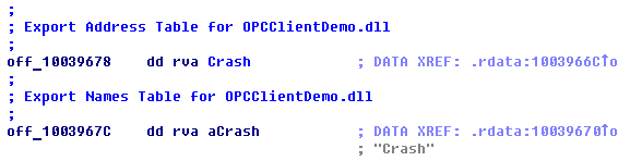
Fig. 14. Table PE shows the internal DLL name of the OPC DA component.
The OPC DA component does not require any configuration file. After an attacker executes, it numbers all OPC servers using the
The following component uses the
Element names suggest that the attackers are interested in OPC elements provided by OPC servers that relate to ABB solutions, such as the MicroSCADA line. In fig. Figure 15 shows a sample of OPC elements that contain names with similar string sequences. This list of OPC items is obtained from the OPC process object lists tool from ABB.

Fig. 15. An example of the names of OPC elements in the IN field, obtained with the tool of the lists of objects of the OPC process.
Attackers use the

Fig. 16. Disassembled code of the OPC DA component, which uses the
At the final stage, the OPC DA component tries to change the state of the detected OPC elements using the

Fig. 17. Disassembled code of an OPC DA component that uses the
The component writes the name of the OPC server, the state of the name of the OPC element, the quality code and the value in the log file. Recorded values are separated by the following header lines:
The Data Wiper component is a destructive component that is used in the final stage of an attack. Hackers use this component to cover their tracks and complicate the recovery process.
The file name of this component is
After execution, the component tries to number all the keys in the registry, which lists the Windows services.
It tries to set the value of the
The next step is to delete the contents of the file. The component numbers files with certain extensions on all drives connected to the computer, from C: \ to Z: \. It should be noted that during the numbering component skips files located in a subdirectory that contain the word
The component replaces the file contents with meaningless information obtained from the contents of the new allocated memory. To perform this operation properly, the component tries to rewrite the files twice. The first attempt occurs when the file is detected on the drive. If the first attempt is unsuccessful, the component makes a second attempt, but before that it terminates all processes, except those included in the list of critical system processes. The list of processes is shown in Fig. 18.
To speed up the erasing process, the component overwrites only part of the contents of the file at its beginning. The amount of information that will be rewritten depends on the size of the file.The smallest amount of information will be rewritten for files of 1 Mb (4096 bytes) and less. The largest amount of information will be rewritten for files of 10 Mb (32768 bytes) and less.
Finally, this component tries to terminate all processes, including system ones, except its own. This will cause the system to stop responding and eventually fail.

Fig. 18. List of processes that are not completed during the second attempt.
File name masks that the eraser component rewrites:
This list contains file name extensions that are used in a standard environment, such as Windows binaries (.exe / .dll), archives (.7z /.tar/.rar/.zip), backup files (.bak / .bk /. bkp), Microsoft SQL server files (.mdf / .ldf) and various configuration files (.ini / .xml). In addition, the component erases files that can be used in industrial control systems, for example, written using substation configuration description language (.scl / .cid / .scd), as well as files and extensions that are used by ABB products.
For example, a file called
The attacker's arsenal includes a port scanner, which can be used to map the network and search for computers related to their attack. What is interesting, instead of using existing software, hackers have created their own port scanner. As can be seen from fig. 19, they can assign a range of IP addresses and a range of network ports to be scanned by this tool.

Fig. 19. An example of using the port scanner.
Another tool from the hacker’s arsenal is a Denial of Service (DoS) tool aimed at Siemens SIPROTEC devices. The tool exploits the CVE-2015-5374 vulnerability to cause a device to hang. As soon as this vulnerability is exploited, the device will stop responding to any commands until it is rebooted manually.
To exploit this vulnerability, attackers have hard-coded IP addresses of devices in the DoS tool. When used, the tool sends specially created packets on port 50000 to the target IP address using UDP (User Datagram Protocol). The UDP packet contains only 18 bytes.

Fig. 20. The contents of the UDP packet involved in using the vulnerability CVE-2015-5374.
The investigation of power outages in Kiev in December 2016 has not yet been completed. At the moment there is no evidence that Industroyer was the direct cause of the failure. However, we believe this version is quite likely, since the malware allows you to directly control circuit breakers and circuit breakers in the network of electrical substations using ICS protocols, and also contains an activation time stamp on December 17, 2016, on the day of power failure.
We can safely say that the Win32 / Industroyer family is an advanced and sophisticated malware aimed at industrial control systems. The problem is that hardware is only a tool in the hands of even more advanced and highly skilled intruders. The cyber group behind Industroyer can adapt the program to any such environment.
The widespread industrial protocols that Industroyer uses were created decades ago without security considerations. Thus, any interference of hackers in the work of the industrial network, where these protocols are applied, will certainly lead to serious consequences.
SHA-1 hashes: IP addresses of C & C servers:
Attention!Most of the servers with these IP addresses were part of the Tor network, which means that using indicators can give a false positive match.
You can ask additional questions or submit malware samples related to Win32 / Industroyer by emailing threatintel@eset.com.
The creators of Win32 / Industroyer are distinguished by high qualifications and a deep understanding of industrial control systems and communication protocols in the power industry. It is unlikely that anyone could write and test similar software without access to specialized equipment used in the target environment.
')
The authors of the malware implemented support for four industrial protocols described in the following standards:
- IEC 60870-5-101 (IEC 101)
- IEC 60870-5-104 (IEC 104)
- IEC 61850
- OLE for Process Control Data Access (OPC DA)
In addition, the authors of Industroyer have developed a tool for performing DoS attacks (denial-of-service-denial of service) aimed at certain relay protection devices, in particular, the Siemens SIPROTEC line.
Win32 / Industroyer features are impressive. If you compare it with the tools that were used in attacks on the Ukrainian power grid in 2015 and led to massive power outages on December 23, 2015 (BlackEnergy, KillDisk and other components, including legitimate remote access software), it can be argued that there is a cyber group behind Industroyer higher level. The authors have created a malicious program that allows you to directly control switches and circuit breakers in a network of electrical substations. By some indications, we assume that Industroyer may be associated with a power outage in Kiev in December 2016. However, this was not confirmed at the time of writing the report, and the investigation is ongoing. The infection vector has not yet been established.
Industroyer consists of several modules, the description and analysis of which are presented in the following sections of the report. Before turning to the details, we offer a simplified diagram that shows the relationship between the components of a malicious program.
Figure 1. Simplified diagram of Win32 / Industroyer components.
Some components (including the data eraser) are similar in concept to the tools used in the BlackEnergy attacks on Ukrainian energy companies in 2015. However, we do not see the connection between past attacks and the code of the new malware.
Main backdoor
The main component of the Industroyer, the main backdoor, is used by attackers to control the rest of the program.
As befits a backdoor, this component is quite simple. It connects to a remote C & C server via HTTPS and receives commands from the attackers. All studied samples are hard-coded to use the same proxy address located in the local network. Thus, the backdoor is clearly designed to work in a particular organization. It is also worth mentioning that most backdoor C & C servers use Tor.
Perhaps the most interesting feature of the backdoor is that attackers can set a specific hour when the malware will be active. For example, you can modify the backdoor so that it accesses the C & C server during off-hours. This complicates detection based only on the inspection of network traffic. However, all samples studied so far worked around the clock.
Figure 2. Decompiled code of the main backdoor with the ability to set the time.
After connecting to the remote C & C server, the main backdoor sends the following data to the POST request:
- GUID string (globally-unique identifier) for the current hardware profile, obtained using the
GetCurrentHwProfilefunction - malware version - 1.1e
- hard-coded sample ID
- the result of any previously received command
A hard-coded ID is used by attackers as an identifier for an infected machine. Among all the samples studied, we found the following ID values:
- DEF
- DEF-C
- DEF-WS
- DEF-EP
- DC-2-TEMP
- DC-2
- CES-McA-TEMP
- CES
- SRV_WSUS
- SRV_DC-2
- SCE-WSUS01
The main backdoor supports the following commands:
Having obtained administrator rights, attackers can upgrade the installed backdoor to a more privileged version, which runs as a Windows service program . To do this, they need to select an existing non-critical Windows process and replace the
ImagePath registry parameter with the path to the new binary backdoor file.The functionality of the main backdoor, which runs as a Windows service, is identical to that described. But there are two small differences: the name of the version of the backdoor (1.1s instead of 1.1e) and the obfuscation of the code. The code for this version of the backdoor is mixed with unnecessary assembler commands.
Figure 3. Obfuscated assembler code for the main backdoor working as a Windows service.
Additional backdoor
An additional backdoor provides an alternative resiliency mechanism that allows attackers to restore access to the target network if the main backdoor is detected and / or deactivated.
The backdoor is a trojanized version of the Windows Notepad application. This is a full-featured application, but virus writers have added malicious code to it, which is executed every time it is launched. Further, having received administrator rights, attackers can manually replace malicious Notepad with legitimate ones.
The added malicious code is heavily obfuscated. After decryption, it connects to a remote C & C server (different from the C & C main backdoor) and loads the payload. It has a shellcode format that is loaded directly into memory and executed. In addition, the added code decrypts the Windows Notepad source code stored at the end of the file, and then passes execution to it — this is how the application works properly.
Figure 4. Comparison of the original Notepad binary code (left) and backdoor.
Launcher component
The component is a separate executable file designed to run the payload and the data eraser component.
The launch component contains a specific time and date. In the studied samples, two dates were set: December 17 and 20, 2016. As soon as one of the two dates comes, the component creates two streams. The first one tries to load the malicious DLL, the second one waits for one or two hours (depending on the version of the component), and then it tries to load the data eraser component. Both threads have the highest priority of
THREAD_PRIORITY_HIGHEST , which means they get a higher share of CPU resources.The name of the malicious DLL is added by the attackers through the command line parameter provided in one of the main backdoor commands (“Execute the shell command”). The name of the data eraser file is always
haslo.dat . The expected command lines are:%LAUNCHER%.exe %WORKING_DIRECTORY% %PAYLOAD%.dll %CONFIGURATION%.iniEach command line argument indicates the following:
•
%LAUNCHER%.exe is the name of the startup component file.•
%WORKING_DIRECTORY% - directory where the malicious DLL and configuration is stored•
%PAYLOAD%.dll is the name of the malicious DLL file•
%CONFIGURATION%.ini is the file in which the configuration data of a specific payload is stored. The path to this file is passed to the malicious DLL launch component.The payload and data eraser component are standard Windows DLL files. To be loaded by the startup component, they must export the
Crash function as shown in Figure. five.Figure 5. An example of a malicious DLL with the internal name
Crash101.dll and the exported Crash function.Component 101
The malicious DLL with the file name
101.dll is named after the international standard IEC 101 (aka IEC 60870-5-101 ), which describes a protocol for monitoring and controlling electrical power systems. The protocol provides communication between industrial control systems and remote terminal units (Remote Terminal Units - RTUs). Data is exchanged via serial connection.Component 101 partially implements the protocol described in the IEC 101 standard. It is capable of communicating with the RTU and any other device that supports this protocol.
After execution, component 101 analyzes the configuration stored in the INI file. A configuration can contain several entries: process name, Windows device names (usually COM ports), number of ranges, and range values for information object addresses (IOA). An IOA is a number that identifies a particular data item in a device. In fig. 6 shows the configuration file of component 101 with two defined IOA ranges: 10-15 and 20-25.
Figure 6. Sample component configuration 101.
The name of the process specified in the configuration belongs to the application, which, as the attackers assume, works in the victim's system. This should be the application that the machine uses to communicate with the RTU over a serial connection. Component 101 attempts to complete this process and accesses the specified device using the Windows API functions
CreateFile , WriteFile and ReadFile . The first COM port from the configuration file is used for the actual connection, the other two are open to prevent other processes from accessing. Thus, component 101 can take control of the RTU device.The component iterates over all IOA ranges. For each IOA, it creates packets of select and execute commands with a one-position (
C_SC_NA_1 ) and two-position command ( C_DC_NA_1 ) and sends it to the RTU device. The main purpose of the component is to change the value of the On / Off switch for the single-point and two-position IOA command type. So, at the first stage, the component tries to switch IOA to Off, to the second - On, at the final stage - to return to Off.Figure 7. Example of a disassembled payload packet in Kaitai Struct WebIDE.
Component 104
The DLL with the file name
104.dll is named after the standard IEC 104 ( IEC 60870-5-104 ). The IEC 104 protocol complements IEC 101 to transmit data over TCP / IP. Due to the flexible configuration, the component can be configured to attack under various equipment. Fig. 8 shows what the configuration file might look like.Fig. 8. Sample component configuration dll file 104.
After executing the DLL, component 104 will attempt to read the configuration file. The path to the configuration file is taken from the loader component.
The configuration contains a
STATION section, followed by properties that determine the operation of component 104. The configuration may contain multiple STATION entries.Our analysis of this component shows the following possible configuration options:
After reading the configuration file, component 104 creates a process for each fragment of
STATION , one for each. In each such process, component 104 will attempt to contact the specified IP address using the protocol described in IEC 104. Before establishing the connection, it will attempt to complete the legitimate process that should be responsible for communicating with the device. This happens only if the stop_comm_service property stop_comm_service registered in the configuration. By default, component 104 terminates the process with the name D2MultiCommService.exe , or with the name specified in its configuration.The basic idea of using component 104 is relatively simple. It communicates with the specified IP and starts sending packets with the ASDU address specified in its configuration. The purpose of this data exchange is to communicate with IOA one-type commands. In the configuration file, an attacker can define the
operation property to indicate how IOA addresses of a single position type will be polled.The first such
operation mode is range . Hackers use it to detect possible IOA in the device of interest. They have to apply this approach because the protocol described in the IEC 104 standard does not provide a definite method for obtaining this information.range works in two stages. During the first, after receiving the IOA range from the configuration file, component 104 connects to the target IP address and polls the specified IOA. To each of these IOAs, component 104 sends packets of select and execute commands to change state and check whether the given IOA is of a single-position command type.Fig. 9. An example of a packet of component 104 decoded in Wireshark.
As soon as all possible IOAs from a certain range are polled, component 104 proceeds to the second stage of the
range mode. If the ability to write to the logs is enabled, the component will write Starting only success . The rest of the second stage consists in an endless cycle of using previously detected single-position IOA type. In the loop, the component continuously sends packets of select and execute commands. In addition, if the change option is defined, the component switches the On / Off state between stages of the cycle.In fig. 10 shows the log file that component 104 issued during our analysis. From it, we see that the component interrogated IOA from 10 to 15 and, when IOA of the single-position type were detected, began their use in a loop. In the configuration, the
change option was turned on, so that between cycles the component switched the switch value from On to Off and wrote it to the log.Fig. 10. Example of log component 104.
The second mode of
operation is shift . It is very similar to range mode. The attacker defines the range of IOA and changeable values in the configuration file. After activating component 104, everything happens exactly the same way as in the range mode; however, as soon as all IOA in a certain range are polled, it begins polling a new range. The new range is calculated by adding the default range and the shift values.The third
operation - sequence mode. Can be used by hackers after they know the values of all IOA single-point type of commands supported by the connected device. This component will immediately begin executing an infinite loop, transferring the selection and execution packets to the IOA specified in the configuration file.In addition to the ability to write to the log, component 104 can output debugging information to the console, as shown in fig. eleven.
Fig. 11. The output to the console component 104.
Component 61850
Unlike components 101 and 104, it exists as a separate malicious tool consisting of an executable file called
61850.exe and DLL 61850.dll . Named after the IEC 61850 standard . This standard describes the protocol used to exchange data between devices from different manufacturers that perform the functions of protection, automation, measurement, monitoring and control of automation systems of electrical substations. This is a complex and reliable protocol, but component 61850 uses only a small number of its parameters to lead to devastating consequences.After executing the DLL, the 61850 component tries to read the configuration file, whose path is provided by the launch component. A separate default version takes the configuration from
i.ini . It is expected that the configuration file contains a list of IP addresses of devices that can communicate using the protocol described in the IEC 61850 standard.If the configuration file is not found, component 61850 numbers all connected network adapters to define their TCP / IP subnet masks. The component then numbers all possible IP addresses for each of the subnet masks and tries to connect to port 102 of each address. Thus, the component can automatically detect suitable devices in the network.
In another case, if the configuration file is found and contains the target IP addresses, the component connects to port 102 via these addresses and those found automatically.
As soon as this component connects to the target host, it sends a connection request packet using a connection-oriented transport protocol, as shown in Figure 2. 12.
Fig. 12 Decoded connection request packet in Wireshark.
If the target device responds properly, component 61850 sends the
InitiateRequest packet using the Production Message Specification (MMS). If the expected response is received, it sends an MMS request to getNameList . Thus, the component lists the names of the objects in the virtual production device (VMD).This component 61850 then numbers the components found in the previous step and sends domain-specific
getNameList requests with each object name. Thus, the component numbers the named variables in a specific domain.Fig. 13. Decoded MMS request
getNameList in Wireshark. Then the 61850 component parses the information obtained in response to these requests, and searches for variables that contain the following string sequences:
- CSW, CF, Pos and Model
- CSW, ST, Pos and stVal
- CSW, CO, Pos, Oper, but not $ T
- CSW, CO, Pos, SBO, but not $ T
The CSW sequence is the name of a logical node that is used to control circuit breakers and switches.
For variables that contain the Model or stVal sequences, component 61850 sends an additional MMS request
Read . For some of these variables, the component can also send an MMS Write request, which will change their current state.Component 61850 will create a file with its operation logs, containing IP addresses, MMS domains, named variables and the state of the nodes (open or closed) of its targets.
OPC DA component
The OPC DA component implements the client for the protocol described in the OPC Data Access specification. OPC (OLE for Process Control) is a software standard and specification based on Microsoft technologies such as OLE, COM, and DCOM. The part related to data access (DA) of the OPC specification allows real-time data exchange between distributed components according to the client-server model.
This component exists as a separate malicious tool with the file name
OPC.exe and DLL, which uses the functionality of both 61850 and OPC DA components. The internal name of the DLL in the exported PE table is OPCClientDemo.dll , which suggests that this component can be based on the open source project OPC Client .Fig. 14. Table PE shows the internal DLL name of the OPC DA component.
The OPC DA component does not require any configuration file. After an attacker executes, it numbers all OPC servers using the
ICatInformation::EnumClassesOfCategories with the category identifier CATID_OPCDAServer20 and IOPCServer::GetStatus to determine which ones are running.The following component uses the
IOPCBrowseServerAddressSpace interface to number all OPC server elements. In a special way, it searches for elements that contain the following sequences in the name:- ctlSelOn
- ctlOperOn
- ctlSelOff
- ctlOperOff
- \ Pos and stVal
Element names suggest that the attackers are interested in OPC elements provided by OPC servers that relate to ABB solutions, such as the MicroSCADA line. In fig. Figure 15 shows a sample of OPC elements that contain names with similar string sequences. This list of OPC items is obtained from the OPC process object lists tool from ABB.
Fig. 15. An example of the names of OPC elements in the IN field, obtained with the tool of the lists of objects of the OPC process.
Attackers use the
Abdul line when adding a new OPC group. Perhaps this line is used by attackers as a slang name for ABB solutions.Fig. 16. Disassembled code of the OPC DA component, which uses the
Abdul string.At the final stage, the OPC DA component tries to change the state of the detected OPC elements using the
IOPCSyncIO interface, setting the value 0x01 twice.Fig. 17. Disassembled code of an OPC DA component that uses the
IOPCSyncIO interface.The component writes the name of the OPC server, the state of the name of the OPC element, the quality code and the value in the log file. Recorded values are separated by the following header lines:
- [* ServerName:% SERVERNAME%] [State: Before]
- [* ServerName:% SERVERNAME%] [State: After ON]
- [* ServerName:% SERVERNAME%] [State: After OFF]
Data eraser component
The Data Wiper component is a destructive component that is used in the final stage of an attack. Hackers use this component to cover their tracks and complicate the recovery process.
The file name of this component is
haslo.dat or haslo.exe , it can be executed by the start component, or used as a separate malicious tool.After execution, the component tries to number all the keys in the registry, which lists the Windows services.
HKEY_LOCAL_MACHINE\SYSTEM\CurrentControlSet\ServicesIt tries to set the value of the
ImagePath registry with an empty string in each detected entry. This will cause the operating system to stop loading.The next step is to delete the contents of the file. The component numbers files with certain extensions on all drives connected to the computer, from C: \ to Z: \. It should be noted that during the numbering component skips files located in a subdirectory that contain the word
Windows in the name.The component replaces the file contents with meaningless information obtained from the contents of the new allocated memory. To perform this operation properly, the component tries to rewrite the files twice. The first attempt occurs when the file is detected on the drive. If the first attempt is unsuccessful, the component makes a second attempt, but before that it terminates all processes, except those included in the list of critical system processes. The list of processes is shown in Fig. 18.
To speed up the erasing process, the component overwrites only part of the contents of the file at its beginning. The amount of information that will be rewritten depends on the size of the file.The smallest amount of information will be rewritten for files of 1 Mb (4096 bytes) and less. The largest amount of information will be rewritten for files of 10 Mb (32768 bytes) and less.
Finally, this component tries to terminate all processes, including system ones, except its own. This will cause the system to stop responding and eventually fail.
Fig. 18. List of processes that are not completed during the second attempt.
File name masks that the eraser component rewrites:
- SYS_BASCON.COM
- * .v
- * .PL
- * .paf
- * .v
- * .XRF
- * .trc
- * .SCL
- * .bak
- * .cid
- * .scd
- * .pcmp
- * .pcmi
- * .pcmt
- * .xml
- * .CIN
- * .ini
- * .prj
- * .cxm
- * .elb
- * .epl
- * .mdf
- * .ldf
- * .bak
- * .bk
- * .bkp
- * .log
- * .zip
- * .rar
- * .tar
- * .7z
- * .exe
- * .dll
This list contains file name extensions that are used in a standard environment, such as Windows binaries (.exe / .dll), archives (.7z /.tar/.rar/.zip), backup files (.bak / .bk /. bkp), Microsoft SQL server files (.mdf / .ldf) and various configuration files (.ini / .xml). In addition, the component erases files that can be used in industrial control systems, for example, written using substation configuration description language (.scl / .cid / .scd), as well as files and extensions that are used by ABB products.
For example, a file called
SYS_BASCON.COMABB is used for storing information with a configuration, and files with an extension .paf( Product Authorization File) for storing information under licenses for ABB MicroSCADA products.Additional tools: port scanner
The attacker's arsenal includes a port scanner, which can be used to map the network and search for computers related to their attack. What is interesting, instead of using existing software, hackers have created their own port scanner. As can be seen from fig. 19, they can assign a range of IP addresses and a range of network ports to be scanned by this tool.
Fig. 19. An example of using the port scanner.
Additional Tools: DoS Tool
Another tool from the hacker’s arsenal is a Denial of Service (DoS) tool aimed at Siemens SIPROTEC devices. The tool exploits the CVE-2015-5374 vulnerability to cause a device to hang. As soon as this vulnerability is exploited, the device will stop responding to any commands until it is rebooted manually.
To exploit this vulnerability, attackers have hard-coded IP addresses of devices in the DoS tool. When used, the tool sends specially created packets on port 50000 to the target IP address using UDP (User Datagram Protocol). The UDP packet contains only 18 bytes.
Fig. 20. The contents of the UDP packet involved in using the vulnerability CVE-2015-5374.
Conclusion
The investigation of power outages in Kiev in December 2016 has not yet been completed. At the moment there is no evidence that Industroyer was the direct cause of the failure. However, we believe this version is quite likely, since the malware allows you to directly control circuit breakers and circuit breakers in the network of electrical substations using ICS protocols, and also contains an activation time stamp on December 17, 2016, on the day of power failure.
We can safely say that the Win32 / Industroyer family is an advanced and sophisticated malware aimed at industrial control systems. The problem is that hardware is only a tool in the hands of even more advanced and highly skilled intruders. The cyber group behind Industroyer can adapt the program to any such environment.
The widespread industrial protocols that Industroyer uses were created decades ago without security considerations. Thus, any interference of hackers in the work of the industrial network, where these protocols are applied, will certainly lead to serious consequences.
Infection Indicators (IoCs)
SHA-1 hashes: IP addresses of C & C servers:
F6C21F8189CED6AE150F9EF2E82A3A57843B587D
CCCCE62996D578B984984426A024D9B250237533
8E39ECA1E48240C01EE570631AE8F0C9A9637187
2CB8230281B86FA944D3043AE906016C8B5984D9
79CA89711CDAEDB16B0CCCCFDCFBD6AA7E57120A
94488F214B165512D2FC0438A581F5C9E3BD4D4C
5A5FAFBC3FEC8D36FD57B075EBF34119BA3BFF04
B92149F046F00BB69DE329B8457D32C24726EE00
B335163E6EB854DF5E08E85026B2C3518891EDA8
195.16.88[.]6
46.28.200[.]132
188.42.253[.]43
5.39.218[.]152
93.115.27[.]57
Attention!Most of the servers with these IP addresses were part of the Tor network, which means that using indicators can give a false positive match.
You can ask additional questions or submit malware samples related to Win32 / Industroyer by emailing threatintel@eset.com.
Source: https://habr.com/ru/post/330730/
All Articles