Copier RFID tags standard EM-Marin
As is known, many access systems use EM-Marin RFID cards with a frequency of 125 kHz. The intercom of my house was no exception. One problem - it would be nice to learn how to copy such cards, because the price tags for copying them are not encouraging. In the network, of course, there are quite a few copyist schemes (and the Chinese also sell their copyists for pennies - though they often put their password on the discs when copying), but why not put together your own copyist? This is the article below.
It is worth starting the development of a copyist with a clarification, and on what can such tags be copied? After reading the forums, you can find out that the most common blanks for copying are T5577, T5557, EM4305.
Now we need a scheme. Take the analog part of such a copyist from RECTO and connect it to the atmega8 microcontroller. Let's add a level converter to connect to a COM port based on max232 (those who wish can use ST232 or something else to connect via USB, but I have a COM port on my computer, as is the USB-COM adapter, so I have this task did not stand).
It turns out this scheme:
')
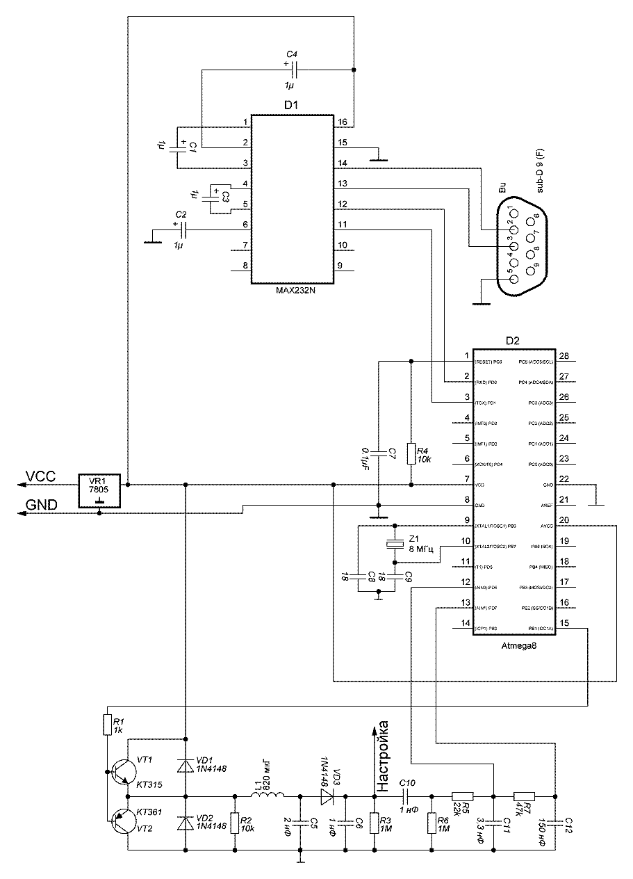
What is she like? Dual emitter follower, oscillating circuit, detector and RC-filters. Due to the fact that RC-filters have different time constants, comparing the voltage levels between the stages with each other, it is possible to isolate the change in the signal of the RFID tag. This task will be dealt with a comparator built into atmega8. The 125 kHz signal generation will be provided by the PWM controller built into the atmega8.
The combination of RFID tag - reader form a transformer, where the tag is a secondary winding. Information transfer tag is produced by changing the load of the secondary winding. As a result, the current in the reader coil (primary) changes. The selection of these current pulses and is engaged in the above analog part of the circuit. The oscillatory circuit must be set to the maximum voltage at the control point, for example, winding / winding the turns of the coil. True, it is said that the voltage is still better a little less than the maximum - it works more stable. I have a checkpoint of about 40 V.
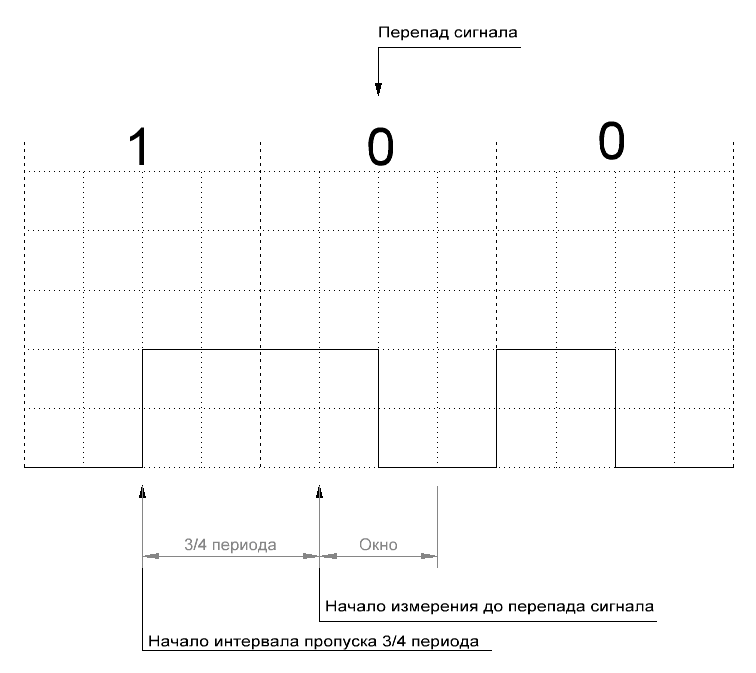
The copied label uses Manchester type coding. In order to decipher this code, it is enough to skip three-quarters of the bit slot period for any change in the signal's front and, following the signal difference following it, fix the bit value that will correspond to the signal value after the differential. When decoding, it is necessary to specify a window into which a signal drop should occur - no more than half the bit slot period.
The Manchester coding decoding method and the code for this I took from Shads . You could, of course, write your own, but I was in a hurry to launch the copyist - I wanted to make sure that the circuit was working and the tags were being received. So this fragment remained in the code of the copier. It also turned out that my comparator is configured inversely than the decoding code needs. Changed in the code. So, we received sequences of zero and units. How to get a card code from them?
A very simple. Assume that the card number by nibblám has the form AB CD EF GH IJ . The card gives this:
1) Nine units at the start;
2) Nibble A;
3) Nibbl parity A (1 bit);
4) Nibble B;
5) Nibbl parity B (1 bit);
...
16) Nibble I;
17) Nibbl I parity (1 bit);
18) J Nibble;
19) Nibbl parity J (1 bit);
20) Nibble parity columns for nibbles ABCDEFGHIJ;
21) Bit 0.
Read all 64 bits, decrypt and get 40 bits of card code. It is logical that if you give yourself this code, closing the coil of the card attached to the reader, we will get a card emulator. But now we are not interested in him.
We learned to read the map, but how to transfer the data to the map? To do this, simply turn on or off the frequency of 125 kHz in accordance with the protocol of exchange with the card. For the time of “silence” of the reader, the card is powered by stored energy.
The T5557 / T5577 blanks are fully compatible with each other according to the recording protocols, however, they have slightly different minimum and maximum pulse times (fortunately, the T5557 times overlap with T5577). The EM4305 has a different recording protocol.
To write T5557 I used the BolshoyK code. The table below shows the signal parameters for the T5557 key fob.
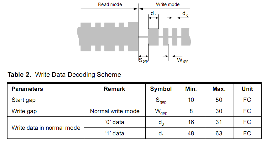
Recording starts with the StartGape signal — you need to turn off the 125 KHz signal for about 300 µs. This is a signal to the card that now it will begin to transmit data. Further information should be transferred to the disc. The coding of the transmitted data is the same Manchester.
The T5557 / T5577 and EM4305 blanks are multifunctional and can handle various types of modulations, support passwords and much more. Each blank on board has a set of blocks of 32 bits. The purpose of these blocks is different. In some, the key code that is issued (it takes up two blocks). In others, the configuration. Third - the manufacturer ID. We will use limited functionality, so those who want to understand what all these bits mean can look into the documentation for the blanks (I attached it to the archive).
Blocks are assembled in two pages (0 and 1).
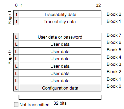
In the zero page there is a configuration block with an index of 0. We will set it. For T5557 / T5577 we will have the following configuration bytes: 0x00,0x14,0x80,0x40 in accordance with the table from the documentation (I marked in red with the modes selected with the unit bits):
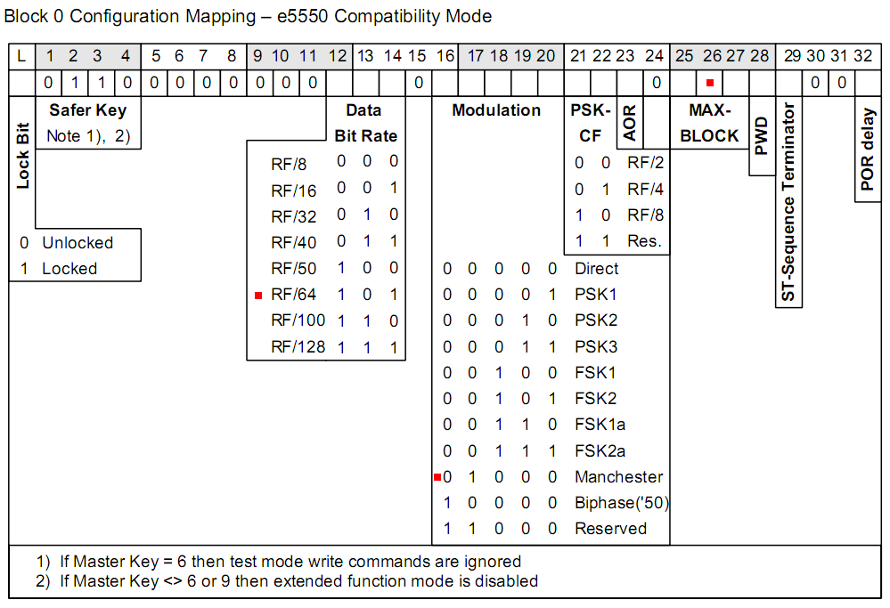
Thus, we have chosen: data transmission frequency RF / 64 (125 KHz / 64), Manchester type coding, block output to the second (in blocks 1 and 2 we will have the code issued by the card). Before recording, send the operation code (2 bits of opcode) and one bit of the latch (lockbit). The operation codes 10b and 11b precede the writing of data for pages 0 and 1 (the low-order bit specifies the page number, the most significant one - the page recording code). We have 10b for the opcode (all work goes with a zero page) and 0b for the bit of the latch. After transferring all this data, it is necessary to transfer the three-bit address of the recorded page. All data transmissions for the T5557 / T5577 are from the high bit to the low bit.
By specifying the card code in blocks 1 and 2 and the configuration in block 0, you can get a duplicate RFID tag. As you can see, everything is simple.
The next type of disc is EM4305. Here I had to deal with the recording of this disc myself. It also consists of blocks of 32 bits each, but their purpose is different.
Encoding of data transmitted to the card - by differences over the time interval. If the differential over the time interval was, then it is zero, and if it was not, it is one. The configuration word is stored in 4 bytes and for myself I defined it as: 0x5F, 0x80,0x01,0x00 (encoding Manchester, RF / 64, issuing the word 6). In words 5 and 6, I write down the card code (the 64 bits that the card produces). The EM4305 requires that the transmission be conducted from the low bit to the high bit. The card understands that they begin to exchange with it after issuing a combination of pulses to it:
The command to write a block to the card is transmitted as follows:
Command format
Command codes

Block address format
Thus, the configuration of the EM4305 blank and its code is specified.
Actually, nothing more is needed to a simple copyist.
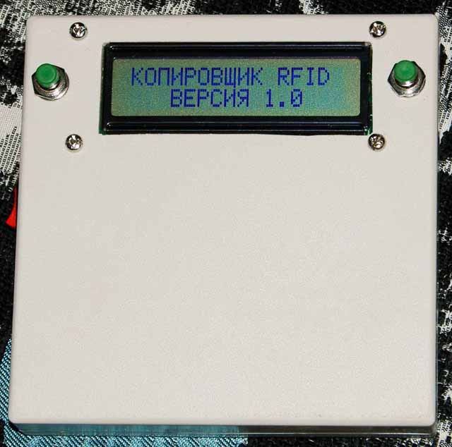
I made several copier options with different displays. For example, here is a copier with a 1602 display:
But the video of the copyist on the display LPH9157-02:
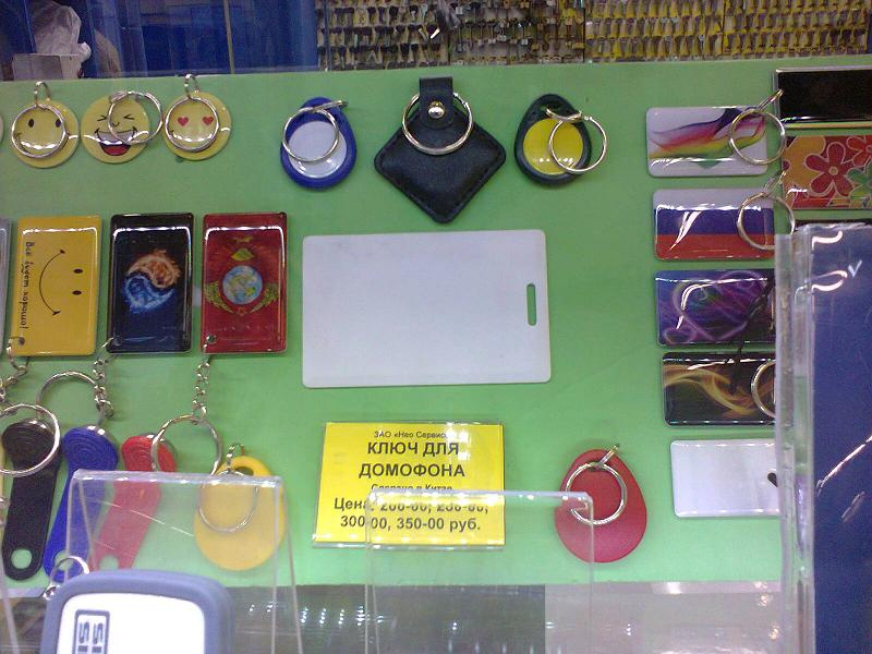
But the reason why I became interested in the copyists of such keys was to make many copies of the key of the intercom (it was too lazy to wait for a parcel from China), but this is the price tag:
In the archive all schemes, signets, programs and documentation for blanks. There is a version for Arduino Nano (it needs to be flashed separately through programs for uploading third-party firmware).
Those interested can open the documentation for all these discs and implement support for passwords and other modes of operation of the cards. I personally all this was unnecessary.
Special thanks to RECTO, BolshoyK and Shads - without you I would have had fun with the development for quite some time!
Thanks for attention.
PS I am not a professional in copying keys and in blanks, so I could be mistaken about something. However, the copyist works, and no one has yet found any errors in it.
It is worth starting the development of a copyist with a clarification, and on what can such tags be copied? After reading the forums, you can find out that the most common blanks for copying are T5577, T5557, EM4305.
Now we need a scheme. Take the analog part of such a copyist from RECTO and connect it to the atmega8 microcontroller. Let's add a level converter to connect to a COM port based on max232 (those who wish can use ST232 or something else to connect via USB, but I have a COM port on my computer, as is the USB-COM adapter, so I have this task did not stand).
It turns out this scheme:
')
What is she like? Dual emitter follower, oscillating circuit, detector and RC-filters. Due to the fact that RC-filters have different time constants, comparing the voltage levels between the stages with each other, it is possible to isolate the change in the signal of the RFID tag. This task will be dealt with a comparator built into atmega8. The 125 kHz signal generation will be provided by the PWM controller built into the atmega8.
The combination of RFID tag - reader form a transformer, where the tag is a secondary winding. Information transfer tag is produced by changing the load of the secondary winding. As a result, the current in the reader coil (primary) changes. The selection of these current pulses and is engaged in the above analog part of the circuit. The oscillatory circuit must be set to the maximum voltage at the control point, for example, winding / winding the turns of the coil. True, it is said that the voltage is still better a little less than the maximum - it works more stable. I have a checkpoint of about 40 V.
The copied label uses Manchester type coding. In order to decipher this code, it is enough to skip three-quarters of the bit slot period for any change in the signal's front and, following the signal difference following it, fix the bit value that will correspond to the signal value after the differential. When decoding, it is necessary to specify a window into which a signal drop should occur - no more than half the bit slot period.
The Manchester coding decoding method and the code for this I took from Shads . You could, of course, write your own, but I was in a hurry to launch the copyist - I wanted to make sure that the circuit was working and the tags were being received. So this fragment remained in the code of the copier. It also turned out that my comparator is configured inversely than the decoding code needs. Changed in the code. So, we received sequences of zero and units. How to get a card code from them?
A very simple. Assume that the card number by nibblám has the form AB CD EF GH IJ . The card gives this:
1) Nine units at the start;
2) Nibble A;
3) Nibbl parity A (1 bit);
4) Nibble B;
5) Nibbl parity B (1 bit);
...
16) Nibble I;
17) Nibbl I parity (1 bit);
18) J Nibble;
19) Nibbl parity J (1 bit);
20) Nibble parity columns for nibbles ABCDEFGHIJ;
21) Bit 0.
Read all 64 bits, decrypt and get 40 bits of card code. It is logical that if you give yourself this code, closing the coil of the card attached to the reader, we will get a card emulator. But now we are not interested in him.
We learned to read the map, but how to transfer the data to the map? To do this, simply turn on or off the frequency of 125 kHz in accordance with the protocol of exchange with the card. For the time of “silence” of the reader, the card is powered by stored energy.
The T5557 / T5577 blanks are fully compatible with each other according to the recording protocols, however, they have slightly different minimum and maximum pulse times (fortunately, the T5557 times overlap with T5577). The EM4305 has a different recording protocol.
To write T5557 I used the BolshoyK code. The table below shows the signal parameters for the T5557 key fob.
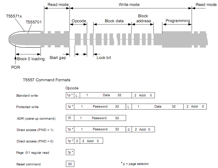
Recording starts with the StartGape signal — you need to turn off the 125 KHz signal for about 300 µs. This is a signal to the card that now it will begin to transmit data. Further information should be transferred to the disc. The coding of the transmitted data is the same Manchester.
The T5557 / T5577 and EM4305 blanks are multifunctional and can handle various types of modulations, support passwords and much more. Each blank on board has a set of blocks of 32 bits. The purpose of these blocks is different. In some, the key code that is issued (it takes up two blocks). In others, the configuration. Third - the manufacturer ID. We will use limited functionality, so those who want to understand what all these bits mean can look into the documentation for the blanks (I attached it to the archive).
Blocks are assembled in two pages (0 and 1).
In the zero page there is a configuration block with an index of 0. We will set it. For T5557 / T5577 we will have the following configuration bytes: 0x00,0x14,0x80,0x40 in accordance with the table from the documentation (I marked in red with the modes selected with the unit bits):
Thus, we have chosen: data transmission frequency RF / 64 (125 KHz / 64), Manchester type coding, block output to the second (in blocks 1 and 2 we will have the code issued by the card). Before recording, send the operation code (2 bits of opcode) and one bit of the latch (lockbit). The operation codes 10b and 11b precede the writing of data for pages 0 and 1 (the low-order bit specifies the page number, the most significant one - the page recording code). We have 10b for the opcode (all work goes with a zero page) and 0b for the bit of the latch. After transferring all this data, it is necessary to transfer the three-bit address of the recorded page. All data transmissions for the T5557 / T5577 are from the high bit to the low bit.
By specifying the card code in blocks 1 and 2 and the configuration in block 0, you can get a duplicate RFID tag. As you can see, everything is simple.
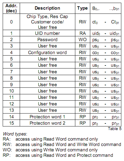
The next type of disc is EM4305. Here I had to deal with the recording of this disc myself. It also consists of blocks of 32 bits each, but their purpose is different.
Encoding of data transmitted to the card - by differences over the time interval. If the differential over the time interval was, then it is zero, and if it was not, it is one. The configuration word is stored in 4 bytes and for myself I defined it as: 0x5F, 0x80,0x01,0x00 (encoding Manchester, RF / 64, issuing the word 6). In words 5 and 6, I write down the card code (the 64 bits that the card produces). The EM4305 requires that the transmission be conducted from the low bit to the high bit. The card understands that they begin to exchange with it after issuing a combination of pulses to it:
- Turning off the field for 48 μs.
- We turn on the field for 96 μs.
- Turn off the field for 320 μs.
- Turn on the field for 136 μs.
- Disable the field to the next command.
The command to write a block to the card is transmitted as follows:
- We send the above sequence of pulses.
- We send 0b.
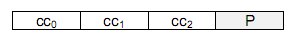
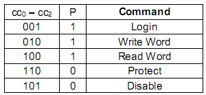
- We transfer CC0-CC1 and their parity P. (0101b for the record, see the tables below).
- We pass the address of the block (see table), two complementary zeros and the parity of the address.
- We transfer the block data (32 bits).
Command format
Command codes
Block address format
Thus, the configuration of the EM4305 blank and its code is specified.
Actually, nothing more is needed to a simple copyist.
I made several copier options with different displays. For example, here is a copier with a 1602 display:
But the video of the copyist on the display LPH9157-02:
But the reason why I became interested in the copyists of such keys was to make many copies of the key of the intercom (it was too lazy to wait for a parcel from China), but this is the price tag:
In the archive all schemes, signets, programs and documentation for blanks. There is a version for Arduino Nano (it needs to be flashed separately through programs for uploading third-party firmware).
Those interested can open the documentation for all these discs and implement support for passwords and other modes of operation of the cards. I personally all this was unnecessary.
Special thanks to RECTO, BolshoyK and Shads - without you I would have had fun with the development for quite some time!
Thanks for attention.
PS I am not a professional in copying keys and in blanks, so I could be mistaken about something. However, the copyist works, and no one has yet found any errors in it.
Source: https://habr.com/ru/post/330710/
All Articles