We generate arbitrary sequences on the findings of the Raspberry Pi board.
Author: Nikolai Khabarov, Embedded Expert DataArt, Evangelist for Smart Home Technologies.
In this article I will tell you how to write a standard user space-Python application for a modern ARM processor with Linux OS to generate complex sequences of impulses on board outputs. The idea is to use a processor DMA-module for copying from a previously prepared buffer in memory to GPIO with high accuracy in time.
')
When it comes to the need to generate a complex sequence of pulses, for example, for stepper motors, they usually use good old simple microcontrollers with a special real-time operating system installed or without an operating system at all. The implementation is, at best, written in C ++. Now the processors have made great strides and have a lot of advantages: performance, the ability to use the Linux operating system with all the infrastructure and software, as well as high-level programming languages such as Python. And yet, modern microcontrollers for generating complex sequences on GPIO pins, as a rule, are not used.
I implemented the pulse generation for controlling the stepper motors of the PyCNC project - a project of a CNC machine controller, machine tools, 3D printers, written entirely in Python and running on a modern ARM processor on the Raspberry Pi board.
The article may be useful to those who want to implement the generation of complex level setting sequences on the outputs of one or several GPIOs in other high-level programming languages using the DMA modules of other processors.
GPIO
General Purpose Input Output (GPIO) is a processor module that is responsible for setting the logic levels on the physical outputs. As you know, in the digital world on the output can be "0", i.e., the leg is attracted to the "ground" or "1", i.e. the leg is attracted to power.
Surely many of you have lit the LED, control one of the legs of the microcontroller. For example, in AVR microcontrollers, this was done by setting the corresponding bit in a variable, or, as it is often called, the PORTx register. What is this variable? If you look at the header files, there will be something like:
#define PORT (*(volatile uint8_t *)(0x12345678)) In other words, the output status record is a record of this value at a previously known address. Please note that this is not an address in RAM, moreover, not an address in the virtual memory of the process, it is an address in the address space of the processor itself. Physical, somewhere inside the chip, this address is connected to a real GPIO module, to which we access this address through the processor core, passing a byte of information to set the output state. And almost any processor has such modules. ARM-processor Raspberry Pi - is no exception. To find out exactly where each module is located in the address space, you need to look at the documentation of the processor you are interested in.
For Raspberry Pi, this document is here .
It contains the GPIO registers at the bus address 0x7E200000, in other words, by writing data to the corresponding addresses, you can control the status of the pins. Immediately, we note that all the peripherals of the Raspberry Pi 1, 2 and 3 processors are the same, only the physical addresses differ, in which the peripheral bus addresses are mapped, starting at address 0x7E000000. For version 1 of the Raspberry Pi, this will be 0x20000000, for versions 2 and 3 - 0x3F000000. That is, for the RPi3 processor, to access the bus address 0x7E200000, you need to write to the physical address 0x3F200000. In the documentation for the link above, all the addresses are bus addresses.
In most cases, Linux will be installed on the ARM processor. The question immediately arises how to access the physical memory. Access to it is in the core of the OS. We want to make a normal application running in a virtual address space. Fortunately, the Linux kernel provides access to the physical memory through the virtual device '/ dev / mem', by opening which (we need root privileges), we can write to the physical memory. To be fair, we note that in the official Raspberry Pi OS for Raspbian, there is also a device '/ dev / gpiomem,' provided by the driver 'bcm2835_gpiomem', access to which is even without superuser rights - access to the first GPIO register is immediately zero.
Let's practice a little bit, I think it will be easier to understand everything written above. Let's write a simple Python application that will light the LED connected to the GPIO21 pin running on Raspberry Pi 2 and 3 (for RPi1, correct the address in the listing). Instead of Python, you can use any other programming language that can call system functions from libc.so. Here is the actual code:
I left the magic numbers in the code intentionally - it would be easier to explain this way. Let's sort the code line by line.
The top five lines are the import of the required standard Python modules.
In the 7th line, we directly open the file '/ dev / mem' to access the memory.
In the 8th line, we call the memmap system function, which will project our, albeit virtual, file into the virtual address space of the process. That is, writing to the virtual memory of the process, we will actually write to the physical memory. The code also indicates the indent, starting from which address to project the memory, and the length (mmap.PAGESIZE). We specify the address of the first GPIO register and the length of one page of memory. At first glance it may seem that it is enough just to open '/ dev / mem', retreat to the desired address and start writing the file, but, alas, this will not work.
In the 9th line, we close the file, since we don’t have to keep the handle open, the mapping will not disappear anywhere.
In the 11th – 14th lines we read and write to the register with indentation 0x08. If you look at the documentation, this is the GPFSEL2 GPIO Function Select 2 register. With these registers, we choose what function the chip leg will perform. In this case, we set (first clear, then set using OR) 3 bits starting from the third at 001, so that the output works as an output. The fact is that there are quite a few conclusions to expose various modes, one register is not enough, so the registers are divided into groups of 10 conclusions each - hence this magic with numbers.
In the 16th and 22nd lines, we install a handler, waiting for Ctrl + C on the keyboard to exit the program.
On the 17th line, we run an infinite loop.
In the 18th line, we translate the output to a high state by writing a bit mask to the GPSET0 register.
On the 19th and 21st lines, we realize a half second delay.
In the 20th row, we translate the output to a low state by writing the GPCLR0 bit mask.
On lines 25 and 26, we tidy up after ourselves: we deinitialize the pin, translating into the default state - the input - and close the memory mapping.
A small note: the BCM2835 does not have registers similar to PORTA, like the AVR, that is, we cannot immediately record the state (high or low level) of all the pins at once. There is only the SET register, which allows you to set logical units on all pins, where units are in the bit mask, and the CLEAR register, which allows you to set logical zeros on all pins, where ones are in the bit mask.
By running this code with superuser privileges on Raspberry Pi 2 or 3, for example, via the command 'sudo python gpio.py', and connecting the LED to pin 21, we will see that it is flashing.
If you need a ready implementation of GPIO pin management, you can use the GPIO class from this file .
Stepper motors
Control of stepper motors is not so simple as it may seem at first glance. Let's take a brief insight into the essence of the problem and see why there is a need to generate such sequences at all. We will not go into the details of the theory of the device of a stepper motor, those who wish can read about it here .
Instead, we will immediately turn to reality, where a stepping motor has 4 or 5 leads from four windings. The currents needed to rotate the motor are quite large — not a single microcontroller or processor can provide such. Also, to create such currents, you need a voltage that is usually higher than the voltage of the processor logic. Therefore, with stepper motors used specialized chips - drivers, sometimes even integrated into the motor housing. The simplest drivers (for example, ULN2003) simply provide low-current winding control inputs compatible with standard microcontroller logic voltages. With such a driver, it is necessary to generate a sequence of pulses for each winding. Most of the drivers, including some of the most popular A4988 and DRV8825, take all the headache to work with the motor windings. They provide a simple interface with two low-current pins, STEP and DIR. As you can guess from their names, when a pulse is applied to STEP, the driver moves the engine one step (the driver can also be configured for so-called microsteps, i.e. movements 1/2, 1/4, etc. of the step - this is achieved techniques for working with windings). The DIR pin is used to select the direction of rotation of the engine, depending on whether a low or high level is applied to it.
The typical A4988 switching scheme looks like this (I borrowed the picture on the Internet):

In the simplest case, it is possible, by applying pulses to the STEP terminal, to rotate the engine with a certain frequency. Just to play with him is enough. But the laws of physics act on a real device, and it is impossible to instantly accelerate an engine to the required speed, simply by applying pulses with a fixed frequency, it is impossible if you do not want to break the mechanics. It is necessary to spin the engine with a certain acceleration to the desired speed, and then slow it down to a complete stop. Therefore, the pulse repetition frequency should change during acceleration and acceleration, and the required signal should no longer be periodic.
This approach to the control of motors with STEP and DIR pins is the most universal, since such a connection allows realizing almost any delights on the microcontroller itself. For example, the reader may be asked if there are drivers with I2C or UART-interface? Theoretically, such a driver can be made, but to control the same 3D printer, you need to synchronously control several stepper motors. Moreover, each of them may have different acceleration parameters, the number of steps per millimeter, maximum speeds. As a result, a similar driver in its complexity would be analogous to the CNC controller (CNC).
As you might have guessed, the GPIO control method described above cannot achieve the correct formation of impulses on pins. It's not just that delays in executing Python code are unpredictable. Even if you implement everything in C and in the form of a Linux kernel OC, we will not achieve a good result, since Linux is not a real-time operating system. At any time, the processor cores can switch to performing some other task, and we will not give impetus in time. But unless such trifles can stop us on the way to what was intended!
DMA
Direct Memory Access is a specialized hardware processor module that allows you to copy memory from one place to another without resorting to the services of the cores of the CPU itself. Such modules exist even in simple microcontrollers, but the implementation varies greatly from one processor model to another. The Raspberry Pi implementation is pretty mediocre - it has everything you need, but no frills. And, for example, the Rockchip RK3399 DMA-module is more like a mini-processor core with its own, albeit small, set of instructions.
I do not set myself the task of writing a complete translation of the original documentation. And I’ll tell you only about the main registers, which will allow us to launch the DMA-module in the mode of copying data into the GPIO-module.
As you could imagine, we will generate a buffer in memory and copy it to the address of the location of the GPIO module. But for the DMA module to work, it is necessary that this buffer be located somewhere in the physical memory. Naturally, any virtual memory, if it does not fall into the swap, will also be in physical memory. Using '/ proc / self / pagemap' you can get the memory mapping table of your own process into physical memory, that is, allocate a buffer and then find its physical address.
But you shouldn’t do this with DMA - all because of the same possibility of memory getting into the swap and the fact that the operating system memory manager can transfer your allocated memory to another place. You can write a simple nuclear module that, when loaded, calls a method from the Linux kernel kmalloc () - this method allocates and also blocks memory from possible transfers. Then you give the application the address of the allocated memory, for example, through a virtual device. Having this address, the application can access memory using the exact same method described in the GPIO section. The address or buffer we allocated can be used with the DMA module.
But you probably will not want to write a core module, even if it is extremely simple.
Well, there is a ready-made solution - the virtual device '/ dev / vcio'. It is created by the Raspberry Pi video card driver. For communication VideoCore and the CPU uses the so-called mailboxes, which, in fact, pieces allocated in the memory allocated for the video card. By default, the video card is allocated 64 MB, and if desired, this value can be changed. The fact that we will allocate some resources from the video memory for our needs will not affect the work of the video card, the main thing is not to take too much away. In practice, 30-35 MB of memory is enough for normal functioning of the Raspbian OS desktop, that is, about half. So the second half is fully accessible to us if we do not plan to run applications using OpenGL. Moreover, allocating a part of the memory for transfer to the GPU itself is a regular procedure. And, if we allocate memory, but do not give it to the video processor, there will be no problems. Here is an official example that uses this kind of memory allocation.
This process is rather trivial, although it is hidden behind the magic numbers in the code. Open / dev / vcio, then, using the ioctl () method, pass the structure with the request and get the answer. We need to allocate memory and block it so that the memory manager will not drag away the piece we have selected. You can see the implementation of the link above, we are interested in the methods mem_alloc (), mem_lock () and, of course, the methods that allow you to tidy up the mem_unlock (), mem_free (). If you are confused by the implementation in C, you can rewrite these methods to any other language.
Oh well. We found the place where to allocate the buffer. Now you need to somehow program the DMA so that it performs what we want. Once again, the DMA module is just a few registers in physical memory. It is managed in the same way - by recording the structures at the necessary addresses. In total, the Raspberry Pi has 16 DMA channels. The first eight are fully functional, the other eight are somewhat limited in functionality. Each channel has its own set of registers. The base address of the DMA bus of the module is 0x7E007000, i.e. for the Raspberry Pi 2 or 3 you need to write to the address 0x3F007000. Here is the first register of the first DMA channel. Each subsequent is located with a shift of 0x100 (with the exception of 15, it is located at 0x7EE05000).
What kind of channel to use? The choice is rather complicated, since the channels can be used by the core. You can find out which channels are used from the kernel itself via sysfs with the command 'cat / sys / class / dma / dma0chan * / in_use'. As a rule, you should avoid using 0, 1, 2, 3, 6, 7 channels, since they are used by a microSD card reader and a video card driver.
The main registers for controlling the DMA module are CS and CONBLK_AD. It is by filling them in, we run DMA. The first register is CS, in which we are interested in the fields:
| Bit number | Field | Description | Access |
|---|---|---|---|
| 31 | RESET | The unit record resets the DMA module. | W |
| one | END | When the unit is written, the transmission end flag is reset. | W |
| 0 | ACTIVE | When writing units, DMA will start working. Using this field You can pause DMA. After the end of the transfer field will automatically take the value 0. | Rw |
There are much more fields in the registers; an inquisitive reader can find a description of each of them in the official document by the link that we met above on page 47.
An address is written to the CONBLK_AD register, in which lies the so-called control block, which describes what the DMA module should do. At the same time, control blocks are a linked list, i.e. with the help of several control blocks, one can build a chain of different tasks. DMA-module, completing the task, automatically passes through all control blocks. It is from the address in CONBLK_AD that the DMA module will start copying when the ACTIVE bit is set in the CS register.
The control block must be stored in memory with alignment of 32 bytes (the 5 low bits of the address must be zero). And now let's see how the control block is arranged:
| Indent byte | Field | Description |
|---|---|---|
| 0 | Ti | A set of various flags that specify the parameters for copying data. |
| four | SOURCE_AD | Source address from which to start copying. |
| eight | DEST_AD | Destination address to copy. |
| 12 | TXFR_LEN | The number of bytes to copy. In a special 2D mode, the upper 16 bits set number of copy cycles, lower 16 bits - The number of bytes to copy per cycle. |
| sixteen | STRIDE | Used only in 2D mode. Low 16 bytes store a sign number that specifies how much to move source address before the next cycle. The upper 16 bytes store the sign number you need move the destination address before the next cycle. |
| 20 | NEXTCONBK | Pointer to the next control block. |
Channels 0 to 7 support 2D mode (set by the TDMODE flag (bit 1) in the TI field of the control block), which allows you to organize X copies by Y bytes. At the same time, the destination and / or source addresses can be increased / decreased by a certain amount before each copying, according to the STRIDE field in the control block.
Each DMA channel also has a set of registers TI, SOURCE_AD, DEST_AD, TXFR_LEN, STRIDE, NEXTCONBK, which can only be read. They are loaded from the current control unit.
Well, let's try to do something simple with DMA and GPIO modules in Python. So that the listing of the program is not tediously long and does not contain unnecessary magic numbers, let's take some ready-made code from this file .
From it, we will use constants and the classes 'PhysicalMemory' (access to physical memory, as we did in the example with GPIO) and 'CMAPhysicalMemory' (this is the implementation of allocating physical memory using the video driver / dev / vcio, which we wrote above) .
When you start this program (do not forget to run with superuser rights), the LED connected to the 21st pin lights up for half a second at full brightness (so that the difference is noticeable), and then it will glow at half brightness until you press the enter key . Let's break down line by line.
2–3 lines - import of modules.
5th and 6th - variables indicating which DMA channel and GPIO output we use.
8–15th — we initialize the specified GPIO output as an output and light it for half a second (so that the difference is noticeable when the DMA is turned on). In essence, this is the same thing that we did in the first program, but written at a slightly higher level.
17th line - we ask the video driver to allocate us 64 bytes in memory. In the CMAPhysicalMemory class, memory is allocated with alignment equal to the page size, that is, 4096 bytes, therefore when using this memory, the beginning of the allocated memory will also always be aligned with the 32 bytes that are required by the DMA module.
18th line - we fill the first structure of the control block. On this dwell a little more.
19th line - the first 4 bytes - TI flags (Transfer Information). DMA_TI_NO_WIDE_BURSTS — burst- — — , , .
DMA_TI_WAIT_RESP — DMA- .
DMA_TI_SRC_INC DMA_TI_DST_INC — , DMA- 4 . , DMA-, / . .
20- — , . , , () ( get_bus_address()). , , , . .
21- — GPIO- SET, . . , .
22- — — 4 .
23- — stride, , 0.
24- — next control block, 32 .
25- — , , 21- 4 , , — , GPIO.
26 — .
28–37- — , . CLEAR GPIO, . , .
38–39- — .
41- — DMA- .
42-43- — DMA-.
44- — .
45- — DMA-.
47- — Enter.
49–52- — . DMA- ().
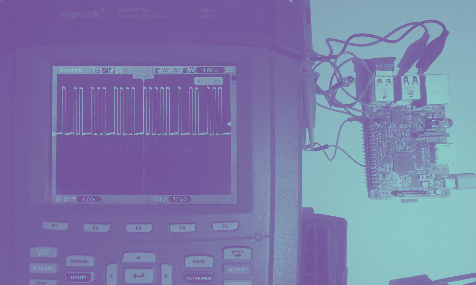
, :

Raspberry Pi 2. , 1.5 — ( ~2 ) , , .
DMA
, , — DMA- GPIO-. DMA — , , … , .
DMA 1 . , STEP, , , 2 . , 2 , . . 500 000 . 4 , . : 1 ( 200 200 / — ), 114 . — 228 . , ? , , . 114 .
DMA- — . DMA- — . , , , , , , 16 4 . , . . - , . , , .
GPIO DMA , - . , 3D-. . ?
.
:

, GPIO, DMA ( ). « 1» , « 2» — . . 200 200 /. « 2», . , , . . , . CNC- .
(200 400 — 80 000 ) 128 ( 32 ), DMA ~9.8 . . , , . 3D- , . . 39.2 , , ( - ), .
, ? , , , . . GPIO . DMA- — . PWM (, , , ). PWM , , DMA FIFO- PMW. PWM- . , PWM , FIFO.
DMA- PWM-, PERMAP TI , , 5, PWM- .
, , DMAGPIO. rpgpio, , ( 1, 2, 3, 4 5 ). :

, , , .
import rpgpio PIN=21 PINMASK = 1 << PIN PULSE_LENGTH_US = 1000 PULSE_DELAY_US = 1000 DELAY_US = 2000 g = rpgpio.GPIO() g.init(PIN, rpgpio.GPIO.MODE_OUTPUT) dma = rpgpio.DMAGPIO() for i in range(1, 6): for i in range(0, i): dma.add_pulse(PINMASK, PULSE_LENGTH_US) dma.add_delay(PULSE_DELAY_US) dma.add_delay(DELAY_US) dma.run(True) raw_input("Press Enter to stop") dma.stop() g.init(PIN, rpgpio.GPIO.MODE_INPUT_NOPULL) DMA-
DMA-, , FM- Raspberry Pi — .
DMA-, 250 . , DMA- . . PWM ( PWM , PWM- ), . , , . , DMA-, PWM-, , .
PRU
BeagleBone PRU (programmable real-time unit), 200 32- , AM3358. . . — .
Conclusion
DMA- , , .
, , . , . Raspberry Pi Zero, , .
— , , :
Source: https://habr.com/ru/post/330536/
All Articles