TSic digital temperature sensor: addresses, passwords, turnout
We continue a series of materials about the features of the use of various sensors and sensitive elements.
 The hero of today's article, at first glance, is nothing special - have we seen enough digital temperature sensors. However, the TSic series has two unusual properties: really high accuracy (up to ± 0.07 ° C for the older model) and the little-known single-wire ZACwire interface.
Under the cat we describe in detail the nomenclature of standard TSic sensors and custom solutions, understand the features of the communication protocol, see examples of programs for the MC. In short, we are doing everything to convince a respected reader that TSic sensors are worth their money.
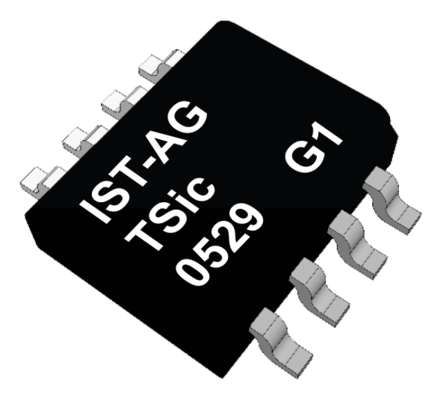
TSic is a series of digital temperature sensors, which in the past were manufactured under the ZMDI brand, and now belong to the Swiss company IST AG.
')
A sensitive element of the sensor is a high-precision reference voltage source with an output proportional to temperature (bandgap reference with a PTAT (proportional-to-absolute-temperature). Like other integrated temperature sensors, TSic also contains an ADC, signal processing circuit, EEPROM with data for calibration and output interface.
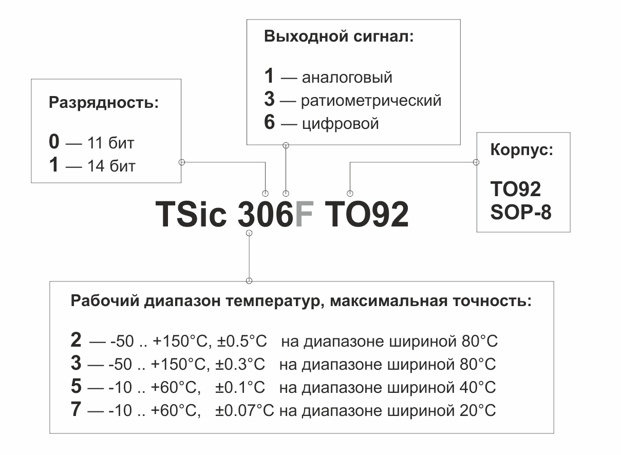
Standard TSic sensor models differ among themselves in their working temperature range, accuracy, type of output signal and housing.
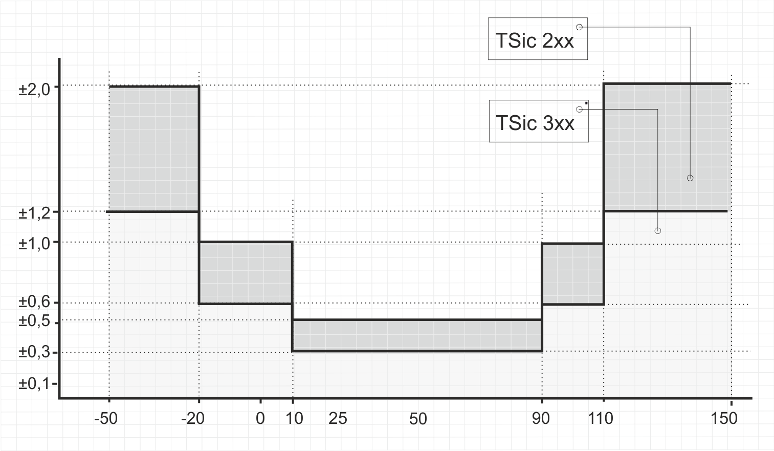
TSic 20x and TSic 30x sensors have a working temperature range from -50 to + 150 ° C and three “precision zones”. The graph shows the maximum error of the sensors at different temperature ranges.
TSic 50x sensors are designed for a narrower temperature range - from -10 to + 60 ° C. On a 40-degree wide precision section, TSic 50x sensors provide ± 0.1 ° C accuracy, and on the rest of the range - ± 0.2 ° C.

The mostexpensive TSic high-precision sensor is the TSic 716 model. In a narrow 20-degree area, this element provides ± 0.07 ° C.

The difference with the TSic 716 sensor is also a higher bit depth (resolution). If the TSic 206, TSic 306 and TSic 506 sensors have an 11-bit ADC integrated, then the TSic 716 is equipped with a 14-bit converter.
Thus, the resolution of the TSic 206 and TSic 306 sensors is ,
TSic 506 resolution is ,
TSic 716 resolution is .
The standard TSic sensor designs are described above, however, the range of the increased accuracy of any of the TSic sensors can be “shifted” during the production of an element. For example, TSic 50x sensors are available on request with increased accuracy in the area from -10 to 30 ° C or from 13 to 53 ° C. Similarly for other TSic models.

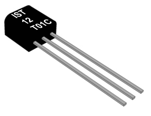
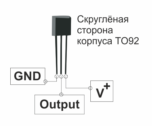
TSic sensors are available in SOP-8 and TO92 packages, pinout is available in the documentation .
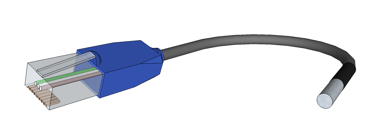
In addition, it is possible to supply TSic sensors in non-standard enclosures, with all sorts of cables, connectors, pads and so on. Everything is discussed individually here, but I must say right away that in order to use this opportunity it is not necessary to have a project for hundreds of sensors a year.
To connect any TSic model, you need power and ground connections, as well as one signal line.
The operating voltage of the sensor is from 3 to 5.5V. Often it is more convenient to power the sensor from one of the GPIO controllers. Firstly, it allows to reduce the power consumption of the sensor outside the measurement cycle to zero, and secondly, the detection of the beginning of the package is simplified if the TSic sensor with a digital output is used.
If the sensor is powered from the controller's foot, the manufacturer recommends taking care of eliminating the influence of noise and adding an RC-chain to the power line.
TSic 20x, TSic 30x and TSic 50x sensors can be analog, ratiometric or digital output. In the first case, the output voltage varies from 0 to 1 V proportional to the temperature of the medium, in the second case - from 10 to 90% of the supply voltage. Sensors with digital output use the ZACWire protocol, which we will discuss in detail below.
In all three cases, the output signal is proportional to the temperature, i.e. simple formulas are used to calculate the temperature.
For TSic sensors with analog output:
For TSic sensors with ratiometric output:
For TSic sensors with digital output:
Where
Examples of the output signals of TSic sensors are given in the table.
Most often, however, choose sensors with digital output, it allows you not to think about the effect of analog signal processing circuits on the measurement accuracy. In this case, the TSic digital sensor uses as many legs of the MK as the analog sensor, plus it is a bit cheaper.
The obvious minus of a TSic sensor with a digital output is a non-standard interface for which your MC does not have a ready-made library yet. The obvious advantage is that this interface is very simple.
ZACWire is a single-wire protocol using a coding that resembles a Manchester one.
A sensor with a predetermined frequency transmits data on temperature - two eight-bit data packets. Each packet starts with a start bit and ends with an even parity bit. Depending on the sensor model, in each parcel either 11 or 14 significant digits, the first bit goes first.

The passive state of the data line is high. Each bit of a TSic package starts with a signal decay and takes 125 microseconds. The state of the data line is fixed in the middle of this interval - if after 62.5 microseconds the signal falls on the high level, then we write a logical "1", if low, then a logical "0". The fill ratio in the first case is 75%, in the second - 25%.

The ZACWire communication interface does not use a separate clock signal, so the clock is counted on the side of the microcontroller.
The start bit also starts with a drop in signal, but has a fill factor of 50%. The start bit can be used both to detect the beginning of a parcel and to measure the duration of a clock if it is not known in advance: the time period between the decay and the front of the start bit is T strobe , the time after which the line should be checked when reading the next bit.
On the other hand, for standard TSic sensors, the value of T strobe is known in advance.
and is equal to 125/2 = 62.5 µs, therefore, in practice, the start bit is simply detected and passed.

Parity bits are decoded in the same way as data bits. In the absence of external interference and a small connection length (up to 2 meters), integrity monitoring is usually not required. Between the end of the first packet and the second start bit, the line is set high.
To bring final clarity, consider an oscillogram of a TSic 306 sensor data packet.

The sending starts with the start bit, then there are insignificant data bits, which are always equal to “0”, then the high-order data bits are followed by “011”, then the parity bit, respectively, equal to “0”. The second packet starts after one period (T strobe * 2) and contains the start bit, eight low data bits “00011000” and parity bit, respectively, equal to “0”.

As a result, we obtain 01100011000bin = 792dec at the output and calculate the temperature value using the above formula.
If we talk about the frequency with which the TSic sensor transmits such parcels with data, then it is set during the production of the component and cannot be changed in the course of using the sensor. For TSic 206, TSic 306, TSic 506 models, the frequency is 10 Hz, for TSic 716 - 1 Hz. Sensors with non-standard measurement frequency - 250, 10, 1 and 0.1 Hz are available on request.
If the task does not involve polling the sensor as often as possible and there is a free line on the microcontroller, then it makes sense to use this line to power the sensor. Thus, whenever you need to receive data from the sensor, you can power up the sensor and expect a drop in the data line - the start bit of the first packet. Less than 85 microseconds will pass between the power supply to TSic and the transmission of the parcel, and after receiving two data packets, the sensor power can be turned off.
This is the way to connect the sensor used by your humble servant.
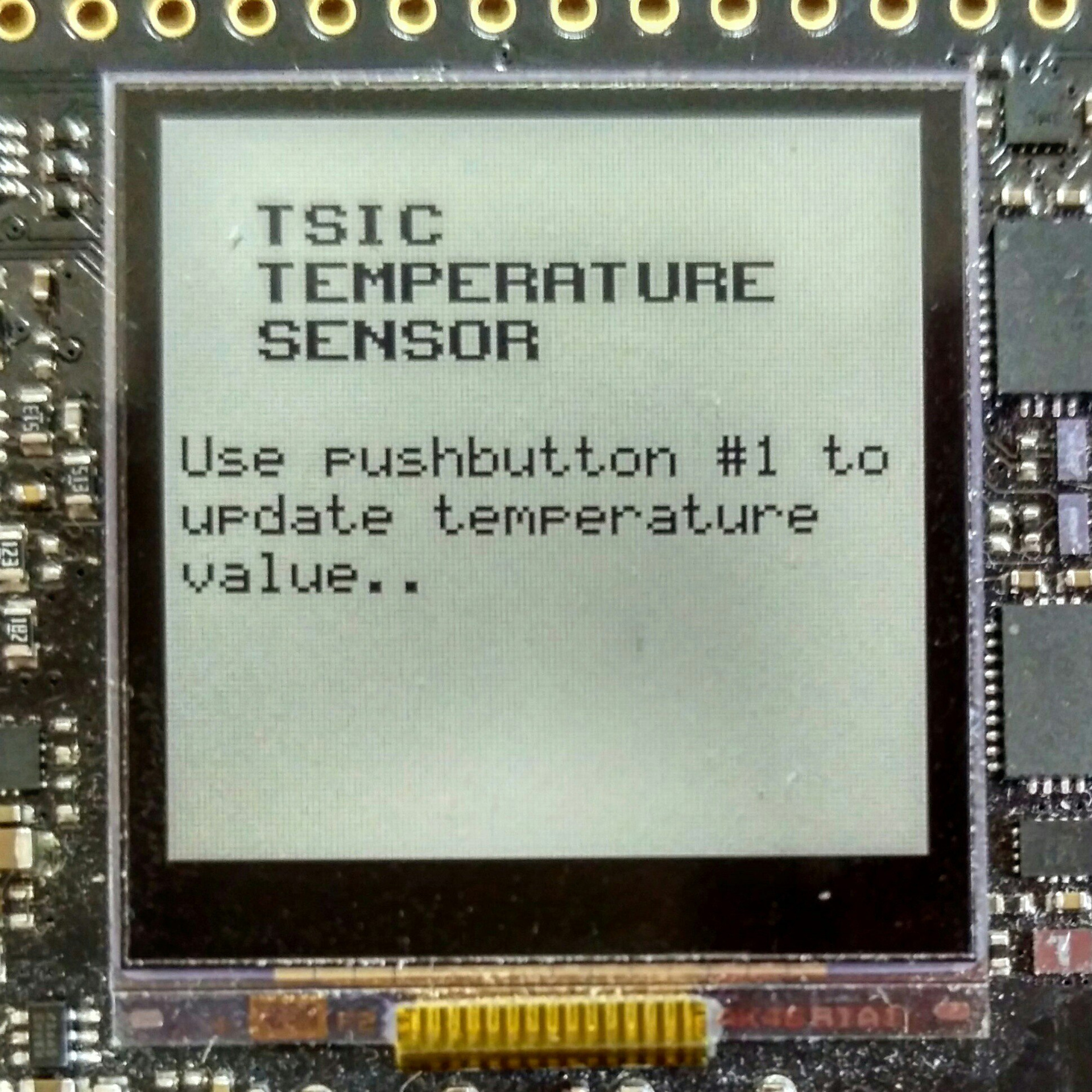
As an experiment, I connect two standard models TSic 306 TO92 and TSic 506 TO92 to the debug board EFM32ZG-STK3200. By pressing the button, the sensor is powered, one package with temperature data is received, the data is processed, the result is displayed on the LCD display installed on the board, after which the sensor is disconnected from the power supply.
Today, we generally will not deal with specific software and hardware components of the EFM32, designed to control and reduce energy consumption. Instead, we will use the most basic components and their modes of operation, so that the resulting algorithm can be more easilytransferred to the godless STM port to other microcontroller platforms.
So, from MK we need
On the debug board, respectively, we use
So, by interruption from the button, we supply power to the sensor, accept the parcel and turn off the power. If an error occurred while receiving data, we issue a corresponding message, otherwise we calculate the temperature in degrees Celsius and show the result on the LCD.
So, the receiveTSicData () data reception function is the reception of two data packets, the isolation of the parity bit from each of them, and the integrity check for both packets.
The readTSicPacket () function, which returns the currentTSicPacket, might look like this.
The settings of the microcontroller and the timer itself depend too much on the platform used to bring them in the text of the article about the sensor.
The integrity check functions and temperature calculations in degrees Celsius also do not constitute anything remarkable.
The code is completely available by reference .
In conclusion, I traditionally thank the reader for his attention and remind you that questions about the use of products, about which we write on Habré, can also be asked by email, specified in my profile.
The hero of today's article, at first glance, is nothing special - have we seen enough digital temperature sensors. However, the TSic series has two unusual properties: really high accuracy (up to ± 0.07 ° C for the older model) and the little-known single-wire ZACwire interface.Under the cat we describe in detail the nomenclature of standard TSic sensors and custom solutions, understand the features of the communication protocol, see examples of programs for the MC. In short, we are doing everything to convince a respected reader that TSic sensors are worth their money.
TSic is a series of digital temperature sensors, which in the past were manufactured under the ZMDI brand, and now belong to the Swiss company IST AG.
')
A sensitive element of the sensor is a high-precision reference voltage source with an output proportional to temperature (bandgap reference with a PTAT (proportional-to-absolute-temperature). Like other integrated temperature sensors, TSic also contains an ADC, signal processing circuit, EEPROM with data for calibration and output interface.
Standard TSic sensor models differ among themselves in their working temperature range, accuracy, type of output signal and housing.
Operating temperature range and accuracy
TSic 20x and TSic 30x sensors have a working temperature range from -50 to + 150 ° C and three “precision zones”. The graph shows the maximum error of the sensors at different temperature ranges.
TSic 50x sensors are designed for a narrower temperature range - from -10 to + 60 ° C. On a 40-degree wide precision section, TSic 50x sensors provide ± 0.1 ° C accuracy, and on the rest of the range - ± 0.2 ° C.
The most
The difference with the TSic 716 sensor is also a higher bit depth (resolution). If the TSic 206, TSic 306 and TSic 506 sensors have an 11-bit ADC integrated, then the TSic 716 is equipped with a 14-bit converter.
Thus, the resolution of the TSic 206 and TSic 306 sensors is ,
TSic 506 resolution is ,
TSic 716 resolution is .
Custom calibration
The standard TSic sensor designs are described above, however, the range of the increased accuracy of any of the TSic sensors can be “shifted” during the production of an element. For example, TSic 50x sensors are available on request with increased accuracy in the area from -10 to 30 ° C or from 13 to 53 ° C. Similarly for other TSic models.
Housing
TSic sensors are available in SOP-8 and TO92 packages, pinout is available in the documentation .
In addition, it is possible to supply TSic sensors in non-standard enclosures, with all sorts of cables, connectors, pads and so on. Everything is discussed individually here, but I must say right away that in order to use this opportunity it is not necessary to have a project for hundreds of sensors a year.
Sensor connection
To connect any TSic model, you need power and ground connections, as well as one signal line.
The operating voltage of the sensor is from 3 to 5.5V. Often it is more convenient to power the sensor from one of the GPIO controllers. Firstly, it allows to reduce the power consumption of the sensor outside the measurement cycle to zero, and secondly, the detection of the beginning of the package is simplified if the TSic sensor with a digital output is used.
If the sensor is powered from the controller's foot, the manufacturer recommends taking care of eliminating the influence of noise and adding an RC-chain to the power line.
Output signal
TSic 20x, TSic 30x and TSic 50x sensors can be analog, ratiometric or digital output. In the first case, the output voltage varies from 0 to 1 V proportional to the temperature of the medium, in the second case - from 10 to 90% of the supply voltage. Sensors with digital output use the ZACWire protocol, which we will discuss in detail below.
In all three cases, the output signal is proportional to the temperature, i.e. simple formulas are used to calculate the temperature.
For TSic sensors with analog output:
For TSic sensors with ratiometric output:
For TSic sensors with digital output:
or
Where
- - temperature, ° C
- - sensor output voltage, V
- - supply voltage, V
- - digital output
- - upper limit of the range of operating temperatures, ° C
= + 150 ° C for TSic 20x and TSic 30x, = + 60 ° C for TSic 50xF and TSic 716 - - lower limit of operating temperature range, ° C
= -50 ° C for TSic 20x and TSic 30x, = -10 ° C for TSic 50xF and TSic 716
Examples of the output signals of TSic sensors are given in the table.
| For TSic 20x / TSic 30x sensors | ||||
| Measured temperature, ° C | Analog output | Ratiometric yield | Digital output | |
| -50 | 0.000V | 10% V + (0.5V with V + = 5V) | 0x000 | |
| -ten | 0.200B | 26% V + (1.3V with V + = 5V) | 0x199 | |
| 0 | 0.250V | 30% V + (1.5V with V + = 5V) | 0x200 | |
| +25 | 0.375V | 40% V + (2.0V with V + = 5V) | 0x2FF | |
| +60 | 0.550V | 54% V + (2.7V with V + = 5V) | 0x465 | |
| +125 | 0.875V | 80% V + (4.0V with V + = 5V) | 0x6FE | |
| +150 | 1,000V | 90% V + (4.5V with V + = 5V) | 0x7FF | |
| For TSic 50xF / TSic 716 sensors | ||||
| 11-bit (TSic 506F) | 14-bit (TSic 716) | |||
| -ten | 0.000V | 10% V + (0.5V with V + = 5V) | 0x000 | 0x0000 |
| 0 | 0.143V | 21.4% V + (1.07V with V + = 5V) | 0x124 | 0x0924 |
| +25 | 0.500V | 50% V + (2.5V with V + = 5V) | 0x3FF | 0x01FF |
| +60 | 1,000V | 90% V + (4.5V with V + = 5V) | 0x7FF | 0x3FFF |
Most often, however, choose sensors with digital output, it allows you not to think about the effect of analog signal processing circuits on the measurement accuracy. In this case, the TSic digital sensor uses as many legs of the MK as the analog sensor, plus it is a bit cheaper.
The obvious minus of a TSic sensor with a digital output is a non-standard interface for which your MC does not have a ready-made library yet. The obvious advantage is that this interface is very simple.
ZACWire protocol
ZACWire is a single-wire protocol using a coding that resembles a Manchester one.
A sensor with a predetermined frequency transmits data on temperature - two eight-bit data packets. Each packet starts with a start bit and ends with an even parity bit. Depending on the sensor model, in each parcel either 11 or 14 significant digits, the first bit goes first.
The passive state of the data line is high. Each bit of a TSic package starts with a signal decay and takes 125 microseconds. The state of the data line is fixed in the middle of this interval - if after 62.5 microseconds the signal falls on the high level, then we write a logical "1", if low, then a logical "0". The fill ratio in the first case is 75%, in the second - 25%.
The ZACWire communication interface does not use a separate clock signal, so the clock is counted on the side of the microcontroller.
The start bit also starts with a drop in signal, but has a fill factor of 50%. The start bit can be used both to detect the beginning of a parcel and to measure the duration of a clock if it is not known in advance: the time period between the decay and the front of the start bit is T strobe , the time after which the line should be checked when reading the next bit.
On the other hand, for standard TSic sensors, the value of T strobe is known in advance.
and is equal to 125/2 = 62.5 µs, therefore, in practice, the start bit is simply detected and passed.
Parity bits are decoded in the same way as data bits. In the absence of external interference and a small connection length (up to 2 meters), integrity monitoring is usually not required. Between the end of the first packet and the second start bit, the line is set high.
To bring final clarity, consider an oscillogram of a TSic 306 sensor data packet.
The sending starts with the start bit, then there are insignificant data bits, which are always equal to “0”, then the high-order data bits are followed by “011”, then the parity bit, respectively, equal to “0”. The second packet starts after one period (T strobe * 2) and contains the start bit, eight low data bits “00011000” and parity bit, respectively, equal to “0”.
As a result, we obtain 01100011000bin = 792dec at the output and calculate the temperature value using the above formula.
If we talk about the frequency with which the TSic sensor transmits such parcels with data, then it is set during the production of the component and cannot be changed in the course of using the sensor. For TSic 206, TSic 306, TSic 506 models, the frequency is 10 Hz, for TSic 716 - 1 Hz. Sensors with non-standard measurement frequency - 250, 10, 1 and 0.1 Hz are available on request.
If the task does not involve polling the sensor as often as possible and there is a free line on the microcontroller, then it makes sense to use this line to power the sensor. Thus, whenever you need to receive data from the sensor, you can power up the sensor and expect a drop in the data line - the start bit of the first packet. Less than 85 microseconds will pass between the power supply to TSic and the transmission of the parcel, and after receiving two data packets, the sensor power can be turned off.
This is the way to connect the sensor used by your humble servant.
As an experiment, I connect two standard models TSic 306 TO92 and TSic 506 TO92 to the debug board EFM32ZG-STK3200. By pressing the button, the sensor is powered, one package with temperature data is received, the data is processed, the result is displayed on the LCD display installed on the board, after which the sensor is disconnected from the power supply.
The debug board EFM32ZG-STK3200 is manufactured by Silicon Labs (SiLabs)
for working with EFM32 Zero Gecko microcontrollers.
EFM32 Zero Gecko - the youngest series of the EFM32 family. These microcontrollers are based on the ARM Cortex-M0 + core, have a standard set of integrated peripherals and various interesting modules to reduce the power consumption of the controller. We have already published in Habré a detailed article on the features of this platform and debugging tools for the EFM32 Zero Gecko.
Today, we generally will not deal with specific software and hardware components of the EFM32, designed to control and reduce energy consumption. Instead, we will use the most basic components and their modes of operation, so that the resulting algorithm can be more easily
So, from MK we need
- Three GPIO: connected to PC9 button and free PC0 and PC1 for power and TSic data lines
- TSic data line clocking timer
- SPI to work with built-in display. SPI I mention just for the order, because All work with data output is performed using the SiLabs glib library, the contents of which are not very interesting to me
On the debug board, respectively, we use
- Microcontroller EFM32ZG222F32
- SEGGER J-Link USB USB Debugger
- Mechanical button PB1
- An expansion header connector on which the necessary GPIO and ground are available.
- 128x128 pixel display - exceptionally cute LCD
So, by interruption from the button, we supply power to the sensor, accept the parcel and turn off the power. If an error occurred while receiving data, we issue a corresponding message, otherwise we calculate the temperature in degrees Celsius and show the result on the LCD.
void ReceiveTempAndShowIt(void) { GPIO_PinOutSet(TSIC_VDD_PORT, TSIC_VDD_PIN); int8_t TSic_result = receiveTSicData(); GPIO_PinOutClear(TSIC_VDD_PORT, TSIC_VDD_PIN); if (TSic_result == TSIC_IS_OK) { float temperatureCelsius = calculateCelsius(fullTSicTransmission); Display_ShowTemperature(temperatureCelsius); } else if (TSic_result == TSIC_PARITY_ERROR) { Display_ShowParityError(); } else if (TSic_result == TSIC_TIMING_ERROR) { Display_ShowTimingError(); } } Important!
Here it is time to note that the code considered in this article is absolutely not optimal. That is very, very not optimal. Below you will see how the fronts and declines of the signal are detected using while, how time intervals are counted without the use of interrupts, and so on.
The reason for this approach is the desire to consider the most simple and understandable example in which no specific microcontroller-specific functions will be used at all.
So, the receiveTSicData () data reception function is the reception of two data packets, the isolation of the parity bit from each of them, and the integrity check for both packets.
int8_t receiveTSicData(void) { uint16_t firstTSicPacket = 0; uint16_t secondTSicPacket = 0; bool firstParityBit = 0; bool secondParityBit = 0; /* Time critical section [all interrupts disable]: * Receive two data packets from TSic sensor */ INT_Disable(); if (readTSicPacket(1) == PACKAGE_READING_OK) { firstTSicPacket = currentTSicPacket; } else { INT_Enable(); return TSIC_TIMING_ERROR; } if (readTSicPacket(0) == PACKAGE_READING_OK) { secondTSicPacket = currentTSicPacket; } else { INT_Enable(); return TSIC_TIMING_ERROR; } INT_Enable(); /* Decode received packets */ /* Get parity bit from first packet */ firstParityBit = firstTSicPacket & 0x01; /* Get 3 data bits from first packet */ firstTSicPacket = firstTSicPacket & 0x0007; /* Delete first parity bit */ firstTSicPacket >>= 1; /* Get parity bit from second packet */ secondParityBit = secondTSicPacket & 0x01; /* Delete second parity bit */ secondTSicPacket >>= 1; /* Check parity errors and assemble full temperature transmission from TSic */ if (checkParity(firstTSicPacket, firstParityBit) == PARITY_OK && checkParity(secondTSicPacket, secondParityBit) == PARITY_OK) { fullTSicTransmission = (firstTSicPacket << 8) + secondTSicPacket; return TSIC_IS_OK; } else { return TSIC_PARITY_ERROR; } } The readTSicPacket () function, which returns the currentTSicPacket, might look like this.
int8_t readTSicPacket(bool isTheFirstPacket) { currentTSicPacket = 0; /* Wait until start bit occurs, return error if it takes too long */ if (isTheFirstPacket) { /* If we are waiting after powering up the sensor */ myTIMER_Start(PRESCALER_1024); while (TSIC_DATA_HIGH) { if (TIMER_COUNTER >= WAITING90MS_TICKS) { return NO_SIGNAL_OCCURS; } } myTIMER_Stop(); } else { /* If we are waiting just for time between first and second packet */ myTIMER_Start(NO_PRESCALER); while (TSIC_DATA_HIGH) { if (TIMER_COUNTER >= TSTROBE_TICKS * 4) { return NO_SECOND_PACKAGE; } } myTIMER_Stop(); } /* Check if start bit has occurred: * * As Tstrobe = 125 us / 2 = 62.5 us, we need to check if the signal is * low for about Tstrobe time and then goes high for about Tstrobe time. */ myTIMER_Start(NO_PRESCALER); while (TSIC_DATA_LOW) { if (TIMER_COUNTER >= TSTROBE_TICKS * 1,1) { return START_BIT_ERROR; } } while (TSIC_DATA_HIGH) { if (TIMER_COUNTER >= TSTROBE_TICKS * 2,2) { return START_BIT_ERROR; } } if (TIMER_COUNTER <= TSTROBE_TICKS * 1,8) { return START_BIT_ERROR; } myTIMER_Stop(); /* * Receive 8 data bits + 1 parity bit */ for (uint8_t i = 0; i <= 8; i++) { /* Wait for exact Tstrobe time to check the line state */ myTIMER_Start(NO_PRESCALER); while (TIMER_COUNTER < TSTROBE_TICKS) { } myTIMER_Stop(); /* Read bit */ currentTSicPacket <<= 1; if (TSIC_DATA_HIGH) { currentTSicPacket |= 1; } /* Wait until the end of one-bit-timeframe. */ if (TSIC_DATA_LOW) { myTIMER_Start(NO_PRESCALER); while (TSIC_DATA_LOW) { if (TIMER_COUNTER >= TSTROBE_TICKS * 0,6) { return PACKAGE_TIMING_ERROR; } } myTIMER_Stop(); } /* Last bit (parity bit) doesn't end up with falling edge so we should * wait for the next falling edge just for data bits. */ if (i != 8) { myTIMER_Start(NO_PRESCALER); while (TSIC_DATA_HIGH) { if (TIMER_COUNTER >= TSTROBE_TICKS * 1,1) { return PACKAGE_TIMING_ERROR; } } myTIMER_Stop(); } } return PACKAGE_READING_OK; } The settings of the microcontroller and the timer itself depend too much on the platform used to bring them in the text of the article about the sensor.
The integrity check functions and temperature calculations in degrees Celsius also do not constitute anything remarkable.
TSic Package Integrity Checker
int8_t checkParity(uint16_t package, bool parity) { uint8_t parityCounter = 0; for (uint8_t i = 0; i <= 7; i++) { if (package & (1 << i)) { parityCounter++; } } if (parityCounter % 2 == parity) { return PARITY_OK; } else { return PARITY_ERROR; } } The function of calculating the temperature in degrees Celsius for TSic 206, TSic 306 and TSic 506 dats
float calculateCelsius(uint16_t transmissionData) { /* TSic20x / 30x sensors: LT = -50, HT = 150, Digital output 11 bit */ //float celsius = ((float) transmissionData * 200 / 2047) - 50; /* TSic50x sensors: LT = -10, HT = 60, Digital output 11 bit */ float celsius = ((float) transmissionData * 70 / 2047) - 10; return celsius; } The code is completely available by reference .
Links
- Application Note on the manufacturer's website.
- Information about TSic sensors on our site efo-sensor.ru - here are the prices for samples and a button for buying them.
- TSic Sensor Poll Project for EFM32ZGxxx microcontrollers on github.
Conclusion
In conclusion, I traditionally thank the reader for his attention and remind you that questions about the use of products, about which we write on Habré, can also be asked by email, specified in my profile.
Source: https://habr.com/ru/post/330506/
All Articles