Single Line Diagrams in Revit
Revit is a software package that implements the principle of building information modeling. Initially the program was intended for architects. Now more and more companies, when applying for a job, require engineers to work in Revit. Autodesk Revit provides a powerful .NET API that allows you to develop your own applications to solve various problems. In this article I want to share the experience of creating single-line diagrams in Revit.
The main advantages of Revit for the engineer are:
- work with current planning;
- joint work of several engineers in one file;
- control of the intersection of engineering communications;
- exchange of tasks;
- the creation of automatically updated specifications.
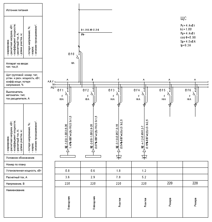
Revit also allows you to design power supply systems and load calculations in a tabular form. The disadvantage is that it is impossible to conduct calculations, select equipment and draw up schemes in accordance with the regulatory documents in force in the territory of the Russian Federation. Creating single-line diagrams is a fairly time-consuming procedure that takes a lot of time.
')
When I was working in Autocad, I used an Excel spreadsheet to calculate: put the power of the connected equipment, the name, location, type, length, and many more parameters, did the calculation, and then plotted the diagrams using the Autocad plug-in .
Now, when working with Revit, all this data can be obtained from the BIM model. For example, this plugin receives the following information:
- Switch number;
- Electrical loads;
- voltage;
- The number of poles;
- Power factor;
- cable type;
- Classification of electrical loads;
- Neutral conductor cross section;
- The length of the cable line.
The remaining information is calculated based on the parameters received and entered by the user.
The work of the plugin consists of three stages:
1) Getting the necessary data from the BIM-model and loading into the form for editing;
2) User editing parameters;
3) Creating a schema.
The plugin can be downloaded by reference .
To retrieve the parameters of electrical systems, we access the active document:
UIApplication uiapp = commandData.Application; UIDocument uidoc = uiapp.ActiveUIDocument; Application app = uiapp.Application; Document doc = doc.Document; Next, we extract the necessary parameters from the BIM model. In this example, we consider how to obtain the circuit parameters (number, power factor, cable type), as well as the cable core material from the cable line settings. The search for the required parameters is carried out by ID using the list of BuiltInParameters . This method of searching for a parameter will not depend on the localization of Revit.
// , "" ParameterValueProvider provider = new ParameterValueProvider(new ElementId((int)BuiltInParameter.RBS_ELEC_CIRCUIT_PANEL_PARAM)); FilterStringRule rule = new FilterStringRule(provider, new FilterStringEquals(), "", true); ElementParameterFilter filter = new ElementParameterFilter(rule); ICollection<Element> docCircuits = (new FilteredElementCollector(doc)) .OfCategory(BuiltInCategory.OST_ElectricalCircuit) .WherePasses(filter) .ToArray(); foreach (Element docCircuit in docCircuits) { // num = docCircuit.get_Parameter(BuiltInParameter.RBS_ELEC_CIRCUIT_NUMBER)? .Element.Name; // powerFactor = docCircuit.get_Parameter(BuiltInParameter.RBS_ELEC_POWER_FACTOR)? .AsValueString(); // cableType = docCircuit.get_Parameter(BuiltInParameter.RBS_ELEC_CIRCUIT_WIRE_TYPE_PARAM)? .AsValueString(); // Element wireType = new FilteredElementCollector(doc) .OfClass(typeof(WireType)) .FirstOrDefault<Element>( e => e.Name.Equals(cableType)); string coreMaterial = wireType.get_Parameter(BuiltInParameter.RBS_WIRE_MATERIAL_PARAM) .AsValueString(); } After obtaining the necessary parameters, you can proceed to the creation of the scheme. We create transaction and we insert elements of the scheme into the file. By the way, the units of measurement are feet, so when inserting elements you need not to forget about it.
using (Transaction tx = new Transaction(doc)) { tx.Start(" "); double xCoord = 0; // foreach (Circuit circuit in panel.circuits) { // . FamilySymbol lineSymbol = FilteredElementCollector(doc) .OfClass(typeof(FamilySymbol)) .Where(q => q.Name == "SLD_") .First() as FamilySymbol; // XYZ coords = new XYZ(xCoord, 0, 0).ToFeets(); // SLD_ FamilyInstance line = doc.Create.NewFamilyInstance(coords, lineSymbol, uidoc.ActiveView); // ParameterSet parametersLineOut = line.Parameters; // foreach (Parameter param in parametersLineOut) { switch (param.Definition.Name) { case " ": param.Set(circuit.number); break; case " ": param.Set(circuit.cableType); break; case " ": param.Set(circuit.powerFactor); break; } } xCoord = xCoord + 25; } tx.Commit(); } Everything, the scheme is ready!
Source: https://habr.com/ru/post/330128/
All Articles