Creating a 2.5D software engine
Currently, interest in software engines like those from Quake, DOOM or Duke Nukem 3D games is almost zero. However, these engines had their charm and, for example, I really like the graphics of just such engines with unrealistic textures on the walls. Of course, such textures can be applied without filtering in OpenGL, getting the same level of graphics, but still writing your own software engine was very interesting. I couldn’t write the Quake level engine at the time, because I couldn’t create a 3D map editor - I just had no idea how to draw a 3D map at all. Yes, and with a high probability, texturing in an arbitrary case in my version (without an assembler) would be very slow. But the engine level DOOM I obeyed. I wrote the basis for such an engine in 2002, using the book by Shikin and Boreskov “Computer graphics. Polygonal models ”. On the basis of that engine, using graphics from Doom, I wrote a kind of game under MS-DOS at Watcom C. Several years ago, I decided to remove the engine code from that game and rework it into my current C ++ language knowledge and ideas about how would arrange this engine. Well, at the same time move this engine under Windows and add tilts of your head, as in Blood or Duke Nukem. About what happened as a result, I wrote in this article.
So, in this article I will tell you how to write a Duke Nukem 3D level engine, however, without the inclined surfaces that are in this game. That is, to build the Build my creation did not reach. In addition, the presented engine will use not the BSP (as DOOM), but the portals method. My original engine used just BSP, but as it turned out, the portal method works faster. About BSP, I will also tell and give the engine itself using it.
In engines of the described type a flat map. This means that the labyrinth consists of zones (sectors) that cannot be located one above the other. Sector for the convenience of working with them, we will consider convex polygons.
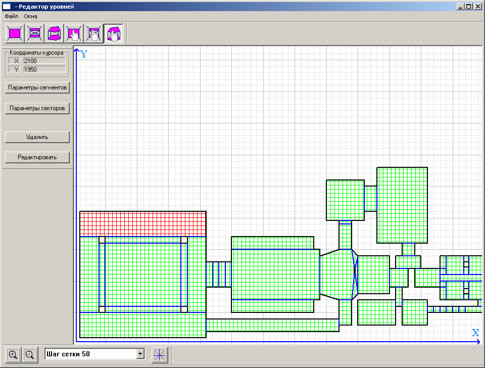
View of the maze from the map editor
')
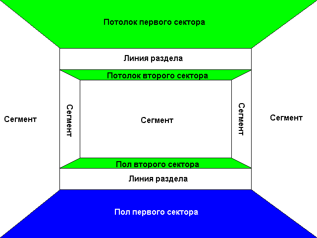
For each sector sets the height of the floor and ceiling, as well as walls (segments) that are in the sector. Such segments are a solid wall and are displayed when drawing from floor to ceiling. Between the sectors are special segments - dividing lines. The dividing lines close the elevation differences between sectors and, in addition, are portals to another sector from the selected one. It should be borne in mind that for a portal engine within a sector, the segments and dividing lines cannot be located not by a convex polygon, otherwise the ordering of segments within the sector will be required (if this is not done, it will be unclear which segment to display in the foreground and which in the back). For the BSP engine, this is not important - he himself arranges the segments at the stage of splitting the map.
How does the BSP engine work? Yes, very simple. It is enough to take any segment or dividing line of the map and cut the entire map space (tree root) into two halves, as shown in the figure - this will be the left and right subtree.

Split card
Each of these halves can also be cut by another selected line. And so on, until the moment when there will be nothing to break and you have come to a leaf of a tree (or you have achieved the required quality of splitting - DOOM, for example, breaks up, as I recall, to convex polygons, and I break to individual lines). With such a cut, due to rounding errors, the segments and dividing lines will be cut with rounding errors, so it is worth throwing out fragments with a length of the error level from the list of resulting fragments. In general, the algorithm is recursive. When drawing graphics, it is sufficient to recursively compare the position of the player relative to the breaking lines and output the maze from the sheet (where the player is) to the root in the reverse order. This will automatically get the ordering of segments and dividing lines from the player to infinity. During the processing of the tree, you can determine the visibility of subtrees, if you describe rectangles around them and check whether the player can see these rectangles or not. This technique will also accelerate the maze.
The portal engine works a little differently. First of all, it does not require a partition of space. We just need to find out which of the sectors the player is in, and having a list of sector portals, go from sector to sector through these portals. In order not to twist in a circle, it is worth blocking the portals through which we have already passed. The algorithm of such a walk is also recursive, and as a result we also obtain the ordering of sectors and segments from the player to infinity. Portals can be geometric (with the help of mathematics, we cut off pieces of the map that are visible through the portal (with all rounding errors as a gift)) and on-screen (here we adjust the left and right border of the image display area on the screen). The screen portal for the software engine is more preferable, since it is very easy to implement and works very quickly. The only incomprehensible situation is possible when a player is right on the portal. In this case, when rendering this portal, we do not change the border of the portal, otherwise one of the halves will not be drawn.
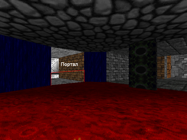
Screen portal
In order to determine whether a player is on the portal or not, we use the equation
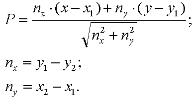
In this equation, the portal is defined by a straight line with coordinates (x1; y1) - (x2; y2), and the position of the player corresponds to the coordinates (x, y). If, as a result of the calculation, the value of P will be in a certain range (I have taken from -10 to +10), then we can assume that (x, y) is very close to the straight line on which the portal lies.
Common to both engine variants is the method of drawing vertical and horizontal surfaces. Since we have a DOOM type engine, we will not have any arbitrarily oriented surfaces - only vertical and horizontal. How to display them? Suppose, using portals or a BSP tree, we get a set of segments and dividing lines ordered from the player to infinity. To prevent the segments in the distance from covering the already displayed ones closest to the player, we will use the horizon lines. For each column of the screen (the window size in X will be set by the macro WINDOW_WIDTH) we will set two coordinates - upper and lower. So we need the TopLine array [WINDOW_WIDTH] and the BottomLine array [WINDOW_WIDTH]. Before outputting the scene, you need to initialize these arrays like this:
Where WindowHeight is the height of the window, and WindowWidth is the width of the window.
If for any column of the screen x at output it appears that TopLine [x]> BottomLine [x], then this column is completely filled, and it is not required to output it.
A segment or dividing line (which is displayed twice - as the top and as the bottom) is always cut along the horizon when output. Only the part between the horizon lines is textured. The ceiling texture is drawn between the top point of the output line or segment and TopLine [x], and the floor texture is between BottomLine [x] and the bottom point (of course, the floor is not drawn for the top dividing line, just as for the bottom the ceiling is not drawn).
When outputting a segment, we need to set the column TopLine [x]> BottomLine [x] after the output, because the segment covers everything that is behind it.

Segment output
When outputting the upper dividing line, TopLine [x] is moved to the lower point of the dividing line. When outputting the lower dividing line, the BottomLine [x] moves to the top of the dividing line.
When constructing a scene, a perspective projection is used in accordance with the formula:

Here Z is the depth coordinate (from the player), and X and Y is the position of the object relative to the player.

Before projecting, the displayed object must first be moved relative to the player’s position and turned to the angle of view:
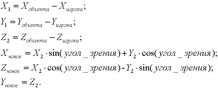
After a turn and a cut off relative to the line defining the half-plane that the player is looking at (in my case it is (-1; 1) - (1; 1)), you can perform the projection.
Texturing segments and dividing lines is done by vertical lines column by column. This uses the fact that inside the column texture points vary linearly, and 1 / Z and t / Z change linearly between the columns (the t-value of the point inside the texture). Of course, when cutting off any segments and dividing lines, it is necessary to adjust the starting and ending point of the texture both inside the columns and between the columns.
Texturing floors and ceilings is already horizontal lines. This texturing with all the math is a bit more complicated, and is described in detail in the book of Shikin and Boreskov “Computer graphics. Polygonal models ”in the chapter“ Texturing Horizontal Surfaces ”, so I was too lazy to write here the formulas for the transition between texture indices with this texturing. I would rather talk about what is not in the Shikin and Boreskov book.
To correctly fill the floor or ceiling after the withdrawal of a segment / dividing line, we need such a thing as the VisualPlanes table. The fact is that we draw the walls vertically and the floor / ceiling horizontally. Therefore, we need to first remove the wall, and then the floor or ceiling. That's what this table is for. What is she like?
Such a structure describes only a fragment of the floor (or ceiling) from MinX to MaxX with the upper and lower coordinates of the columns specified inside it. It looks simple and logical, right? It will not be so easy to understand how to move from this set of vertical columns to horizontal lines. There are two such tables - for the floor and for the ceiling. In DOOM, these floor / ceiling tables are collected and combined with each other (and this is the reason for the limit on their number in one scene). I did not do this and use the same two tables of the floor and the ceiling, and I deduce the floor and ceiling immediately after the wall is removed. Points are added to these tables by what criteria:
Here x is the coordinate of the column, y1 is the upper point of the column, y2 is the lower point of the column, WindowYCenterWithOffset is the coordinate of the center of the screen (our slider allows us to tilt our head and thus we need an offset center instead of the true center of the screen).
These tables are initialized before each wall output as follows:
But drawing on such tables is performed by the following code:
Here, DrawTextureLine draws one horizontal line of floor or ceiling texture. The output uses a buffer of initial X coordinates for each Y coordinate: long X_Table [WINDOW_HEIGHT].
First, we write MinX to the first column in this buffer. The idea here is that as we move through the columns, we track how the Y coordinate behaves. If for the left border when the floor is output, the upper coordinate decreases and the lower one increases, we note this fact in the buffer of the initial X coordinates for the given Y coordinates (X_Table [y]). But if the change in Y goes in the opposite direction, it means that we have moved to “closing” the line and need to texture the line before closing. This trick works because we use bulging sectors. By the way, when outputting a scene using a BSP tree, it should be remembered that the entire wall is displayed, while its parts can be blocked by other walls (when outputting in these places, the horizon lines are set in TopLine [x]> BottomLine [x]), and This means that with such breaks, it is required to start texturing of floors and ceilings and begin to form the VisualPlanes table again. In the method of portals there are no such problems; there the wall is always cut off along the portal.
Texturing with VisualPlanes
In my engine, you can tilt your head. This is done by shifting the coordinates of the center of the screen by an amount equal to the tangent of the angle of inclination multiplied by half the height of the screen. Of course, this gives the effect of distorting the image, so famous for the games on the Build engine.
Also in the engine there is lighting. Well, everything is quite simple here - the farther from the player (Z coordinate), the darker. For walls and floors / ceilings, the implementation of such a blackout is not difficult.
Well, it seems like everything.
The archive itself is the engine and map editor (until the end of unfinished - for example, you can not change the starting position of the player). Do not be alarmed if you see numerous shifts (>> and <<) in the source code - in some places I used calculations with a fixed point.
In the engine, the controls are cursor, mouse, ctrl-crouch, F1-F3 change of engine class (screen portal, geometric portal, BSP-tree), F5-save player coordinates, F9-restore player coordinates.
Added links to github:
Engine
Map editor
My old game like Doom under MS-DOS from 2002
So, in this article I will tell you how to write a Duke Nukem 3D level engine, however, without the inclined surfaces that are in this game. That is, to build the Build my creation did not reach. In addition, the presented engine will use not the BSP (as DOOM), but the portals method. My original engine used just BSP, but as it turned out, the portal method works faster. About BSP, I will also tell and give the engine itself using it.
In engines of the described type a flat map. This means that the labyrinth consists of zones (sectors) that cannot be located one above the other. Sector for the convenience of working with them, we will consider convex polygons.
View of the maze from the map editor
')
For each sector sets the height of the floor and ceiling, as well as walls (segments) that are in the sector. Such segments are a solid wall and are displayed when drawing from floor to ceiling. Between the sectors are special segments - dividing lines. The dividing lines close the elevation differences between sectors and, in addition, are portals to another sector from the selected one. It should be borne in mind that for a portal engine within a sector, the segments and dividing lines cannot be located not by a convex polygon, otherwise the ordering of segments within the sector will be required (if this is not done, it will be unclear which segment to display in the foreground and which in the back). For the BSP engine, this is not important - he himself arranges the segments at the stage of splitting the map.
How does the BSP engine work? Yes, very simple. It is enough to take any segment or dividing line of the map and cut the entire map space (tree root) into two halves, as shown in the figure - this will be the left and right subtree.
Split card
Each of these halves can also be cut by another selected line. And so on, until the moment when there will be nothing to break and you have come to a leaf of a tree (or you have achieved the required quality of splitting - DOOM, for example, breaks up, as I recall, to convex polygons, and I break to individual lines). With such a cut, due to rounding errors, the segments and dividing lines will be cut with rounding errors, so it is worth throwing out fragments with a length of the error level from the list of resulting fragments. In general, the algorithm is recursive. When drawing graphics, it is sufficient to recursively compare the position of the player relative to the breaking lines and output the maze from the sheet (where the player is) to the root in the reverse order. This will automatically get the ordering of segments and dividing lines from the player to infinity. During the processing of the tree, you can determine the visibility of subtrees, if you describe rectangles around them and check whether the player can see these rectangles or not. This technique will also accelerate the maze.
The portal engine works a little differently. First of all, it does not require a partition of space. We just need to find out which of the sectors the player is in, and having a list of sector portals, go from sector to sector through these portals. In order not to twist in a circle, it is worth blocking the portals through which we have already passed. The algorithm of such a walk is also recursive, and as a result we also obtain the ordering of sectors and segments from the player to infinity. Portals can be geometric (with the help of mathematics, we cut off pieces of the map that are visible through the portal (with all rounding errors as a gift)) and on-screen (here we adjust the left and right border of the image display area on the screen). The screen portal for the software engine is more preferable, since it is very easy to implement and works very quickly. The only incomprehensible situation is possible when a player is right on the portal. In this case, when rendering this portal, we do not change the border of the portal, otherwise one of the halves will not be drawn.
Screen portal
In order to determine whether a player is on the portal or not, we use the equation
In this equation, the portal is defined by a straight line with coordinates (x1; y1) - (x2; y2), and the position of the player corresponds to the coordinates (x, y). If, as a result of the calculation, the value of P will be in a certain range (I have taken from -10 to +10), then we can assume that (x, y) is very close to the straight line on which the portal lies.
Common to both engine variants is the method of drawing vertical and horizontal surfaces. Since we have a DOOM type engine, we will not have any arbitrarily oriented surfaces - only vertical and horizontal. How to display them? Suppose, using portals or a BSP tree, we get a set of segments and dividing lines ordered from the player to infinity. To prevent the segments in the distance from covering the already displayed ones closest to the player, we will use the horizon lines. For each column of the screen (the window size in X will be set by the macro WINDOW_WIDTH) we will set two coordinates - upper and lower. So we need the TopLine array [WINDOW_WIDTH] and the BottomLine array [WINDOW_WIDTH]. Before outputting the scene, you need to initialize these arrays like this:
for(n=0;n<WindowWidth;n++) { // TopLine[n]=0; BottomLine[n]=WindowHeight-1; } Where WindowHeight is the height of the window, and WindowWidth is the width of the window.
If for any column of the screen x at output it appears that TopLine [x]> BottomLine [x], then this column is completely filled, and it is not required to output it.
A segment or dividing line (which is displayed twice - as the top and as the bottom) is always cut along the horizon when output. Only the part between the horizon lines is textured. The ceiling texture is drawn between the top point of the output line or segment and TopLine [x], and the floor texture is between BottomLine [x] and the bottom point (of course, the floor is not drawn for the top dividing line, just as for the bottom the ceiling is not drawn).
When outputting a segment, we need to set the column TopLine [x]> BottomLine [x] after the output, because the segment covers everything that is behind it.
Segment output
When outputting the upper dividing line, TopLine [x] is moved to the lower point of the dividing line. When outputting the lower dividing line, the BottomLine [x] moves to the top of the dividing line.
When constructing a scene, a perspective projection is used in accordance with the formula:
Here Z is the depth coordinate (from the player), and X and Y is the position of the object relative to the player.
Before projecting, the displayed object must first be moved relative to the player’s position and turned to the angle of view:
After a turn and a cut off relative to the line defining the half-plane that the player is looking at (in my case it is (-1; 1) - (1; 1)), you can perform the projection.
Texturing segments and dividing lines is done by vertical lines column by column. This uses the fact that inside the column texture points vary linearly, and 1 / Z and t / Z change linearly between the columns (the t-value of the point inside the texture). Of course, when cutting off any segments and dividing lines, it is necessary to adjust the starting and ending point of the texture both inside the columns and between the columns.
Texturing floors and ceilings is already horizontal lines. This texturing with all the math is a bit more complicated, and is described in detail in the book of Shikin and Boreskov “Computer graphics. Polygonal models ”in the chapter“ Texturing Horizontal Surfaces ”, so I was too lazy to write here the formulas for the transition between texture indices with this texturing. I would rather talk about what is not in the Shikin and Boreskov book.
To correctly fill the floor or ceiling after the withdrawal of a segment / dividing line, we need such a thing as the VisualPlanes table. The fact is that we draw the walls vertically and the floor / ceiling horizontally. Therefore, we need to first remove the wall, and then the floor or ceiling. That's what this table is for. What is she like?
// struct SVisualPlanes { long MinX;// X long MaxX;// X long TopY[WINDOW_WIDTH];// long BottomY[WINDOW_WIDTH];// }; Such a structure describes only a fragment of the floor (or ceiling) from MinX to MaxX with the upper and lower coordinates of the columns specified inside it. It looks simple and logical, right? It will not be so easy to understand how to move from this set of vertical columns to horizontal lines. There are two such tables - for the floor and for the ceiling. In DOOM, these floor / ceiling tables are collected and combined with each other (and this is the reason for the limit on their number in one scene). I did not do this and use the same two tables of the floor and the ceiling, and I deduce the floor and ceiling immediately after the wall is removed. Points are added to these tables by what criteria:
//---------------------------------------------------------------------------------------------------- // //---------------------------------------------------------------------------------------------------- void CEngine_Base::DrawFloorLine(long x,long y1,long y2,SVisualPlanes &sVisualPlanes_Bottom) { if (y2<WindowYCenterWithOffset) return; if (y1>=WindowHeight) return; if (y1<WindowYCenterWithOffset) y1=WindowYCenterWithOffset; if (y2>=WindowHeight) y2=WindowHeight-1; if (x>sVisualPlanes_Bottom.MaxX) sVisualPlanes_Bottom.MaxX=x; if (x<sVisualPlanes_Bottom.MinX) sVisualPlanes_Bottom.MinX=x; if (y1<sVisualPlanes_Bottom.TopY[x]) sVisualPlanes_Bottom.TopY[x]=y1; if (y2>sVisualPlanes_Bottom.BottomY[x]) sVisualPlanes_Bottom.BottomY[x]=y2; } //---------------------------------------------------------------------------------------------------- // //---------------------------------------------------------------------------------------------------- void CEngine_Base::DrawFlowLine(long x,long y1,long y2,SVisualPlanes &sVisualPlanes_Top) { if (y2<0) return; if (y1>WindowYCenterWithOffset) return; if (y1<0) y1=0; if (y2>WindowYCenterWithOffset) y2=WindowYCenterWithOffset; if (x>sVisualPlanes_Top.MaxX) sVisualPlanes_Top.MaxX=x; if (x<sVisualPlanes_Top.MinX) sVisualPlanes_Top.MinX=x; if (y1<sVisualPlanes_Top.TopY[x]) sVisualPlanes_Top.TopY[x]=y1; if (y2>sVisualPlanes_Top.BottomY[x]) sVisualPlanes_Top.BottomY[x]=y2; } Here x is the coordinate of the column, y1 is the upper point of the column, y2 is the lower point of the column, WindowYCenterWithOffset is the coordinate of the center of the screen (our slider allows us to tilt our head and thus we need an offset center instead of the true center of the screen).
These tables are initialized before each wall output as follows:
SVisualPlanes sVisualPlanes_Top; SVisualPlanes sVisualPlanes_Bottom; sVisualPlanes_Top.MinX=WINDOW_WIDTH-1; sVisualPlanes_Top.MaxX=0; sVisualPlanes_Bottom.MinX=WINDOW_WIDTH-1; sVisualPlanes_Bottom.MaxX=0; for(n=0;n<WINDOW_WIDTH;n++) { sVisualPlanes_Top.TopY[n]=WINDOW_HEIGHT-1; sVisualPlanes_Top.BottomY[n]=0; sVisualPlanes_Bottom.TopY[n]=WINDOW_HEIGHT-1; sVisualPlanes_Bottom.BottomY[n]=0; } But drawing on such tables is performed by the following code:
//---------------------------------------------------------------------------------------------------- // //---------------------------------------------------------------------------------------------------- void CEngine_Base::DrawFlow(long sector_index,const SVisualPlanes &sVisualPlanes_Top) { // long level=vector_CISectorPtr[sector_index]->GetUp(); long texture=vector_CISectorPtr[sector_index]->GetCTextureFollow_Up_Ptr()->GetCurrentTexture().TextureIndex; long bright=vector_CISectorPtr[sector_index]->GetLighting(); long z=static_cast<long>((level-PlayerZ)*(WindowYCenter)); long x1; long x2; long x; long y; x1=sVisualPlanes_Top.MinX; x2=sVisualPlanes_Top.MaxX; if (x2<x1) return; long y_top=sVisualPlanes_Top.TopY[x1]; long y_bottom=sVisualPlanes_Top.BottomY[x1]; for(y=y_top;y<=y_bottom;y++) X_Table[y]=x1; for(x=x1;x<=x2;x++) { long zd; long y1=sVisualPlanes_Top.TopY[x]; long y2=sVisualPlanes_Top.BottomY[x]; if (y2<y1) continue;// ( ), // while(y1<y_top) { y_top--; X_Table[y_top]=x; } // while(y2>y_bottom) { y_bottom++; X_Table[y_bottom]=x; } // zd=(WindowYCenterWithOffset-y_top)+1; while(y_top<y1) { long dist=z/zd; long scale=dist/zd; DrawTextureLine(dist,scale,bright,texture,y_top,X_Table[y_top],x-1); y_top++; zd--; } // zd=(WindowYCenterWithOffset-y_bottom)+1; while(y_bottom>y2) { long dist=z/zd; long scale=dist/zd; DrawTextureLine(dist,scale,bright,texture,y_bottom,X_Table[y_bottom],x-1); y_bottom--; zd++; } } // top bottom long zd=(WindowYCenterWithOffset-y_top)+1; for(y=y_top;y<=y_bottom;y++,zd--) { long dist=z/zd; long scale=dist/zd; DrawTextureLine(dist,scale,bright,texture,y,X_Table[y],x2); } } //---------------------------------------------------------------------------------------------------- // //---------------------------------------------------------------------------------------------------- void CEngine_Base::DrawFloor(long sector_index,const SVisualPlanes &sVisualPlanes_Bottom) { // long level=vector_CISectorPtr[sector_index]->GetDown(); long texture=vector_CISectorPtr[sector_index]->GetCTextureFollow_Down_Ptr()->GetCurrentTexture().TextureIndex; long bright=vector_CISectorPtr[sector_index]->GetLighting(); long z=static_cast<long>((PlayerZ-level)*(WindowYCenter)); long x1; long x2; long x; long y; x1=sVisualPlanes_Bottom.MinX; x2=sVisualPlanes_Bottom.MaxX; if (x2<x1) return; long y_top=sVisualPlanes_Bottom.TopY[x1]; long y_bottom=sVisualPlanes_Bottom.BottomY[x1]; for(y=y_top;y<=y_bottom;y++) X_Table[y]=x1; for(x=x1;x<=x2;x++) { long zd; long y1=sVisualPlanes_Bottom.TopY[x]; long y2=sVisualPlanes_Bottom.BottomY[x]; if (y2<y1) continue;// ( ), // while(y1<y_top) { y_top--; X_Table[y_top]=x; } // while(y2>y_bottom) { y_bottom++; X_Table[y_bottom]=x; } // zd=(y_top-WindowYCenterWithOffset)+1; while(y_top<y1) { long dist=z/zd; long scale=dist/zd; DrawTextureLine(dist,scale,bright,texture,y_top,X_Table[y_top],x-1); y_top++; zd++; } // zd=(y_bottom-WindowYCenterWithOffset)+1; while(y_bottom>y2) { long dist=z/zd; long scale=dist/zd; DrawTextureLine(dist,scale,bright,texture,y_bottom,X_Table[y_bottom],x-1); y_bottom--; zd--; } } // top bottom long zd=(y_top-WindowYCenterWithOffset)+1; for(y=y_top;y<=y_bottom;y++,zd++) { long dist=z/zd; long scale=dist/zd; DrawTextureLine(dist,scale,bright,texture,y,X_Table[y],x2); } } Here, DrawTextureLine draws one horizontal line of floor or ceiling texture. The output uses a buffer of initial X coordinates for each Y coordinate: long X_Table [WINDOW_HEIGHT].
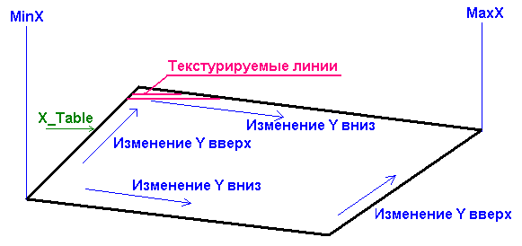
First, we write MinX to the first column in this buffer. The idea here is that as we move through the columns, we track how the Y coordinate behaves. If for the left border when the floor is output, the upper coordinate decreases and the lower one increases, we note this fact in the buffer of the initial X coordinates for the given Y coordinates (X_Table [y]). But if the change in Y goes in the opposite direction, it means that we have moved to “closing” the line and need to texture the line before closing. This trick works because we use bulging sectors. By the way, when outputting a scene using a BSP tree, it should be remembered that the entire wall is displayed, while its parts can be blocked by other walls (when outputting in these places, the horizon lines are set in TopLine [x]> BottomLine [x]), and This means that with such breaks, it is required to start texturing of floors and ceilings and begin to form the VisualPlanes table again. In the method of portals there are no such problems; there the wall is always cut off along the portal.
Texturing with VisualPlanes
In my engine, you can tilt your head. This is done by shifting the coordinates of the center of the screen by an amount equal to the tangent of the angle of inclination multiplied by half the height of the screen. Of course, this gives the effect of distorting the image, so famous for the games on the Build engine.
Also in the engine there is lighting. Well, everything is quite simple here - the farther from the player (Z coordinate), the darker. For walls and floors / ceilings, the implementation of such a blackout is not difficult.
Well, it seems like everything.
The archive itself is the engine and map editor (until the end of unfinished - for example, you can not change the starting position of the player). Do not be alarmed if you see numerous shifts (>> and <<) in the source code - in some places I used calculations with a fixed point.
In the engine, the controls are cursor, mouse, ctrl-crouch, F1-F3 change of engine class (screen portal, geometric portal, BSP-tree), F5-save player coordinates, F9-restore player coordinates.
Added links to github:
Engine
Map editor
My old game like Doom under MS-DOS from 2002
Source: https://habr.com/ru/post/329972/
All Articles