Client application architecture (structuring mechanisms)
First story
Some time ago I worked in a gaming company, which was led by a German. Making games was not the main business of this German. The main income he received from the sale of cosmetics and from the delivery of commercial real estate for rent. Having a gaming company was a way to stand out among their familiar businessmen.
German game company developed 3 types of games:
- Flash games for mobile phones with support for J2ME technology.
- Educational games for the Nintendo DS handheld game console. The customers for these games were European publishers, and the buyers were parents whose children had problems learning in math, English or German. The games division for Nintendo DS has released a lot of games. Although they did not become AAA-titles, they paid for their development and brought a small profit.
- Games for the Nintendo Wii platform.
In the last team was me. The team had to develop a game for little girls on the children's brand. The brand was quite famous in Germany (it was the main market) and in several other European countries: in France and in the UK.
')
From the very beginning, only the general outline of the game was clear. The little fairy walks in the garden, meets her friends (other fairies), talks to them and invites you to a party. Preparation for this party takes up a significant part of the game: the fairy decorates the garden, collects apples, cooks a festive cake from them. The party is fun: the fairy and her friends play musical instruments and then dance.
It was assumed that the game will be a sequence of mini-games. Each mini-game is dedicated to a specific theme: decorating the garden, picking apples, cooking a festive cake, playing music and dancing. Despite the fact that the themes of mini-games were clear, their details were not clear. There was no game designer in the team.
At first, two programmers and one 3D modeler worked on the game. When I joined the team, there was no elaborated game design (or the person responsible for it), nor a platform on which to make the game.
On the second day after my employment, the owner of the company approached me and asked: “When will the game be ready?”. By that time I had experience in the gaming industry and, according to this experience, the development of such a simple game by a team of 3-4 people took about a year. So I said that it would take about a year.
To this the German answered me: “There is no such term. The game must be done after 3 months. ” A little bit fucking, I asked: “Why in three months?” To which the German answered me: “I will have a birthday, and it is necessary that the game be made for my birthday”.
For such a hard time requirement there were also objective prerequisites. The German had a contract with the publisher, according to which he received a fixed amount of money for development plus a percentage of sales. But the percentage of sales he received only if the game will be delivered on time. And the deadline for the game coincided with his birthday.
After the 4th programmer was added to the team, the question of choosing the bosses was on the agenda. How do they usually form a project team? According to the correct approach, the leader is first sought, and then he hires the rest of the staff. Here, the opposite was done. At first, employees were found, and then the authorities began to see which of them could be the leader. It would be okay if, when choosing a manager, professional skills were put at the forefront.
But as the leader, they chose a person who promised to make the game in 3 months.
After the appointment of the team leader, work began on the game. Problems with game design and lack of technology have not been resolved. Therefore, the work did not move. This pretty angered the newly appointed manager. Frequent dialogue between him and the programmer:
Leader: “Where is the game about apples?”
Programmer: “Not done yet”.
Leader: “When will it be done?”
Programmer: “I do not know. I don’t understand what to program. ”
Leader: “Well, you are a programmer! Think up! ”
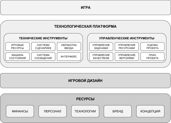
The game development system in the game studio can be represented as a hierarchy of 4 system levels.
The first system level is the resource level. These include: finance, employees (who are available either in the market, or within the company), brand (if the game is created by brand), the original concept of the game. This level sets the foundation for the entire project.
The second system level is game design. It should not represent “game design in a vacuum”. On the contrary, it must rely on available resources.
For example, the budget of the mentioned game for girls was insignificant. In addition, only half of the amount could be spent on development, since the second half was intended for the purchase of equipment (computers, televisions, devices, testkits) and the licensing of programs for artists and programmers. A small development budget and platform limitations made it impossible to use realistic graphics and realistic physics in the game. There was no money to purchase a license for a technologically advanced engine, and the game console did not allow the use of shaders. Had to use what is already there - NintendoWare's free NintendoWare 3D engine.
The use of the physical engine gives the player freedom of movement. A player can move along the game level in any direction until he collides with an obstacle. But the support of physics requires certain costs from both designers, who must arrange collision boxes on the stage, and programmers who have to handle collisions. All this affects the duration of the development. Therefore, we decided to limit the use of physics in only one, the main stage and implement mini-games exclusively using animations.
The third system level is a technology platform. The platform allows you to create games for existing game design, or rather, certain types of games. To achieve this goal, it uses available resources of the first system level.
The platform includes certain technical and managerial tools. The technical tools are:
- game resource management system;
- game state machine, or game flow control system (game flow);
- scripting system;
- messaging and messaging system;
- input processing system (for example, in the case of a Nintendo Wii game console, it can recognize the movements of the Wii Remote controller);
- user interface;
- asset loading system (surface, static and dynamic objects, scripts);
- system of loading and saving user data;
- etc.
Management tools include:
- task management system;
- quality management system;
- resource management system;
- version control system;
- project evaluation;
- project plan;
- etc.
The fourth system level is the game itself or a series of similar games.
Partitioning into system levels allows you to struggle with complexity. There is a difference whether a programmer makes a mini-game on a specific design and using a specific platform, on which he can ask questions to other experienced programmers working in the same company, or “pour code” on a low-level API. The complexity of the implementation of the same mini-game in both cases will be unequal.
For example, after the game design of each mini-game was invented and described and a platform was implemented, one programmer could implement one mini-game in draft quality in 3 working days. Another 2 days were required in order to add multiplayer to the mini-game and bring some beauty to it. Thus, the creation of one mini-game in the final quality cost 5 man-days. Meanwhile, as before this moment (with the missing design and technological platform) weeks passed, and the work did not move.
Second story
Once I was invited for an interview in one startup. The project was not very interesting for me, but it was bribed by the fact that the company was literally five minutes away from my house. I thought that for the first time in my career I could not waste time traveling to work.
The start-up interview was conducted via Skype, and the questions were quite adequate. Basically, they related to my previous experience. What did I do? What did you do? What tasks faced?
The procedure for selecting candidates for a startup was a two-step. I passed the interview successfully, so after a while the head of the startup contacted me and offered to perform the test task.
The test task sounded like this:
Develop a text-based online editor like the one used in Google Docs.
It was necessary to support the following features:
- splitting the text into paragraphs;
- automatic text distribution among pages;
- text formatting;
- possibility of simultaneous editing by several users;
- display and marking of all changes made by different users;
- document storage in the “cloud”.
To perform the test task stood week.
Needless to say, I did not do this test task, but, politely thanking the manager, I did not get in touch with him.
Subtotals
Summing up, it can be argued that in both stories the same mistake was made - the omission of the system level [6].
In the first story, when working on a game for girls, the “game design level” and “technology platform level” were missed, which led to a stalled work on the project and increased development time. Work on the project was unlocked only after the missing levels were added: the game design was worked out and the platform was implemented (albeit a lightweight one).
In the second story, system levels are also missing. The proposed task is clearly more complicated than the usual test task. To combat the complexity, the solution should be presented in the form of a hierarchical system, where the lower layers ensure the operation of the layers above. But such work requires considerable effort and imposes excessive demands on the qualifications of an engineer. He should understand literally in all areas: in network protocols, in text editors. Therefore, it is more accessible for the company than for one person.
System Level Hierarchy
The system level detection approach can be used when designing applications. Of course, if we are talking about writing some simple program, then there is no need to split into levels. A multi-level (or multi-layered) architecture makes sense if a complex application or an application of medium complexity is developed.
Identifying system levels is the first step to developing an architecture. If you read a book on object-oriented analysis and design, you probably have often seen how the author asks the question: “How to find candidates for classes?”. Perhaps programming, you yourself asked yourself the same question.
The process of structuring an application should not begin with identifying classes. A class is too small an element of abstraction. If you draw an analogy with the construction, the class - as a separate brick. And the construction of a skyscraper is unlikely to begin with the question of how to lay it out of bricks.
Three-layer architecture
Fowler [7] and Microsoft’s application architecture guide [5] distinguish three system levels (in other words, three layers of abstraction) into which the developed application can be divided.

Note: The original version of the chart can be viewed on the Microsoft website.
The first layer of abstraction is the data access layer. The tasks of this layer include abstraction from the database. SQL queries to the database in which the application data is stored are hidden behind the facade that the business layer uses.
The second layer of abstraction is a layer of business logic. It contains domain objects as well as functions for working with them. These functions implement this business logic.
The third layer of abstraction is the user interaction layer. This layer includes user interface components.
The three-layer architecture described in the Microsoft manual is working. The only thing that causes me to be misunderstanding is some thing related to the interaction of the business logic layer with the data access layer.
According to my understanding, domain classes should be related to the business logic layer. On the other hand, the main task of the data access layer is to get data from the database and copy this data to business objects.
It turns out a contradiction:
- On the one hand, business objects should be declared at the level of business logic, since logically relate to it.
- On the other hand, business objects must be accessible at the data access level so that data read from the database can be copied into them.
Seeing this contradiction, I would like to offer a slightly different approach to partitioning the application into system levels.
Five-tier architecture
The approach I propose involves splitting the client application into 5 system levels. The key of the proposed five levels are only two. This means that the client application, at a minimum, can consist of two system levels. Using all 5 layers is an optional and possibly more desirable option.
Restrictions
The proposed architecture has several limitations:
First, it was tested by me and colleagues when creating 5 clean client applications. Those. there was no server component, the database was not used, and applications were launched on desktop computers and mobile devices .
Four applications are designed to create and edit various game resources. The fifth application is a service program designed to provide services.
Secondly, the developed applications were designed to create and edit documents. They had minimal business logic (for example, they should not have to pay), but a rich interface — it contained many different controls (controls) for creating and editing data (track editors, function graphics, property editors, etc.).
Description

The first level can be called infrastructural. It is called so because it contains the infrastructure, i.e. libraries, modules, classes and methods that are used throughout the application.
If application development is conducted in the C ++ programming language, then, as a rule, the infrastructure level includes:
- libraries work with raster images;
- XML and JSON parsers;
- compression and data encryption libraries;
- libraries of containers and various auxiliary classes (STL, boost);
- helper utilities written by application developers.
The infrastructure level is a “dump” of various useful utilities and auxiliary classes. The presence of such a layer allows you to get rid of entropy in the higher layers. Everything that is useful, but difficult to order, needs to be placed in the infrastructure level.
The second level can be called a data model. This level is key, because at least one client application can hardly do without it.
The name “data model” echoes the name “data access layer” from Microsoft's application design guide. Despite the fact that the tasks of this level approximately coincide with the tasks of the data access layer, there is also a significant difference:
The data model is combined with a data source , which uses files in XML or JSON formats. Data storage is not used by the DBMS.
The data model is an object model of the domain [7, p. 140] and consists of self-serializable classes whose objects load themselves from a file and save themselves to a file.
The data model contains business objects, which, according to the mentioned guidelines, should be included in the business logic layer.
These objects either do not contain any logic, or have some minimal logic associated, for example, with data verification. The number of methods possessed by these objects is also small. As a rule, they either provide simplified access to other objects associated with the first, or are responsible for the serialization and deserialization of the object itself.
According to Fowler [7, p. 140] the domain object model refers to business logic. Therefore, making a direct comparison of the proposed five-level model with the classical three-layer architecture [5], it is difficult to relate to which layer of abstraction the data model corresponds to. It turns out some mix between the data source, the data access layer and part of the business logic. It is justified when there is no need to spread across physical layers (tires) data storage (DBMS) and their processing (application server).
In the visual effects program and in the program for creating animated blueprints, data model objects themselves serialize themselves to XML. These are self-retaining objects. The data model includes both in-memory objects as instances of classes, as well as serialized XML files on the hard disk.
In the GPS navigator, the data model is a bit more complicated. It consists of several specialized databases and a code layer that provides access to the data.
Combining the object model of the domain, the data access layer and data sources in one system level allows you to use the “design based on the domain” approach and create a single solution space that is used to organize data both within the application and during its storage.
Such an approach can be applied if the application does not need to operate with a large array of data and / or use a DBMS. Otherwise, the level of the data model will still have to be divided.

Drawing “Comparison of the classic three-layer and five-tier architectures”
The third level is the level of services or services. From my point of view, this particular layer corresponds to the layer of business logic from the Microsoft management. However, such a correspondence is formal, because in the case of editing programs it is difficult to understand what is business logic. If the user just needs to create and / or edit a document (for example, a visual effect or animated blueprint), then what should be considered business logic? The editing process itself? There are no financial postings and no process control system in the editing applications. To the business logic could be attributed to the object model of the domain. But it is already located at the data model level.
Such questions indicate that the mechanical mapping of the three-layer architecture outlined in the Microsoft manual and the five-tier architecture proposed in this article is not well beyond consideration of specific application architectures.
The service level is a set of functional modules. Each module is responsible for implementing any single operation performed on the data model.
In some client applications, there may be many such business functions. In some - a little. And in some - they are completely absent. Therefore, for a number of applications, the service level can be skipped.
For example, in a visual effects editor, each effect can be saved in XML format. However, in order for this visual effect to be used in the game, it needs to be converted to a binary format. This conversion is done by the compiler. This compiler is a separate service.
In the GPS-navigator services more. Because this application is designed to provide services to users. These services include:
- drawing a map of the area where the user is located;
- laying a route to a given point;
- route navigation;
- search for coordinates by address.
The modules responsible for the provision of services are located at the service level. Services do not depend or weakly depend on each other. They can be placed in different modules and avoid unnecessary connectivity between them.
The fourth level is responsible for editing. This level is typical for program editors. It contains generic components or generic editors. First of all, I mean:
- Document / View Architecture (also known from the MFC Class Library) [1]
- Undo / Redo Management [3]
The Document / View architecture binds a specific file extension to a specific document type, and also binds a specific document type to a specific view responsible for its visualization.
Undo / Redo Management provides support for undo operations. Thanks to this possibility, the user, while editing a complex document, can cancel an erroneously performed operation at any time. As a result, editing becomes resistant to errors and not scary for a person. Such functionality has become the de facto standard of various editing programs.
The editing layer is part of the presentation layer of the classical three-layer architecture [5]. Its selection in a separate layer due to the fact that it sets the frame for editing . In addition, the architectural concepts used to organize the editing level are independent of the data visualization .
Level five is also key. No client application can do without it. This level contains components responsible for data visualization and user interaction.
Despite the fact that this level is called in the same way as the layer from the classical three-layer model, however, it has slightly less responsibilities. The exclusion from it of the components responsible for editing allows the developer to concentrate his attention on data visualization and writing various controls .
The separation between the level of editing and the level of representation may be mental rather than physical. The components of both layers can be located in one module.
Connection with the design pattern “Model - View - Controller”
The concept of “Model - View - Controller” was formulated by the Norwegian Trygve Reenskaug in 1978/79 during his work in the Xerox PARC laboratory [8]. It involves the division of the structure of the application into three components:
- Model. Describes the data. Not involved in data conversion. Does not contain code for their visualization.
- View. Responsible for visualizing the Model.
- Controller. Changes the Model, usually as a result of user actions.
One of the most ambiguous components is the controller . In different implementations of the “Model - View - Controller” design pattern , the Controller component performs different duties. For example, the Mac OS and iOS operating system APIs have a view controller that is responsible for managing views, and the Microsoft Foundation Classes class library for programming under Windows uses the Document-View architecture, in which Model is understood as a Document , and the Controller is absent .
In a number of interpretations, the Controller understands the processing of commands from input devices (for example, mouse and keyboard). In other cases, visual input elements that are displayed on the screen (for example, a menu) [8] are added to input devices.
Some interpretations identify the controller with the business logic of the application [8].
Although the concept of “Model - View - Controller” and does not have an established view of the element Controller , however, it involves the separation of data from their visualization.
In this regard, we can say that the three-layer architecture described in the Microsoft manual [5] and the five-level architecture described in this article to some extent correspond to the concept of “Model - View - Controller” . The criteria used to divide the application into system levels, overlap with the criteria used in the “Model - View - Controller” to highlight its components.
The organization of selected elements in the form of layers unambiguously asks their hierarchy and eliminates various questions on the topic “Should the Controller be aware of the View?” Or “Should the Model update the View when it changes?” .
The separation of architecture into layers sets not only the logic of the selection of components, but also clearly specifies the dependencies between them. The data model knows nothing about the level of services or the level of editing. However, it can be transformed by them. The service level knows nothing about the model visualization. However, the presentation layer uses both the model and the services.
Also in the proposed architecture there is no such ambiguous component as the Controller.. Instead, the services level, the editing level and the presentation level are added, whose responsibilities and position in the hierarchy are clearly specified.
At the editing level, the “Document - View” architecture is used , which is a subtype of the “Model - View - Controller” design pattern . This architecture involves the allocation of classes Document (responsible for storing and transforming data and, in fact, is a wrapper on classes from the data model) and View (responsible for visualizing data and processing commands from the user).
Using Document-View Architecture allows you to specify the interaction between the model and the view (view), add the ability to edit the data model and support the ability to cancel operations.
Example 1. All Sparks Editor
Overview
All Sparks Editor is an application for creating visual effects. In appearance, this application resembles an audio editor. There is a rationale for this: just like sound, a visual effect has a certain duration. Therefore, the visual effect editing window contains a timeline located horizontally. Under the time axis are tracks that are also horizontally oriented. User can add and delete tracks.

The main window of the editor All Sparks
On the tracks are placed components. The user can select these components from the Component List and drag them to the tracks.
The components are:
- particles;
- billboards;
- three-dimensional models;
- sources of light;
- music and sounds;
- various forces, for example:
- force of force;
- air resistance force;
- turbulence force;
- etc.
The force components act on the particle components. If the “particle” component is placed on one track, and the “force of the force” component is positioned under it, then during the playback of the effect, the force of gravity will act on the flying particles. Gradually, the particles will fall down.

Components are located on the tracks.
Each component is represented as a rectangle. Since a component can occupy space only on one track, the height of the component coincides with the height of the track. The length of the component determines the duration of its existence, and the beginning - the time of its appearance when the effect is played.
In order for the user to quickly identify the type of component, each component type has its own color.
After placing the component on the track, the user can set various of its properties. Component properties are displayed in the property editor, which is located at the bottom of the editing window.

Property
Editor The property editor is a two-column table with multiple rows. In the left column indicates the name of the property, and in the right - the values.
The user can look at how the visual effect looks like in the preview window. This window is located on the left side of the main program window. In order to reproduce the effect, the user must press the Play button. After that, the effect is compiled into a binary format and transferred to the game engine for playback.

Visual effect in the preview window
Architecture
The architecture of the editor of visual effects can be represented as a hierarchy of 5 system levels:

The first system level is infrastructure. It is a set of auxiliary classes. As a rule, these classes contain some mathematical methods that are absent in the standard Math class, or some additional operations with strings and file names. Infrastructure level is very small.
The second system level is the data model. The data model describes the structure of the visual effect: tracks, components on them, properties of components.

Each data model class has Load and Save methods that are designed to load and save an object from / to XML. LINQ to XML is used to read and write XML.
public class Component { public Dictionary<Guid, Property> Properties { get; } = new Dictionary<Guid, Property>(); public Component Load(XElement item) { if (item == null) { throw new ArgumentNullException(nameof(item)); } // Loading logic return this; } public XElement Save() { return new XElement("component", Properties.Values.Select(prop => prop.Save()).ToArray() ); } } The third system level is the level of services and services. Currently this layer contains only one service. This is a compiler. The compiler converts the effect into a binary format, which can then be used by the engine.
Some time ago, the visual effects editor was not integrated with the game engine. These were two different applications. And in order for the visual effect to be seen how it looks, there was another service that allowed data to be exchanged between the client program (visual effects editor) and the server, which was played by the viewing program. This service was called a communicator.
Thus, previously there were two services. And now, since the integration of the visual effects editor with the game engine has taken place, the need for a communicator has disappeared, and there is only one service left - the compiler.
The fourth system level is the edit level. It implements two architectures:
- Document / View architecture, which allows you to open visual effects files in the original format and create different views for editing and displaying them.
- Undo / Redo Management, which is a stack of commands that can be executed or canceled when editing an effect.
The fifth system level is the level of user interaction , which contains various controls. In our case, such controls are the timeline, tracks, property editor, etc.
Example 2. Genome editor
Overview
The second application, the architecture of which I would like to consider, is the editor of animated blueprints. Blueprint is a software module that implements a specific functionality, but not written in a programming language, but presented as a graph. It turns out that the blueprint editor is a visual programming tool.
For the first time, blueprints were implemented in the Unreal Engine 4 [2]. They are used for various purposes, including for “programming” the logic of the game scene or the behavior of the character.
In modern video games to create high-quality images of 3D-animators have to do a lot of different animations. If we are talking about creating a humanoid character, then you need to animate a lot of movements: walking, running, jumping, squatting, raising hands (together and each hand separately), etc.
Often, a character’s behavior cannot be reduced to playing one of the animations or playing a predetermined sequence of these animations. Sometimes animations need to be combined. For example, a character may walk while carrying a cup of hot coffee in his right hand. Without stopping, he can bring this cup to his mouth to take a sip.
Modern 3D engines allow you to mix different character animations, i.e. play them at the same time. This is required for a smooth transition from one animation to another, or when one animation plays on one part of the character's skeleton, and the other on the other. In order to define the logic of such a mixture, the editor of animated blueprints is used. It first appeared in the Unreal Engine 4. And since it seemed convenient to our 3D animators, it was necessary to create a similar editor with us.

The main window of the editor Genome
An animated blueprint is a graph. It consists of nodes and connecting lines. Lines can be drawn not to an arbitrary location on a node, but to a specific socket. Each node of the graph may contain one or more sockets.
Nodes represent various operations, for example, comparison, addition, subtraction, cycle, branching, etc.

Examples of operation nodes
There are more complex nodes such as state machine. Complex nodes contain nested graphs. For example, a state machine contains a state graph, each node of which represents a certain state, and connecting lines - conditional transitions. States also contain nested graphs.

State machine
To hit the nested graph, the user must double-click the node with the mouse. The nested graph can be edited in the same way as the parent graph. It also consists of nodes and connecting lines.
Each node can have one or more sockets. Sockets are located on the left and right sides of the node. The sockets on the left are called input, and those on the right are called output. Input data or control signals are sent to input sockets, and the output of the operation for which the node is responsible can be obtained from output sockets.

Nodes with different input and output sockets
Sockets are typed, as are the connecting lines between them. There are sockets for integers and real numbers, for Boolean values and strings. Typing sockets allows you to avoid errors when an output socket of one type is connected to an input socket of another type, for example, a string with an integer. Directly such a connection is impossible, only through an auxiliary node that performs the type conversion operation.
Trunks between sockets define data flows and control flows. To organize control flows, there are specialized sockets, which are called animation pose in the animation graph, and exec in the event graph.
More information about blueprints, nodes and sockets can be found in Blueprints Visual Scripting from the Unreal Engine 4 Documentation [2] manual. A similar approach was used in the Genome editor.
Architecture
The architecture of the animation blueprint editor can be represented by a hierarchy of 5 system levels. This hierarchy is similar to the one used in the visual effects editor. The names of the levels, their purpose, the individual components almost coincide. But there are differences to which I want to draw your attention.
The differences are due to the fact that the graph editor is the basis for the animation of blueprints. The task was to reuse this editor when rewriting other applications: the material editor and the dialog editor.
This means that one cannot restrict one data model, which will represent the graphs for animated blueprints. We need some basic data model for all possible graphs. And you need some framework for creating and editing graphs. This framework should be used by specific editors: editor of animated blueprints, dialog editor, editor of materials, etc.

The infrastructural level of the animation editor of blueprints is almost the same as that of the visual effects editor with one exception. Since the control for graph visualization is implemented using the WPF technology, the infrastructure layer contains all sorts of auxiliary classes that facilitate the work with WPF, as well as the styles for the controls used. Styles are applied not only in the Genome editor, but also in other applications. Therefore, they are located at the infrastructure level.
The data model is divided into two parts. The first part is the generalized data model for any graph and any blueprint. It is a hierarchical graph. The graph contains nodes and connecting lines. Some nodes may contain other graphs.

The second part is the data model for animated blueprints. It contains classes that describe the animation blueprint nodes. Such nodes include mathematical operations, comparison operations, type conversion operations, animation mixing operations, etc. Separate classes represent sockets and connecting lines.

On top of the data model is the level of services . As in the case of the visual effects editor, this level contains only one service - the compiler. The compiler converts the animated blueprint in the original format into a binary format that is reproduced by the engine.
The editing level is divided into three parts. The first part is the library that contains the base classes for the Document / View architecture and for managing Undo / Redo. This library is used both in the animation blueprint editor and in the visual effects editor.
The second library is responsible for editing graphs. It allows the user to create nodes, arrange them in the editing window, connect nodes with connectors of various types, as well as delete nodes and switch between nested graphs. However, this library deals with a generalized graph model and does not know anything about specific nodes for the editor of animated blueprints.
The third library is intended for editing animated blueprints. It allows you to create, delete, edit specific animation blueprint nodes.
The level of user interaction is also divided into three parts. The first part contains the basic components of the user interface. The second part contains the interface components used to edit graphs. And the third part contains user interface components used to edit animated blueprints.
In general, the architectures of the visual effects editor and the animation blueprint editor are very similar and consist of the same system levels. However, there are also differences that are caused by the need to create a generalized library for editing graphs. These differences translate into the fact that, first of all, the data model is divided into two parts:
- generalized data model that describes a generalized graph;
- and a specific data model that describes a graph of a particular type — an animated blueprint.
Together with the data model, the same separation occurs at the editing level and at the user interaction level.
Example 3. GPS-navigator
Overview
In the third example, I would like to consider creating a GPS navigation application for a smartphone. This program differs from those considered in the previous two examples of applications: the editor of visual effects and the editor of animation blueprints.
The main difference is that editors are focused on creating and editing documents, while the GPS navigator is designed to provide services.
These services include:
- Help the user in orientation to the terrain. This service is performed by drawing a map of the area and specifying the place where the user is located. When the user moves, the direction of this movement is also shown.
- Building a route to a given point. Destination can be set by specifying a point on the map, and by using the search.
- Search for a specific address or place of intersection of two roads.
- Search for the nearest points of interest: cafes, gas stations, ATMs, etc.
Despite the focus of the navigation system on the provision of services, however, it also allows you to create and edit some simple documents. These include:
- user profile;
- search history of points of interest and addresses;
- edit the list of favorites (home address, address of the workplace and others).
Architecture
The architecture of a GPS navigator can be represented by a hierarchy of 5 system levels already known to us.

The first, lowest, infrastructural layer consists of libraries and utilities that are used throughout the application. Since the navigation system was developed using the C and C ++ programming languages, these libraries included:
- the stlport library, which contains a set of standard containers and algorithms and is built for different platforms;
- zlib library, which allows you to compress and decompress data using the deflate algorithm;
- libpng and libjpeg libraries for working with raster graphics in png and jpeg formats;
- aes library for encrypting data and creating electronic signatures;
- expat xml parser library for reading and parsing xml files.
The data model level is the most difficult compared to the similar levels in other considered applications. The fact is that the speed of many navigation algorithms is determined by the speed of access to the necessary data. Therefore, the data must be organized in such a way that the access speed is high.
The data contains cartographic information, which is then used to draw maps, plan a route, and search for coordinates by address.
The data model level can be divided into two sublevels:
- database;
- data access layer.
The database contains navigation data: maps, postal codes, points of interest, travel history, a list of places-favorites.
The data access layer receives data from the database and provides it to the higher level in the form of corresponding data structures.
Initially, maps in the original format are fed to the input of the compiler, which converts them into an intermediate format. As a rule, the source format is GDF 3.0. This is a text file with a specific markup. Often, a single map presented in GDF 3.0 weighs more than one gigabyte. To present the UK road network, you need 7 such maps. The intermediate format is a binary format that allows you to present complete information in a compact form.
Then the cards in the intermediate format are fed to the input of five compilers, which convert them into specialized databases.
The first specialized database contains information necessary for drawing a map. It includes not only roads, but also various areas such as parks, ponds, and forests. The main requirement for it - quick access to all elements that are in a given area.
The second specialized database stores the information necessary to build a route. Unlike the drawing database, it only contains information about the road. To build a route, you do not need to know anything about water bodies, forests, parks and the geometry of road elements. It requires only the length of the road element, the maximum speed and direction of movement. The main requirement for it is a quick access to the neighboring road elements.
The third specialized database contains addresses. The main requirement for it is a quick search for the address by the entered text and the road element by address.
The fourth specialized database contains information about postal codes. The main requirement for it is a quick search for the coordinates of the area by zip code.
The fifth database contains information about various points of interest (restaurants, cafes, gas stations, ATMs, etc.). The main requirement for it is to quickly find points of interest within a certain area.
To access map data, a data access layer is used.
Thus, the data model for the GPS navigator includes:
- maps in the original (text) format;
- compiler for converting maps from text format to intermediate binary;
- five specialized compilers that form specialized databases:
- database for drawing maps;
- database to build a route;
- database for finding coordinates by address;
- zip code database;
- database of points of interest;
- data access layer, which provides access to data from specialized databases.
On top of the data model is the level of services . Since the GPS-navigator is a service-oriented application, this level includes several function-oriented modules. Each module is responsible for any one key function or a group of similar key functions of the navigation system.
We can distinguish the following modules:
- Rasterizer card. Generates a two-dimensional or three-dimensional representation of the map in a given area.
- Module routing. Responsible for laying a route from the current location to a given point.
- Address search module. Responsible for finding coordinates by address.
- Index Search Module. Responsible for finding coordinates by zip code.
- Module search points of interest. Responsible for finding points of interest within a given area.
- Navigator. Responsible for the formation and issuance of navigation instructions when driving on a route.
The editing level is quite small and does not contain too much code. The reason for this is that the navigation system is designed to provide user services and is not intended to create or edit any documents.
There are 3 main functions that can be delegated to the editing level:
- work with user profiles (the navigation system may have several users, and the data of each user must be stored in a separate profile);
- create and manage a list of places-favorites;
- saving travel history (in the simplest case - saving destinations).
In principle, the GPS navigator can safely do without an editing layer. But if you want to support the profiles, then work with them can be delegated to this layer.
The user interaction level is responsible for presenting information for the user on the screen or on the sound card of the device, as well as for processing input from the user. It contains various screens and controls. The level of user interaction can support skins, if there is a need to make the interface comfortable when working on different devices.
Results
Let us summarize the consideration of the architecture of the three applications.
- The architecture of the client application can be represented by a hierarchy of five system levels:
- The infrastructure layer contains libraries that are used throughout the application.
- The data model level contains classes that describe the subject area.
- The service level provides services for the user. Such services include: compilation, routing, search for coordinates by address, etc. Each service is placed in a separate module, which is called a service.
- The editing level is designed to create and edit documents. It also supports the ability to cancel the operation.
- , — . .
- , . .
- , , . , , . , , , .
- . XML . . , . -, .
- , (, ), ( ). : .
Literature
- Document/View Architecture
- Blueprint Visual Scripting/Unreal Engine 4 Documentation
- Introduction to Undo Architecture
- Gregory, Jason. Game Engine Architecture
- Microsoft , 2-
- .., ..
- , . . – . from English – .: «», 2006. – 544 .: .
- @cobiot. MVC. , ,
- @cobiot. MVC.
.
Source: https://habr.com/ru/post/329032/
All Articles