Using OpenGL light sources to create color shadows
As you know, OpenGL version 1 allows using at least eight standard light sources. Using these sources you can simply build high-quality color lighting without the use of maps of illumination. As it turned out, when developing self-made simplest three-dimensional engines, for their authors this possibility does not seem obvious and therefore is ignored by them. The method described below is not suitable for moving in light sources, but it is great if the other parameters of the light source change over time (for example, the color of the light source changes, or it blinks). How to build high-quality lighting using standard OpenGL lighting sources will be discussed in the article.
I must say that this article has been planned for a very long time - years since 2004, when a three-dimensional engine was written using the described method. However, the abundance of formulas and laziness made me soon abandon the writing of the article. The last time I touched the text in 2008. On this date, the article stopped and I did not plan to revive it. But recently, in the topic about the source code for Quake 2 , I was still asked to tell about the technology used to build a picture used in my three-dimensional engine. The relevance of such late articles for modern programming of three-dimensional graphics is, of course, zero, but perhaps beginners in studying OpenGL will find this article interesting.
To begin, I will show exactly what images are obtained when applying the described method. Here are screenshots of my 2004 engine:

')
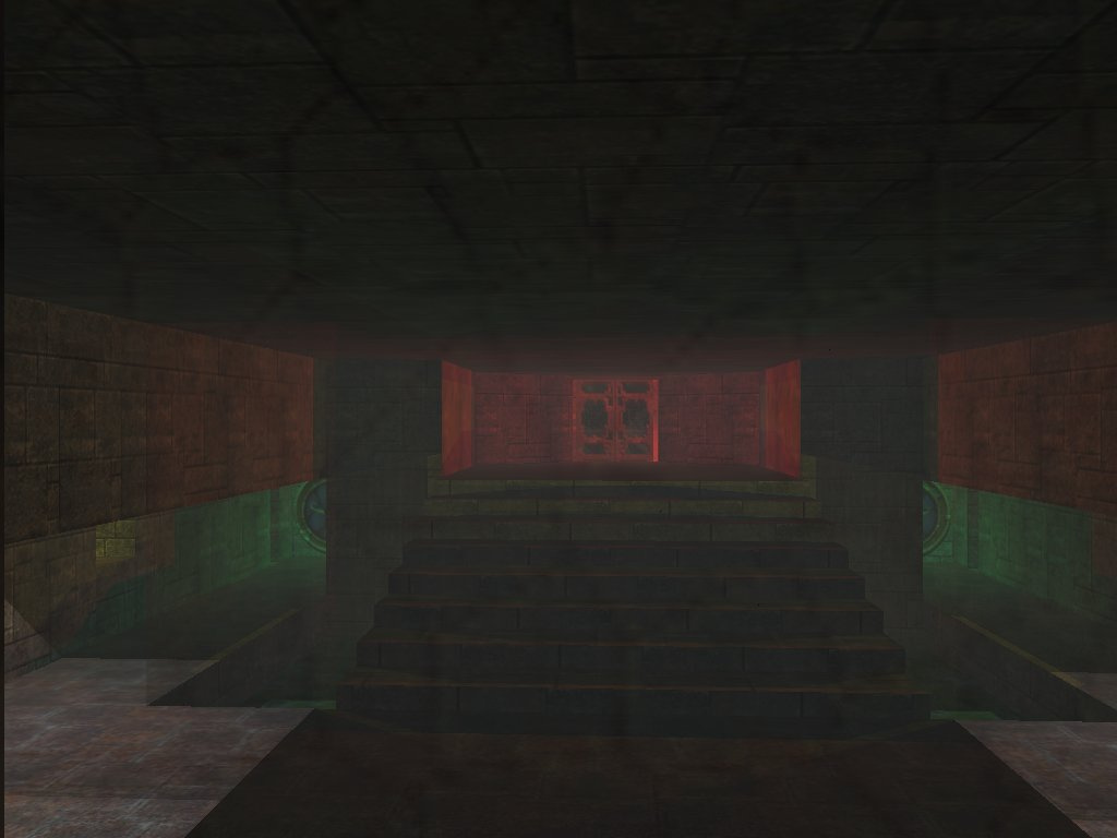
Screenshots of the three-dimensional engine.
As you can see, for the simplest engine, quite beautiful pictures are obtained.
The idea of the algorithm is that the polygon, the source of the shadow (hereinafter - MIT), splits the polygon with its shadow, the receiver of the shadow (hereinafter - MAT) into fragments A, B, C, D, E, as shown in the figure below. You may notice that for fragments A, B, E, D the light source is on, and for fragment C the light source is off.
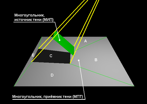
Fragmenting the shadow.
The general algorithm for constructing lighting is as follows:
As a result of this decomposition, we obtain for each source polygon a set of fragments, for each of which it is known which light sources illuminate it. In practice, this means that when displaying these fragments, the engine must enable or disable light sources for which it is precisely known that they do not illuminate this fragment.
Since we only use eight OpenGL light sources, when splitting a scene, you can simply select only those sources from the general list of light sources that most affect the selected polygon of the scene. In the simplest case, this can be done, for example, by calculating the distance from the source to the vertices of the polygon and selecting sources with minimal distances to the vertices. Of course, in this case, some of the sources may be useless for the selected polygon (the source may generally be completely obstructed by another polygon), but the selection algorithm is very simple.
As you can see, the method is simple, however, it will require an algorithm for constructing fragments, knowing the MIT, MPT and the position of the light source.
We agree to consider all polygons to be convex. There is no way, they should be broken into convex parts. To implement the algorithm for finding fragments, we need some functions, namely:
A function that determines the position of a point relative to a certain plane.
Input data:
- Point of the plane ;
- Vector normal to the plane ;
- The point for which the position is determined relative to the plane .
Return value: 1 - the point is above the plane, -1 - the point is below the plane, 0- point is in the plane.
To implement this function, we use the equation of the plane, then $ inline $ \ begin {equation} t = n_ {x} (V_ {x} -P_ {x}) + n_ {y} (V_ {y} -P_ {y}) + n_ {z} (V_ {z } -P_ {z}) \ end {equation} $ inline $ (one).
Received determines the position of a point relative to the plane.
The function should return -1 if , return 1 if and return 0 if .
However, we are working on a bit computer grid, so we cannot compare with zero. Instead, we will hereafter compare with some small , the value of which is easiest to choose empirically so that the algorithm does not give failures.
In this case, the function should return -1 if , return 1 if and return 0 in all other cases.
A function that determines the point of intersection of a line with a plane.
Input data:
- Point of the plane ;
- Vector normal to the plane ;
- The first point is straight ;
- The second point is straight ;
Return value: coordinates of the intersection point, or a flag indicating that there is no intersection.
Vector , specifying the direction of the line is calculated as
Then the scalar product between the normal vector and the straight line vector will be .
If a (In our case, this condition will take the form and ), then the straight line and the plane cannot intersect, because the vectors are perpendicular.
If the intersection is possible, then the coordinates of the intersection point can be obtained by the formulas
The function that determines the point of intersection of the beam with the plane.
Input data:
- Point of the plane ;
- Vector normal to the plane ;
- The first point of the beam (the beginning of the beam) ;
- The second point of the beam .
Return value: coordinates of the intersection point, or a flag indicating that there is no intersection.
The task is reduced to the previous one, but additional conditions for the possibility of intersection appear, since the ray, unlike the straight line, is semi-infinite.
So, if it turns out that for or for (in our case for or for ), then the ray plane does not intersect.
The function that determines the location of a point inside a convex polygon lying in a plane.
Input data:
- Polygon points lying in the same plane ;
- A point located in the plane of the polygon for which its presence inside the polygon is checked .
Return value: a flag indicating whether a point is inside the polygon or not.
The algorithm of the function is as follows:
We introduce a variable = index of the last point of the polygon;
Cycle by from 0 to ;
We introduce variable indices of three consecutive points. , , ;
If a then ;
If a then ;
Take three consecutive points of a polygon. , , ;
Create three vectors: according to the formulas
Calculate vector art and ;
Calculate the scalar product ;
If a (in our case ), then the point inside the polygon does not fall.
End of cycle;
The point falls inside the polygon.
The idea of the function is that three consecutive points of a polygon define two edges of a polygon, transforming them into vectors, you can calculate the vector product of vectors of the first edge with the second and first edges with a vector composed of the first point of the polygon and the point under study.
At the same time, the directions of the resulting vectors depend on which side of the first edge is the point. To calculate the consistency of the resulting vectors, their scalar product is used, which will be negative if the vectors are directed in opposite directions.
Input data:
- Points convex polygon, which is the source of the shadow), lying in the same plane;
- Points a convex polygon on which a shadow is cast) lying in the same plane;
- Point of position of the light source (hereinafter referred to as the IC - “light source”);
Returned data: a flag indicating whether there is a shadow or not, and an array of polygons into which the MAT is divided by a shadow.
Consider the algorithm for obtaining points of the shadow in the coordinate system of MPT.
That's the whole algorithm. All items from 1 to 10 can be viewed in the file shadow.cpp, located in the folder with the lighting demo program.
In the archive by reference (again, not on github - I have not made friends with it yet) there are programs with source codes:
Added links to github:
Engine
Map editor
I must say that this article has been planned for a very long time - years since 2004, when a three-dimensional engine was written using the described method. However, the abundance of formulas and laziness made me soon abandon the writing of the article. The last time I touched the text in 2008. On this date, the article stopped and I did not plan to revive it. But recently, in the topic about the source code for Quake 2 , I was still asked to tell about the technology used to build a picture used in my three-dimensional engine. The relevance of such late articles for modern programming of three-dimensional graphics is, of course, zero, but perhaps beginners in studying OpenGL will find this article interesting.
To begin, I will show exactly what images are obtained when applying the described method. Here are screenshots of my 2004 engine:
')
Screenshots of the three-dimensional engine.
As you can see, for the simplest engine, quite beautiful pictures are obtained.
The idea of the algorithm is that the polygon, the source of the shadow (hereinafter - MIT), splits the polygon with its shadow, the receiver of the shadow (hereinafter - MAT) into fragments A, B, C, D, E, as shown in the figure below. You may notice that for fragments A, B, E, D the light source is on, and for fragment C the light source is off.
Fragmenting the shadow.
The general algorithm for constructing lighting is as follows:
- Choose a light source.
- Each polygon of the scene is divided into fragments by a polygon that can cast a shadow. At the same time, newly obtained fragments will be new polygons of the scene, on which it will be necessary to re-construct shadows from other polygons (but which themselves will not be sources of shadows - it is senseless to use to build a shadow for a part instead of the original whole polygon). Such an operation must be carried out for all polygons of the scene.
- Go to step 1 for the next light source.
As a result of this decomposition, we obtain for each source polygon a set of fragments, for each of which it is known which light sources illuminate it. In practice, this means that when displaying these fragments, the engine must enable or disable light sources for which it is precisely known that they do not illuminate this fragment.
Since we only use eight OpenGL light sources, when splitting a scene, you can simply select only those sources from the general list of light sources that most affect the selected polygon of the scene. In the simplest case, this can be done, for example, by calculating the distance from the source to the vertices of the polygon and selecting sources with minimal distances to the vertices. Of course, in this case, some of the sources may be useless for the selected polygon (the source may generally be completely obstructed by another polygon), but the selection algorithm is very simple.
As you can see, the method is simple, however, it will require an algorithm for constructing fragments, knowing the MIT, MPT and the position of the light source.
Algorithm implementation
We agree to consider all polygons to be convex. There is no way, they should be broken into convex parts. To implement the algorithm for finding fragments, we need some functions, namely:
A function that determines the position of a point relative to a certain plane.
Input data:
- Point of the plane ;
- Vector normal to the plane ;
- The point for which the position is determined relative to the plane .
Return value: 1 - the point is above the plane, -1 - the point is below the plane, 0- point is in the plane.
To implement this function, we use the equation of the plane, then $ inline $ \ begin {equation} t = n_ {x} (V_ {x} -P_ {x}) + n_ {y} (V_ {y} -P_ {y}) + n_ {z} (V_ {z } -P_ {z}) \ end {equation} $ inline $ (one).
Received determines the position of a point relative to the plane.
The function should return -1 if , return 1 if and return 0 if .
However, we are working on a bit computer grid, so we cannot compare with zero. Instead, we will hereafter compare with some small , the value of which is easiest to choose empirically so that the algorithm does not give failures.
In this case, the function should return -1 if , return 1 if and return 0 in all other cases.
A function that determines the point of intersection of a line with a plane.
Input data:
- Point of the plane ;
- Vector normal to the plane ;
- The first point is straight ;
- The second point is straight ;
Return value: coordinates of the intersection point, or a flag indicating that there is no intersection.
Vector , specifying the direction of the line is calculated as
Then the scalar product between the normal vector and the straight line vector will be .
If a (In our case, this condition will take the form and ), then the straight line and the plane cannot intersect, because the vectors are perpendicular.
If the intersection is possible, then the coordinates of the intersection point can be obtained by the formulas
Where - the value obtained by the formula (1).
The function that determines the point of intersection of the beam with the plane.
Input data:
- Point of the plane ;
- Vector normal to the plane ;
- The first point of the beam (the beginning of the beam) ;
- The second point of the beam .
Return value: coordinates of the intersection point, or a flag indicating that there is no intersection.
The task is reduced to the previous one, but additional conditions for the possibility of intersection appear, since the ray, unlike the straight line, is semi-infinite.
So, if it turns out that for or for (in our case for or for ), then the ray plane does not intersect.
The function that determines the location of a point inside a convex polygon lying in a plane.
Input data:
- Polygon points lying in the same plane ;
- A point located in the plane of the polygon for which its presence inside the polygon is checked .
Return value: a flag indicating whether a point is inside the polygon or not.
The algorithm of the function is as follows:
We introduce a variable = index of the last point of the polygon;
Cycle by from 0 to ;
We introduce variable indices of three consecutive points. , , ;
If a then ;
If a then ;
Take three consecutive points of a polygon. , , ;
Create three vectors: according to the formulas
Calculate vector art and ;
Calculate the scalar product ;
If a (in our case ), then the point inside the polygon does not fall.
End of cycle;
The point falls inside the polygon.
The idea of the function is that three consecutive points of a polygon define two edges of a polygon, transforming them into vectors, you can calculate the vector product of vectors of the first edge with the second and first edges with a vector composed of the first point of the polygon and the point under study.
At the same time, the directions of the resulting vectors depend on which side of the first edge is the point. To calculate the consistency of the resulting vectors, their scalar product is used, which will be negative if the vectors are directed in opposite directions.
Algorithm for constructing fragments
Input data:
- Points convex polygon, which is the source of the shadow), lying in the same plane;
- Points a convex polygon on which a shadow is cast) lying in the same plane;
- Point of position of the light source (hereinafter referred to as the IC - “light source”);
Returned data: a flag indicating whether there is a shadow or not, and an array of polygons into which the MAT is divided by a shadow.
Obtaining points of a shadow in the MPT plane
Consider the algorithm for obtaining points of the shadow in the coordinate system of MPT.
- Let us verify that MIT and MPT have at least three points; otherwise, strictly speaking, these are not polygons at all, and there is no shadow.
- Check whether the IP can illuminate the MAT. We will agree that if the IC lies above the MPT plane (the normal MPT is directed toward the IP), then it can illuminate the MPT, otherwise, this is impossible. If the IS cannot illuminate the MAT, then there is no shadow.
- Since MIT can cross MAT, it is necessary to adjust MIT so that it is always higher than MAT. For this you need to cycle through the edges of MIT, leaving points that lie above the plane of the MPT and discarding points that lie below the plane of the MPT, and if the points of any edge are on different sides of the plane defined by the MPT, then you need to add to the new MIT these intersection points. Thus, we will have a new MIT, which lies exactly above the MAT. If after correcting the MIT points there are less than three, then there is no shadow.
- It is possible that MAT and IS are located on the same side of MIT. In this case, too, there is no shadow. This can be checked by determining the position of the IC relative to the MIT plane and comparing with this position the positions of the points of the MPT relative to the MIT plane. If at least one point of MPT lies on the other side of the MIT plane, rather than IP, then a shadow exists, otherwise there is no shadow.
- Now you need to create a shadow volume. Everything that gets into the shadow volume is not illuminated by the IC. The figure defining the shadow volume is bounded above by MIT, nothing restricts it from below (since the volume extends to infinity), and on the sides it is bounded by quadrilateral faces, in which two vertices are also infinite, and the other two coincide with the vertices of the MIT edge .
- Since the MIT is already specified, it is required to find quadrilateral faces. Since all we need from these faces now is that they define planes, we will replace infinite vertices with finite ones. To do this, take the edges of MIT, and let the beam from the IC through the vertices of the edges. For example, take the first two points of MIT and , then the coordinates of the points of the edge of the shadow volume defined asWhere
Since MIT could be oriented as desired, then the normals of the edges of the shadow volume can be directed both inside the volume and outwards. Let us agree that the normals of the shadow volume should be directed outwards.
To do this, compare the position of the point that exactly falls into the shadow volume relative to the planes defined by the edges of the shadow volume. Such a point can be obtained if we find the geometric center of MITand send a beam from the IC through this center, just as it was done to find the vertices of the edges of the shadow volume. If, when determining the position of this point relative to the planes of the faces, it is obtained for any face that the point is above the selected face, then the face should be “flipped”, i.e. change the coordinates of the coordinates of the face normal vector to the opposite. The direction of traversal of the points themselves defining the edge can be left unchanged, since this will not be necessary in the future. - Now we have to find the points of the shadow. First we find the points of MPT lying inside the shadow volume. It is done this way: each point of the MPT needs to be compared with all the planes defined by the edges of the shadow volume, and if it turns out that for all the faces it is below the plane of the face (or in the face), then this point lies exactly inside the shadow volume. After this, it is necessary to find the intersection points of the shadow volume with the MPT. To do this, for each face of the shadow volume, we traverse all the edges of the MPT and find the intersection of the edges with the plane of this particular face, checking whether the intersection point falls inside the shadow volume. However, these are not all the points from which a shadow can gather. We also need the points of intersection of the edges of the shadow volume with MPT. In order to find them, we need to calculate the intersection points of the plane of the MPT and the rays coming out of the IC and passing through the vertices of the MIT, checking that all the obtained points lie inside the MPT. In the end, we should have an array of points from which a shadow is assembled on the MPT plane. However, these points are not yet ordered.
- Further points of the shadow should be transferred to the coordinate system of MPT (will be the XZ plane, where the coordinate Y = 0), that is, project on the plane of the MPT. To sort the points of the shadow, you can take the center of these points (counted as the arithmetic mean of the coordinates in the plane) and sort by the angle (counted through the arctangent ( atan2 ) coordinates) and the distance from the center.
- Now our shadow points are ordered, recalculated into the plane of YGT and it’s time to build fragments. It is quite natural that the first fragment will be the shadow itself (unless, of course, it has stretched into a line (with tolerance due to error), which is also possible - in this case we assume that there is no shadow). Now take each side of the shadow polygon and add to the fragment all those points that are outside the shadow polygon (lie with the center point of the shadow polygon on opposite sides of the selected side of the shadow polygon), as shown in the figure. In addition, you should add the intersection points of the sides of the MAT and a line containing the selected side of the shadow polygon. Of course, the same points should not be added to the coordinates. After adding all the points to the fragment, we cut the MPT around the edges and repeat the operations with the next side of the shadow polygon.
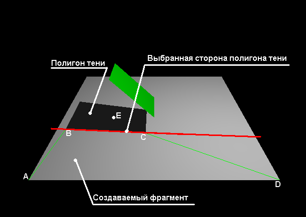
Creating a fragment - Having received all the fragments, we recalculate their coordinates back to a three-dimensional coordinate system that is not associated with MPT.
That's the whole algorithm. All items from 1 to 10 can be viewed in the file shadow.cpp, located in the folder with the lighting demo program.
In the archive by reference (again, not on github - I have not made friends with it yet) there are programs with source codes:
- Lighting demonstration program that builds real-time shadows from two light sources on the pyramid and the plane below it.
- 3D engine using the above technology.
- 3D engine map editor (entirely on Win32API, no OWL or MFC).
Added links to github:
Engine
Map editor
Source: https://habr.com/ru/post/328842/
All Articles