Interactive 3D-installation based on "Star Wars"
Somewhere in a distant galaxy (albeit in ours too), the unofficially Star Wars day is celebrated on May 4th. It is not by chance that he was chosen; from the movie is a quotation confirming “May the Force be with you” (“May the Force be with you”), how does it sound to the fans of “May the fourth be with you”. In this post, we want to congratulate habrovchan, those who have passed to the dark side. We want to tell about the 3D-installation creation. It will be interactive and thematic.

My wife inspired me on this project when we went shopping before Christmas together. The next episode of "Star Wars" just came out, and the shelves in the shops were full of toys from this movie. My wife called me and asked if the Hackster competition on the Star Wars theme had ended. She said she saw some interesting things from which to collect something cool.
As a result, we bought a few toys and came up with a fun interactive installation on the wall.
')
We took a small panel as a basis, placing a sound card on it and, of course, light bulbs so that there was a lot of light. We also installed a motion sensor and an ultrasonic distance sensor to detect people nearby. The light sensor is also present.
Our panel is interactive, it responds to a person standing in front of it or passing by. Darth Vader's eyes light up red, activation and deactivation of the lightsaber are accompanied by sounds that everyone has known since childhood. The Death Star is also used as a night lamp. It turns on in the dark when the motion sensor is triggered. Finally, sometimes Darth Vader talks.
It happens spontaneously, but not constantly. The basic idea is that this should happen “when you least expect it.” So Darth Vader has already scared several members of our family.
To manage the installation, you can also use the universal Windows 10 application and the cloud-based web interface API Particle.io.
This is how it looks now (the entire panel ( 122 x 91 cm )).

The installation consists of four modules that interact with the I2C bus. The main controller is implemented on the basis of the Particle Photon platform, it is responsible for interrogating sensors, managing other cards and communicating through the cloud. There are three more auxiliary controllers based on the Adafruit Trinket Pro 5V , they control the lightsaber, the Death Star, the eyes of Darth Vader, and sound effects.
Thanks to the white LED light, the Death Star is a great night light. Adafruit NeoPixel Jewels LED modules (seven NeoPixels LEDs in each) are installed in the eyes of Darth Vader. The lightsaber is 100 RGBW NeoPixels LEDs (a piece of tape with 144 LEDs per meter). In the helmet of Darth Vader (in the slot for the mouth) and in the Death Star is determined by the dynamics.
Plywood is usually sold in sheets measuring 122 x 244 cm , I cut it to 122 x 91 cm . To finish looked clean and tidy, sheets of higher quality were selected. However, any plywood needs to be lightly pre-processed along the edges and on the front side. To do this, I used 220 grit sandpaper. Then I wiped the treated surfaces with a damp cloth and let them dry completely.
We covered our panel with paint Glidden Blue Gray Sky (30BB 32/067) .

The frame is made of pine slats 2.5 x 5 cm in size (1.9 to 4.45 cm) . The grooves turned out 122 and 91 cm for the long and short sides, respectively. Along the edges of the rails, slices at an angle of 45 ° are added to get a frame for a full-fledged subframe.
Having prepared the slats and squeezing them tightly into place on each side of the board, it is necessary to finally fix them with wood glue and corner clamps. Glue the edges so that the adjacent sides are at right angles.
To reinforce the frame, I used 8 # 18 x 3/4 " wire nails ( 2 pieces for each corner). We need to drill a guide hole for each nail, otherwise we risk splitting the wood. The tip of the nail must be drowned with a small punch.
After the glue dries, fill the corners with wooden putty to get rid of the gaps. It is also necessary to putty the places where the nails were driven.
Before painting, go over the entire surface of the frame with sandpaper, and then wipe the treated surfaces with a damp cloth and dry completely.
We painted the frame with Glidden Gray Metal (00NN 10/000) .

The frame is attached to the panel using small brass hinges, which are sold at any hardware store. A slight overlap in the front can be eliminated with a large stick for mixing paint with a thickness of about 4–5 mm . Next, turn the panel face down and put a stick in order to achieve the desired height. Fasten the hinges on the panel with the attached screws. The guide hole must be drilled for each screw, otherwise we risk splitting the wood. It is important to be careful and leave a gap from the front of the panel each time.
I have only 12 hinges connecting the frame with the board ( 3 along each side). Two lateral hinges are located at a distance of about 13 cm from the inner corner, and the third is centered on the corresponding side. Below is the front side of the panel, it shows a gap between the panel and the frame.

Darth Vader, the lightsaber and the Death Star (these are all fixtures) were sold immediately with stickers that create a special visual effect: they seemed to break through the base. We made the background gray specifically to highlight this effect.
Next, select the optimal placement of these three elements on the panel. Here you can rely on your artistic taste. Having defined the location, we attach the stickers in accordance with the attached instructions. Please note that the instructions say that the painted wall must be given up to two weeks to dry thoroughly. We really waited two weeks before sticking stickers. This is what all three stickers look like.

We bought additional stickers on the Amazon website, and not all of them came in handy from the kit. I think that everyone will decide for himself what quantity and what type of stickers he wants to make.
I enhanced the 3D effect with attack plane models (Hot Wheels TIE Fighters spaceships), attaching them to the panel with a glue gun. You can skip this step.
Included wall fixtures have all the necessary screws to fix the fixtures on the panel. As usual, I recommend to drill the guide holes.
Of all the lamps, you must first remove the built-in electronics. Fortunately, for this you need to unscrew a few screws.
First, remove the back cover from the head of Darth Vader. Next, unscrew the screws holding the LEDs and the switch, cut off the wires leading to the battery compartment. These components may be useful for another project. :)

Then, to prepare the NeoPixel Jewels LED modules, we connect the wires 22 AWG to each of the three terminals. I recommend using the red wire for 5 V , black for grounding and green for the interface. Cut off pieces about 90 cm long and first solder the red wire to contact 5 V of the first Jewel module, then the black wire. Finally, we attach the green wire to the Data In contact.
The next Jewel module will connect to the first one. Cut the wires of three colors again, this time 25 cm . Solder the red wire to the 5 V contacts on the first and second Jewel module. The red wire is soldered to the GND contacts on the first and second Jewel module. Finally, the green wire is to the Data Out contact on the first module and the Data In contact on the second module.

To attach the modules to the plate of the helmet, use the tubes for drinks. They are needed so that the light can be seen through the dark eye sockets. First, cut into pieces of 5 cm (in this example, thicker tubes are used, but the usual ones are also suitable). Next, place the modules closer to the top of the helmet. To attach them to the back of the NeoPixel modules and to the helmet plate, use an adhesive gun. One tube is enough for reliable fixation, but, just in case, I decided to use the second one.

Finally, we need to install the speaker in the helmet. We make it to the plate at the level of the mouth. In the helmet there is a small piece of metal that would muffle the sound, so it needs to be removed. To do this, simply unscrew several screws. Further, with the help of a glue gun, we fix the speaker on the helmet plate.

To remove the wires, we drill a 6 mm (1/4 ") hole in the center of the plate. Don't forget, you will need to attach the plate to the panel without the front of the helmet. Therefore, it is worth drilling new holes in the panel through the holes in the plate. Thus, the wires from the helmet will go through the hole in the plate and the hole in the panel so that they can be assembled into one bundle at the back.

Connecting the LEDs and the speaker, let the wires through the hole and put the helmet plate in place. Do not forget to tighten the screws. :)
Disassembling the lightsaber is a little more difficult. In the end, you should have four separate elements.
First, remove the red plastic tube that mimics the beam. She just unscrews and pulls out. Inside it you will find the second part - a long transparent plastic tube. This is a rolled piece of plastic, on which we will then fix a strip of LEDs NeoPixel. Set this item aside.
The next element to be removed is the base plate. Unscrew the three screws. It should turn out like this.

Next, remove the side of the handle of the lightsaber and remove the entire electronic filling.

After that we cut the NeoPixel ribbon, leaving 100 LEDs on it. If you have never done this, the Adafruit Uberguide guide will be helpful.
Cut off three pieces of wire 22 AWG approximately 60 cm each. We take the red, black and green wires (by the way, personally, I often use green, white or yellow wires as the interface wire for NeoPixel modules), solder the red wire to contact 5 V , black - to contact GND , and green - to contact Data In .
Then very carefully we stretch the NeoPixel tape into a transparent plastic tube, trying not to bend it strongly.

Then we pass the wires through the bottom plate, as shown in the photo below.

Stretching the wires, fasten the side plate with five screws. Then we attach the back panel and pull the wires through the hole in which the switch was located. Where wires will pass through the main panel, it is necessary to drill a hole with a diameter of 6 mm (1/4 ") .
We make a prototype of each scheme, using the images in the spoilers.
Please note that you should be able to assemble circuit board layouts according to schemes.
Note I used:
In the end, we get this scheme.

To implement this part of the project will take considerable time (although, of course not 2 weeks :)), in addition, you should pay close attention to the layout and placement of components on the layouts. By the way, I used Adafruit Perma-Proto mockups.
If everything went well, you will get this result.
After assembling and testing the layouts, the schemes can be transferred to printed circuit boards (in my case, this is Perma-Proto).
Alternately transfer the circuit, soldering the details. It is better that you have spare parts to copy the scheme, rather than transfer it. This will help to avoid mistakes.
Note :
In the spoilers below you will find photos of the resulting schemes.
If everything went well, you will get this result.
I chose the Death Star to place all the electronic components in it. It fits perfectly into the concept and provides enough free space.
First you need to disassemble it and remove all the basic electronics. First, unscrew the screws from the back side, then the screws holding the electronic components, and then cut off the wires from the battery compartment.

The previously collected schemes are fixed on the panel of the Death Star. To do this, use spacers (or pins) M3 , screws M3 , nuts M3 and two washers M3 for each spacer. In total there will be eight spacers (two for each PCB).
We start by attaching brass pins to each board with the M3 nut (for this you may need to remove the Trinket and Photon modules).
Three smaller boards can be placed using existing slots on the plate. For a large board you need to drill holes. Next, from the outside of the plate we screw in the screw and washer, place a large board and mark the points where the pins will be fixed with a pencil. Remove the board and drill holes for the screws. The order of the boards does not matter, so anyone can choose the optimal layout for themselves and then fix the boards.
By analogy with the helmet of Darth Vader, we need a centering hole, which needs to be compared with the hole in the panel. Through it, the wires will go to the back of the panel, where the lightsaber and Darth Vader's helmet will be connected.
I got this layout boards. Pay attention to the hole drilled in the upper left.

Next, connect the two-wire LED backlight connector and fix it with a heat shrink tubing. In the photo below you can see the preparation of the LED.

The second speaker will be installed inside the Death Star. It turned out that the mounting holes on the speaker matched the screws inside the Death Star, as shown below. Therefore, we connect the speaker to the sound card terminals. After that, we fix the LED illumination with the help of a glue gun over the green plastic dome inside the Death Star.

By analogy with the process of mounting the LED, we draw the conclusions of the photoresistor and draw wires through the holes on the right side of the dome (away from the lightsaber). On the inside, we connect the two-wire connector to the photoresistor and place it in the heat shrink tube, as shown below.

At the bottom of the dome, drill holes with a diameter of 1.3 cm (1/2 ") for a motion sensor and an ultrasonic distance sensor. Connect the four-wire connector to each sensor and pull the sensors into the holes, then fix them to the outside of the dome with an adhesive gun.

Next, we cut two sets of three wires 22 AWG approximately 60 cm long for NeoPixel connections and connect them to the terminals on the board. Red wire - for 5V, black - for GND and green (or yellow) - for the interface. Color coding will further simplify the connection of components on the rear panel of the board. With the help of electrical tape and a marker, I marked these wires to easily identify them later (I wrote "lightsaber" and "Darth Vader").
Next, cut off two more wires for the speaker: red and black (it’s better to take 26 AWG , but 22 AWG will work too), and connect them to the terminals. Connect the two-wire socket to the 12 V connector on the Photon board.
At this stage, the wires can be stripped and secured with cable ties and electrical tape. First, we wind up six wires from the NeoPixel, wires from the two speakers and a power wire through the hole in the plate. With the help of electrical tape, so that they cannot be pulled out from the back side of the board, after which we bundle together and tie them together with ties.

Now we collect the Death Star and pass all the wires through the hole in the panel.

At this stage, we connect all the devices. The wires on the back side of the board must be connected using the lugs, after they are secured with tape, using electrical tape or some kind of adhesive fasteners. Do not leave too much margin for the length of the wires, but it should be enough so that, if necessary, you can again remove any of the components.

The software for this project can be divided into three categories.
First is the Photon firmware. This software manages other cards and communicates with them via the I2C bus. Secondly , this is the Arduino code that is loaded into each of the three Trinket Pro modules. Thirdly , this is the Windows 10 UWP software that is used on Windows 10 devices to remotely manage our interactive installation.
The code in the spoiler below is the firmware for Photon. The class files referenced in the code can be found in the GitHub repository for this project .
Below is a screenshot of what we did.
Main screen for managing effects and menus.

Setting up a cloud API for Photon and setting parameters.

The Windows 10 code accesses the Particle.io cloud API using an
The code below shows how to get the value of a variable defined using
All software is available in the GitHub repository for this project . A list of all components for the project and links to their purchase can be found on the website .
This video shows the various effects supported by this interactive installation. In life, the panel is turned on automatically by a signal from the motion sensor.
Introduction
Prehistory
My wife inspired me on this project when we went shopping before Christmas together. The next episode of "Star Wars" just came out, and the shelves in the shops were full of toys from this movie. My wife called me and asked if the Hackster competition on the Star Wars theme had ended. She said she saw some interesting things from which to collect something cool.
As a result, we bought a few toys and came up with a fun interactive installation on the wall.
')
We took a small panel as a basis, placing a sound card on it and, of course, light bulbs so that there was a lot of light. We also installed a motion sensor and an ultrasonic distance sensor to detect people nearby. The light sensor is also present.
Our panel is interactive, it responds to a person standing in front of it or passing by. Darth Vader's eyes light up red, activation and deactivation of the lightsaber are accompanied by sounds that everyone has known since childhood. The Death Star is also used as a night lamp. It turns on in the dark when the motion sensor is triggered. Finally, sometimes Darth Vader talks.
It happens spontaneously, but not constantly. The basic idea is that this should happen “when you least expect it.” So Darth Vader has already scared several members of our family.
To manage the installation, you can also use the universal Windows 10 application and the cloud-based web interface API Particle.io.
This is how it looks now (the entire panel ( 122 x 91 cm )).
Design
The installation consists of four modules that interact with the I2C bus. The main controller is implemented on the basis of the Particle Photon platform, it is responsible for interrogating sensors, managing other cards and communicating through the cloud. There are three more auxiliary controllers based on the Adafruit Trinket Pro 5V , they control the lightsaber, the Death Star, the eyes of Darth Vader, and sound effects.
Thanks to the white LED light, the Death Star is a great night light. Adafruit NeoPixel Jewels LED modules (seven NeoPixels LEDs in each) are installed in the eyes of Darth Vader. The lightsaber is 100 RGBW NeoPixels LEDs (a piece of tape with 144 LEDs per meter). In the helmet of Darth Vader (in the slot for the mouth) and in the Death Star is determined by the dynamics.
Assembly process
Panel
Plywood is usually sold in sheets measuring 122 x 244 cm , I cut it to 122 x 91 cm . To finish looked clean and tidy, sheets of higher quality were selected. However, any plywood needs to be lightly pre-processed along the edges and on the front side. To do this, I used 220 grit sandpaper. Then I wiped the treated surfaces with a damp cloth and let them dry completely.
We covered our panel with paint Glidden Blue Gray Sky (30BB 32/067) .
Frame
The frame is made of pine slats 2.5 x 5 cm in size (1.9 to 4.45 cm) . The grooves turned out 122 and 91 cm for the long and short sides, respectively. Along the edges of the rails, slices at an angle of 45 ° are added to get a frame for a full-fledged subframe.
Having prepared the slats and squeezing them tightly into place on each side of the board, it is necessary to finally fix them with wood glue and corner clamps. Glue the edges so that the adjacent sides are at right angles.
To reinforce the frame, I used 8 # 18 x 3/4 " wire nails ( 2 pieces for each corner). We need to drill a guide hole for each nail, otherwise we risk splitting the wood. The tip of the nail must be drowned with a small punch.
After the glue dries, fill the corners with wooden putty to get rid of the gaps. It is also necessary to putty the places where the nails were driven.
Before painting, go over the entire surface of the frame with sandpaper, and then wipe the treated surfaces with a damp cloth and dry completely.
We painted the frame with Glidden Gray Metal (00NN 10/000) .
Frame mount
The frame is attached to the panel using small brass hinges, which are sold at any hardware store. A slight overlap in the front can be eliminated with a large stick for mixing paint with a thickness of about 4–5 mm . Next, turn the panel face down and put a stick in order to achieve the desired height. Fasten the hinges on the panel with the attached screws. The guide hole must be drilled for each screw, otherwise we risk splitting the wood. It is important to be careful and leave a gap from the front of the panel each time.
I have only 12 hinges connecting the frame with the board ( 3 along each side). Two lateral hinges are located at a distance of about 13 cm from the inner corner, and the third is centered on the corresponding side. Below is the front side of the panel, it shows a gap between the panel and the frame.
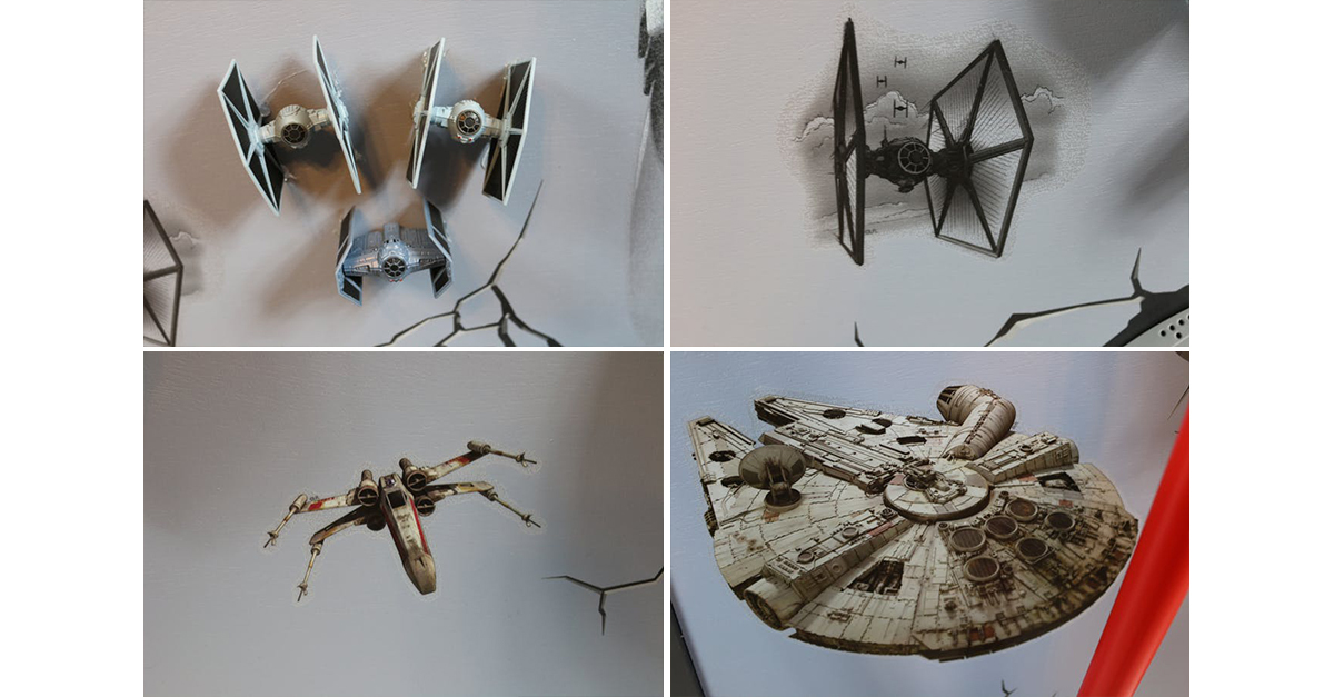
Placing stickers and models
Darth Vader, the lightsaber and the Death Star (these are all fixtures) were sold immediately with stickers that create a special visual effect: they seemed to break through the base. We made the background gray specifically to highlight this effect.
Next, select the optimal placement of these three elements on the panel. Here you can rely on your artistic taste. Having defined the location, we attach the stickers in accordance with the attached instructions. Please note that the instructions say that the painted wall must be given up to two weeks to dry thoroughly. We really waited two weeks before sticking stickers. This is what all three stickers look like.
We bought additional stickers on the Amazon website, and not all of them came in handy from the kit. I think that everyone will decide for himself what quantity and what type of stickers he wants to make.
I enhanced the 3D effect with attack plane models (Hot Wheels TIE Fighters spaceships), attaching them to the panel with a glue gun. You can skip this step.
Included wall fixtures have all the necessary screws to fix the fixtures on the panel. As usual, I recommend to drill the guide holes.
Darth Vader Helmet
Of all the lamps, you must first remove the built-in electronics. Fortunately, for this you need to unscrew a few screws.
First, remove the back cover from the head of Darth Vader. Next, unscrew the screws holding the LEDs and the switch, cut off the wires leading to the battery compartment. These components may be useful for another project. :)
Then, to prepare the NeoPixel Jewels LED modules, we connect the wires 22 AWG to each of the three terminals. I recommend using the red wire for 5 V , black for grounding and green for the interface. Cut off pieces about 90 cm long and first solder the red wire to contact 5 V of the first Jewel module, then the black wire. Finally, we attach the green wire to the Data In contact.
The next Jewel module will connect to the first one. Cut the wires of three colors again, this time 25 cm . Solder the red wire to the 5 V contacts on the first and second Jewel module. The red wire is soldered to the GND contacts on the first and second Jewel module. Finally, the green wire is to the Data Out contact on the first module and the Data In contact on the second module.
To attach the modules to the plate of the helmet, use the tubes for drinks. They are needed so that the light can be seen through the dark eye sockets. First, cut into pieces of 5 cm (in this example, thicker tubes are used, but the usual ones are also suitable). Next, place the modules closer to the top of the helmet. To attach them to the back of the NeoPixel modules and to the helmet plate, use an adhesive gun. One tube is enough for reliable fixation, but, just in case, I decided to use the second one.
Finally, we need to install the speaker in the helmet. We make it to the plate at the level of the mouth. In the helmet there is a small piece of metal that would muffle the sound, so it needs to be removed. To do this, simply unscrew several screws. Further, with the help of a glue gun, we fix the speaker on the helmet plate.
To remove the wires, we drill a 6 mm (1/4 ") hole in the center of the plate. Don't forget, you will need to attach the plate to the panel without the front of the helmet. Therefore, it is worth drilling new holes in the panel through the holes in the plate. Thus, the wires from the helmet will go through the hole in the plate and the hole in the panel so that they can be assembled into one bundle at the back.
Connecting the LEDs and the speaker, let the wires through the hole and put the helmet plate in place. Do not forget to tighten the screws. :)
Lightsaber
Disassembling the lightsaber is a little more difficult. In the end, you should have four separate elements.
First, remove the red plastic tube that mimics the beam. She just unscrews and pulls out. Inside it you will find the second part - a long transparent plastic tube. This is a rolled piece of plastic, on which we will then fix a strip of LEDs NeoPixel. Set this item aside.
The next element to be removed is the base plate. Unscrew the three screws. It should turn out like this.
Next, remove the side of the handle of the lightsaber and remove the entire electronic filling.
After that we cut the NeoPixel ribbon, leaving 100 LEDs on it. If you have never done this, the Adafruit Uberguide guide will be helpful.
Cut off three pieces of wire 22 AWG approximately 60 cm each. We take the red, black and green wires (by the way, personally, I often use green, white or yellow wires as the interface wire for NeoPixel modules), solder the red wire to contact 5 V , black - to contact GND , and green - to contact Data In .
Then very carefully we stretch the NeoPixel tape into a transparent plastic tube, trying not to bend it strongly.
Then we pass the wires through the bottom plate, as shown in the photo below.
Stretching the wires, fasten the side plate with five screws. Then we attach the back panel and pull the wires through the hole in which the switch was located. Where wires will pass through the main panel, it is necessary to drill a hole with a diameter of 6 mm (1/4 ") .
Layout
We make a prototype of each scheme, using the images in the spoilers.
Main controller and lightsaber controllerScheme (main controller)
Scheme (lightsaber controller)
How did I doSound controllerScheme
How did I doDeath Star / Darth Vader Eye ControllerScheme
How did I do
Death Star Controller close-up
Darth Vader eye controller close-upAdditionallySo look the other parts.
Motion sensor, ultrasonic sensor and NeoPixel ring (top to bottom)
One NeoPixel module for testing the eyes of Darth Vader
12V miniature wiring board for all boards


Please note that you should be able to assemble circuit board layouts according to schemes.
Note I used:
- additional high single-row circuit boards with leads in its layout, and then standard circuit boards with leads during soldering on printed circuit boards;
- NeoPixel ring instead of NeoPixel ribbon (for a lightsaber);
- one NeoPixel module instead of two (for eyes);
- miniature circuit board for 12 V wiring to all other boards.
In the end, we get this scheme.
To implement this part of the project will take considerable time (although, of course not 2 weeks :)), in addition, you should pay close attention to the layout and placement of components on the layouts. By the way, I used Adafruit Perma-Proto mockups.
If everything went well, you will get this result.
Printed circuit boards
After assembling and testing the layouts, the schemes can be transferred to printed circuit boards (in my case, this is Perma-Proto).
Alternately transfer the circuit, soldering the details. It is better that you have spare parts to copy the scheme, rather than transfer it. This will help to avoid mistakes.
Note :
- I used standard single-row circuit boards with leads for power connections and I2C connections. For wiring power separated by two contacts. For I2C separated by three contacts.
- Took 3-pin terminal blocks for two NeoPixel connections. These are 3.5 mm parts. They should be soldered to the board diagonally.
- Also, I used the 1.5 -pin ( 1.5 ") IC Sockets 28-pin connectors for Trinket Pro.
- To accommodate the Photon module, I took 0.25-centimeter (0.1 ") 36-pin mounting connectors with leads. I cut off two sets of 12 pins each for the Photon module.
- To connect a coin-type battery to the GND and VBAT pins of the Photon module, I took two pins from the mounting socket with the leads.
- At least two wiring diagrams require a double set of circuit boards for 12 V jumpers, or you can use 3 sets for one of the diagrams. Power will be supplied from the back of the panel, and it must be diluted across all the boards.
- I2C bus must be connected to each circuit board. For this, I soldered two sets of circuit boards for at least two circuits.
In the spoilers below you will find photos of the resulting schemes.
General formCloseup side viewDeath Star / Darth Vader Eye ControllerMain controllerLight sword controller


If everything went well, you will get this result.
The Death Star
I chose the Death Star to place all the electronic components in it. It fits perfectly into the concept and provides enough free space.
First you need to disassemble it and remove all the basic electronics. First, unscrew the screws from the back side, then the screws holding the electronic components, and then cut off the wires from the battery compartment.
The previously collected schemes are fixed on the panel of the Death Star. To do this, use spacers (or pins) M3 , screws M3 , nuts M3 and two washers M3 for each spacer. In total there will be eight spacers (two for each PCB).
We start by attaching brass pins to each board with the M3 nut (for this you may need to remove the Trinket and Photon modules).
Three smaller boards can be placed using existing slots on the plate. For a large board you need to drill holes. Next, from the outside of the plate we screw in the screw and washer, place a large board and mark the points where the pins will be fixed with a pencil. Remove the board and drill holes for the screws. The order of the boards does not matter, so anyone can choose the optimal layout for themselves and then fix the boards.
By analogy with the helmet of Darth Vader, we need a centering hole, which needs to be compared with the hole in the panel. Through it, the wires will go to the back of the panel, where the lightsaber and Darth Vader's helmet will be connected.
I got this layout boards. Pay attention to the hole drilled in the upper left.
Next, connect the two-wire LED backlight connector and fix it with a heat shrink tubing. In the photo below you can see the preparation of the LED.
The second speaker will be installed inside the Death Star. It turned out that the mounting holes on the speaker matched the screws inside the Death Star, as shown below. Therefore, we connect the speaker to the sound card terminals. After that, we fix the LED illumination with the help of a glue gun over the green plastic dome inside the Death Star.
By analogy with the process of mounting the LED, we draw the conclusions of the photoresistor and draw wires through the holes on the right side of the dome (away from the lightsaber). On the inside, we connect the two-wire connector to the photoresistor and place it in the heat shrink tube, as shown below.
At the bottom of the dome, drill holes with a diameter of 1.3 cm (1/2 ") for a motion sensor and an ultrasonic distance sensor. Connect the four-wire connector to each sensor and pull the sensors into the holes, then fix them to the outside of the dome with an adhesive gun.
Next, we cut two sets of three wires 22 AWG approximately 60 cm long for NeoPixel connections and connect them to the terminals on the board. Red wire - for 5V, black - for GND and green (or yellow) - for the interface. Color coding will further simplify the connection of components on the rear panel of the board. With the help of electrical tape and a marker, I marked these wires to easily identify them later (I wrote "lightsaber" and "Darth Vader").
Next, cut off two more wires for the speaker: red and black (it’s better to take 26 AWG , but 22 AWG will work too), and connect them to the terminals. Connect the two-wire socket to the 12 V connector on the Photon board.
At this stage, the wires can be stripped and secured with cable ties and electrical tape. First, we wind up six wires from the NeoPixel, wires from the two speakers and a power wire through the hole in the plate. With the help of electrical tape, so that they cannot be pulled out from the back side of the board, after which we bundle together and tie them together with ties.
Now we collect the Death Star and pass all the wires through the hole in the panel.
At this stage, we connect all the devices. The wires on the back side of the board must be connected using the lugs, after they are secured with tape, using electrical tape or some kind of adhesive fasteners. Do not leave too much margin for the length of the wires, but it should be enough so that, if necessary, you can again remove any of the components.
Software and applications
The software for this project can be divided into three categories.
First is the Photon firmware. This software manages other cards and communicates with them via the I2C bus. Secondly , this is the Arduino code that is loaded into each of the three Trinket Pro modules. Thirdly , this is the Windows 10 UWP software that is used on Windows 10 devices to remotely manage our interactive installation.
The code in the spoiler below is the firmware for Photon. The class files referenced in the code can be found in the GitHub repository for this project .
Some code :)
#include "Controller.h" #include "HC-SR04.h" #include "SensorSmoothing.h" // *** // *** , HC-SR04. // *** #define TRIGGER_PIN D2 #define ECHO_PIN D3 // *** // *** // *** #define MOTION_OUT D4 #define MOTION_ENABLED D5 // *** // *** // *** #define PHOTORESISTOR_PIN A0 // *** // *** // *** #define NUMBER_OF_SAMPLES 5 // *** // *** // *** #define DEFALT_VOLUME 15 // *** // *** , // *** . // *** retained int _volume = DEFALT_VOLUME; // *** // *** . // *** Controller _controller = Controller(); // *** // *** HcSr04 // *** HC-SR04 ( ). // *** HcSr04 _ranging = HcSr04(); // *** // *** // *** . // *** bool _motion = false; // *** // *** // *** . // *** double _distance = 0.0; // *** // *** . // *** int _light = 0; // *** // *** // *** NUMBER_OF_SAMPLES. // *** // *** . // *** SensorSmoothing<double> _distanceSample = SensorSmoothing<double>(NUMBER_OF_SAMPLES); // *** // *** // *** Timer _sensorTimer(1000, onSensorTimer); // *** // *** // *** int _lastEventTime = 0; // *** // *** // *** #define DEFAULT_LIGHT_THRESHOLD 1000 retained int _lightThreshold = DEFAULT_LIGHT_THRESHOLD; bool _lightBelowThreshold = false; bool _deathStarIsOn = false; // *** // *** // *** retained int _minimumEventTime = 20; // retained int _minimumDistance = 127; // void setup() { // *** // *** // *** Particle.publish("Setup", "Started"); // *** // *** // *** STARTUP(System.enableFeature(FEATURE_RETAINED_MEMORY)); // *** // *** HC-SR04 ( ) // *** _ranging.begin(TRIGGER_PIN, ECHO_PIN); // *** // *** I2C // *** Wire.begin(); // *** // *** // *** _controller.begin(_volume); // *** // *** D7 // *** // *** pinMode(D7, OUTPUT); digitalWrite(D7, LOW); // *** // *** // *** Particle.variable("motion", _motion); Particle.variable("distance", _distance); Particle.variable("light", _light); // *** // *** . // *** Particle.function("controller", controllerWebApi); Particle.function("parameter", parameterWebApi); Particle.function("test", testWebApi); // *** // *** // *** . // *** _lastEventTime = Time.now(); // *** // *** . // *** _sensorTimer.start(); // *** // *** , // *** . // *** delay(3000); // *** // *** // *** _controller.darthVaderOff(); _controller.lightSaberOff(); _controller.deathStarOff(); // *** // *** // *** Particle.publish("Setup", "Completed"); } void loop() { // *** // *** _lightBelowThreshold // *** bool previousLightBelowThreshold = _lightBelowThreshold; // *** // *** // *** if (_motion) { // *** // *** // *** // *** . // *** if (_light < _lightThreshold) { if (!previousLightBelowThreshold) { Particle.publish("Light", "Below Threshold"); } _lightBelowThreshold = true; // *** // *** . // *** _deathStarIsOn = true; _controller.deathStarOn(); } else { if (previousLightBelowThreshold) { Particle.publish("Light", "Above Threshold"); } _lightBelowThreshold = false; } // *** // *** , . // *** if (_distance < _minimumDistance) { // *** // *** , // *** // *** . // *** if ((Time.now() - _lastEventTime) > _minimumEventTime) { Particle.publish("Object", "Detected"); _lastEventTime = Time.now(); _controller.randomEvent(); } } } else { // *** // *** . // *** if (_deathStarIsOn) { // *** // *** , // *** . // *** _deathStarIsOn = false; _controller.deathStarOff(); } } // *** // *** // *** delay(150); } void onSensorTimer() { // *** // *** // *** bool previousMotion = _motion; // *** // *** . // *** _motion = (digitalRead(MOTION_OUT) == HIGH); // *** // *** // *** . // *** if (!previousMotion && _motion) { Particle.publish("Motion", "Detected"); if (_lightBelowThreshold) { Particle.publish("Light Level", "Below Threshold: " + String(_light) + "/" + String(_lightThreshold)); } else { Particle.publish("Light Level", "Above Threshold: " + String(_light) + "/" + String(_lightThreshold)); } // *** // *** // *** , . // *** Particle.publish("Distance", String(String(_distance / 2.54).toInt()) + " in / " + String(String(_minimumDistance / 2.54).toInt()) + " in"); // *** // *** // *** . // *** Particle.publish("Time", "Last Event: " + String(Time.now() - _lastEventTime) + " second(s) ago"); } else if (previousMotion && !_motion) { Particle.publish("Motion", "Reset"); } // *** // *** // *** // *** _distance = getRangeEx(); // *** // *** // *** _light = analogRead(PHOTORESISTOR_PIN); } // *** // *** -API // *** int testWebApi(String command) { // *** // *** // *** Particle.publish("Test", "Running"); _controller.setVolume(10); delay(500); _controller.darthVaderOn(); delay(1000); _controller.darthVaderVoice(0); delay(18000); _controller.darthVaderOff(); delay(3000); _controller.darthVaderOn(); delay(1000); _controller.darthVaderVoice(1); delay(5000); _controller.darthVaderOff(); delay(3000); _controller.darthVaderOn(); delay(1000); _controller.darthVaderVoice(2); delay(5000); _controller.darthVaderOff(); delay(3000); _controller.darthVaderOn(); delay(1000); _controller.darthVaderVoice(3); delay(5000); _controller.darthVaderOff(); delay(3000); _controller.darthVaderOn(); delay(1000); _controller.darthVaderVoice(4); delay(5000); _controller.darthVaderOff(); delay(3000); _controller.darthVaderOn(); delay(1000); _controller.darthVaderVoice(5); delay(5000); _controller.darthVaderOff(); delay(3000); _controller.darthVaderOn(); delay(1000); _controller.darthVaderVoice(6); delay(5000); _controller.darthVaderOff(); delay(3000); _controller.darthVaderOn(); delay(1000); _controller.darthVaderVoice(7); delay(5000); _controller.darthVaderOff(); delay(3000); _controller.darthVaderOn(); delay(1000); _controller.darthVaderVoice(8); delay(5000); _controller.darthVaderOff(); delay(3000); _controller.lightSaberOn(7000); delay(2000); _controller.deathStarOn(); delay(5000); _controller.deathStarOff(); Particle.publish("Test", "Completed"); return 1; } // *** // *** -API // *** int parameterWebApi(String command) { int returnValue = 0; // *** // *** // *** , , // *** . // *** int equalIndex = command.indexOf("="); // *** // *** // *** . // *** if (equalIndex > 0) { // *** // *** . // *** String parameterName = command.substring(0, equalIndex); String value = command.substring(equalIndex + 1, command.length()); if (parameterName == "volume") { _volume = value.toInt(); _controller.setVolume(_volume); } else if (parameterName == "minimumDistance") { _minimumDistance = value.toInt(); } else if (parameterName == "lightThreshold") { _lightThreshold = value.toInt(); } else if (parameterName == "minimumEventTime") { _minimumEventTime = value.toInt(); } // *** // *** . // *** Particle.publish("Set Parameter", parameterName + " = " + value); // *** // *** . // *** returnValue = value.toInt(); } else if (equalIndex == -1) { // *** // *** , // *** . // *** if (command == "volume") { returnValue = _volume; } else if (command == "minimumDistance") { returnValue = _minimumDistance; } else if (command == "lightThreshold") { returnValue = _lightThreshold; } else if (command == "minimumEventTime") { returnValue = _minimumEventTime; } // *** // *** . // *** Particle.publish("Get Parameter", command); } else if (command == "reset") { // *** // *** . // *** _volume = DEFALT_VOLUME; _controller.setVolume(_volume); _minimumDistance = 50 * 2.54; _lightThreshold = 1000; _minimumEventTime = 20; _lightThreshold = DEFAULT_LIGHT_THRESHOLD; // *** // *** . // *** Particle.publish("Reset Parameters", ""); returnValue = 1; } return returnValue; } // *** // *** -API // *** int controllerWebApi(String command) { int returnValue = 0; // *** // *** . // *** Particle.publish("Controller", command); // *** // *** . // *** returnValue = _controller.executeCommand(command); return returnValue; } double getRangeEx() { double returnValue = 0; // *** // *** . // *** Range range; if (_ranging.getRange(&range)) { // *** // *** . // *** _distanceSample.addSample(range.distance); // *** // *** . // *** returnValue = _distanceSample.average(); } else { // *** // *** . // *** if (range.result == timeFailed) { switch (range.pingTime.result) { case alreadyActive: Particle.publish("Result", "The sensor is busy."); break; case timeout: Particle.publish("Result", "The sensor did not respond."); break; } } else if (range.result == underRange) { switch (range.result) { case underRange: Particle.publish("Result", "The object is too close."); break; case overRange: Particle.publish("Result", "No object is in range."); break; } } else { Particle.publish("Result", "Unknown Error."); } } return returnValue; } Below is a screenshot of what we did.
Main screen for managing effects and menus.
Setting up a cloud API for Photon and setting parameters.
The Windows 10 code accesses the Particle.io cloud API using an
HttpClient to perform certain functions using Particle.function() , as shown below. protected async virtual Task<int> Execute(string functionName, string command) { int returnValue = 0; HttpClient httpClient = new HttpClient(); HttpRequestMessage request = new HttpRequestMessage(); var values = new List<KeyValuePair<string, string>> { new KeyValuePair<string, string>("args", command) }; FormUrlEncodedContent content = new FormUrlEncodedContent(values); request.Headers.Authorization = this.Identity.Authentication; request.Method = this.Method; request.RequestUri = new Uri(this.Identity.BaseUri, string.Format(this.Resource, functionName)); request.Content = content; HttpResponseMessage response = await httpClient.SendAsync(request); if (response.IsSuccessStatusCode) { string json = await response.Content.ReadAsStringAsync(); dynamic obj = JsonConvert.DeserializeObject(json); string value = obj.return_value; returnValue = Convert.ToInt32(value); } else { throw new HttpRequestException(response.ReasonPhrase); } return returnValue; } The code below shows how to get the value of a variable defined using
Particle.variable() . protected async override Task<T> Execute(params string[] args) { T returnValue = default(T); HttpClient httpClient = new HttpClient(); HttpRequestMessage request = new HttpRequestMessage(); request.Headers.Authorization = this.Identity.Authentication; request.Method = HttpMethod.Get; request.RequestUri = new Uri(this.Identity.BaseUri, string.Format(this.Resource, args)); HttpResponseMessage response = await httpClient.SendAsync(request); if (response.IsSuccessStatusCode) { string json = await response.Content.ReadAsStringAsync(); dynamic obj = JsonConvert.DeserializeObject(json); string value = obj.result; returnValue = (T)Convert.ChangeType(value, typeof(T)); } else { await this.OnFailed(response); } return returnValue; } All software is available in the GitHub repository for this project . A list of all components for the project and links to their purchase can be found on the website .
How it works
This video shows the various effects supported by this interactive installation. In life, the panel is turned on automatically by a signal from the motion sensor.
Source: https://habr.com/ru/post/328022/
All Articles