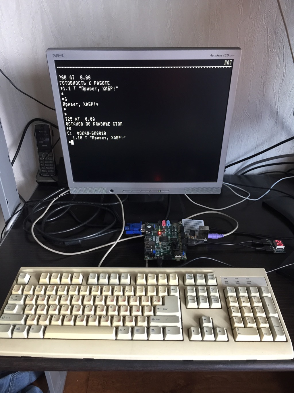
BK-0010 emulator on FPGA
Most amateur projects FPGA, published on Habré, made on the equipment of the company Altera (now Intel). Let's take a look at what can be done on the products of its main competitor - Xilinx. We will take and make a fairly large and complex project, in the process of implementation of which we will need:
- Select Development board and necessary PMOD to it.
- Decide on the design of the project, select the clock domains and the transition rules between them.
- Master the basic functions of Xilinx Vivado - creating a project, working with block schemes, compilation, simulation, debugging
- Make multiple IPs with AXI4 interface
- Work with external devices
- Make your own processor from scratch with a bus controller and interrupt handling
- Write a module for verification
- Finally, put everything together and get the FPGA implementation of the legendary (at least for those who then lived) computer of the mid-80s - BK-0010
A series of articles is planned, in which all of this will be described in detail, today the first of them. The project is written on System Verilog with small inserts Verilog and VHDL where it is needed. The reader is required to understand the basic principles of Verilog / VHDL languages at the Harris & Harris book level.
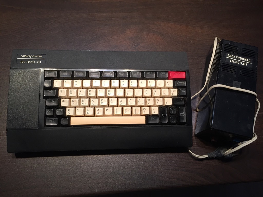
A few words about the BK-0010
The BK-0010 appeared in 1986 and was a single-board computer based on the KR1801BM1 processor (DEC PDP-11 command system). As the story goes, we’ll have to consider some of its architectural features, but for the time being we’ll confine ourselves to those characteristics of a computer that will be important for us to choose a card and other equipment:
| Characteristic | Value |
|---|---|
| CPU | 3 MHz, the number of transistors is about 18000 (n-MOS) |
| Ram | 32 KB |
| ROM | 8-32 KB |
Output devices
')
- Home TV, 512x256 in black and white or 256x256 in color (each point could have 4 colors independently of the others)
- Sound tweeter (output 1 bit), combined with the output to a tape recorder
Input Devices
- Keyboard with the location of the keys JCUKEN
Board selection
What fee and on which crystal to take for the project? In the case of a crystal, our requirements can be selected from Artix-7 and Zynq-7000, in both cases the smallest crystal will suffice. Boards for development - something Xilinx does itself, these are boards with a very rich filling, but with a four-digit price tag. There is a European company Trenz Electronic GmbH, but I would say that their products are more focused on the creation of ready-made devices. In my opinion, the most suitable boards with Xilinx chips for amateur use are made by Digilent. On Artix-7, this is Basys-3, Nexus 4 DDR and Nexus Video, on Zynq-7000, this is Zybo and ZedBoard.
For myself, I stopped at the Zybo. This board is one of the cheapest ($ 189, and if you convince Digilent that you meet the requirements of the Academic Discount Program, then $ 125), it has both VGA and HDMI outputs, many PMOD ports, 512MB RAM. Yes, this board is based on SoC, and I do not plan to use the capabilities of the processor core in this project. But no one bothers to use this board just as FPGA. The board does not have seven-segment debug indicators and no PS2 or USB keyboard can be connected to the FPGA part (unlike the more expensive Nexus 4 DDR), but the price difference between the two boards is much more than the cost of PMOD modules, on which this functionality can receive.
So, in the dry residue, for the project we need the following equipment:
Zybo

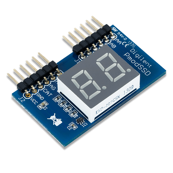
PMOD-SSD - two seven-segment indicators for debugging
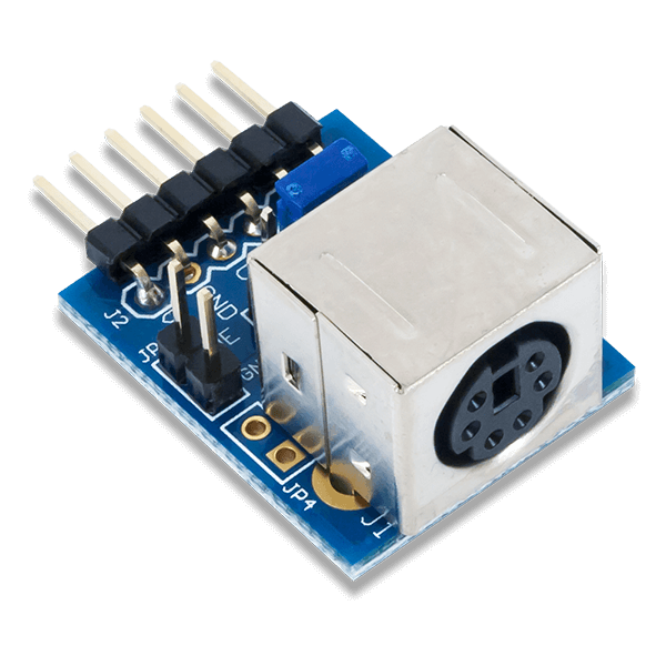
PMOD-PS2 - for connecting a PS / 2 keyboard. I am so ready to buy, I forgot, so I had to make it myself. At the same time I put DC-DC converter 3.3-> 5V there because the keyboard I have from 3.3V did not work.
I do not want to use an outdated PS / 2, but I want to connect a keyboard via USB.
It is possible and so, but there are some difficulties.
There is a USB Host on the Zybo, but it is connected to the PS part. If a PL project is planned, then you will need to connect a separate USB host to the board.
The full specification of the USB protocol (with support for HOST and all types of devices) is very difficult to implement on FPGA, and the USB interface is quite high-frequency. A reasonable compromise is to connect an external physical layer converter, for example, via the ULPI interface; to work with the ULPI, you can find a complete IP module on Verilog / VHDL. You can also choose another motherboard that already has a USB host for working with keyboards and mice (in Digilent this is, for example, Nexus 4 DDR).
Getting started with Xilinx Vivado
Projects for Xilinx (in this case, talking about the 7th series of chips) are created in Xilinx Vivado. Since we are not planning to use High-end chips (UltraSCALE / UltraSCALE +), the free Xilinx Vivado WebPACK edition is suitable for our purposes. We register on xilinx.com, download it and install it.
System requirements
This is mainly RAM. For Zybo it is difficult, but 8GB is enough, for more powerful chips you need more.
To work with Zybo, we will need to download and add to Vivado the Vivado Board Files package containing the description of the interfaces available on the board, the frequency characteristics of the chip, and the like. Download it from the site Digilent (or rather from GitHub ) and add it to Vivado.
You will also need a resource file, which describes the correspondence of the contacts of the chip to the pin numbers of the connectors of the board. We find our board, in this case Zybo on GitHub / Digilent and download.
And finally, we will do the first project on Verilog. We will need this project in the future to create the keyboard controller BK-0010.
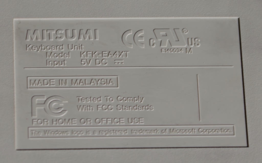
I have such a rare Mitsumi keyboard with PS / 2 interface:
ishevchuk in his project used this controller to work with a PS / 2 keyboard.
Take it and we slightly redo it. The controller is all good except that the clock frequency of 50 MHz is rigidly sewn into it. Such frequency in our project BK-0010 will not be, moreover, hardcoded such things is not good. Create a new project in Vivado, download the controller files and set the clock frequency as a parameter:
Formula header with formulas
module Altera_UP_PS2_Command_Out # ( parameter CLOCK = 100, // Timing info for initiating Host-to-Device communication // when using a 50MHz system clock parameter CLOCK_CYCLES_FOR_101US = (CLOCK * 101), // 5050; parameter NUMBER_OF_BITS_FOR_101US = $clog2(CLOCK_CYCLES_FOR_101US), parameter COUNTER_INCREMENT_FOR_101US = 1, // Timing info for start of transmission error // when using a 50MHz system clock parameter CLOCK_CYCLES_FOR_15MS = (CLOCK * 15000), // 750000; parameter NUMBER_OF_BITS_FOR_15MS = $clog2(CLOCK_CYCLES_FOR_15MS), parameter COUNTER_INCREMENT_FOR_15MS = 1, // Timing info for sending data error // when using a 50MHz system clock parameter CLOCK_CYCLES_FOR_2MS = (CLOCK * 2000), // 100000; parameter NUMBER_OF_BITS_FOR_2MS = $clog2(CLOCK_CYCLES_FOR_2MS), parameter COUNTER_INCREMENT_FOR_2MS = 1 ) Some of the modules in the project in their name have the word Altera. On Xilinx, this does not prevent them from working, out of respect for the developer, I did not rename them.
In addition, we change the polarity of the RESET signal; for standard IP Xilinx, a reset occurs when 0 is applied to the RESET input.
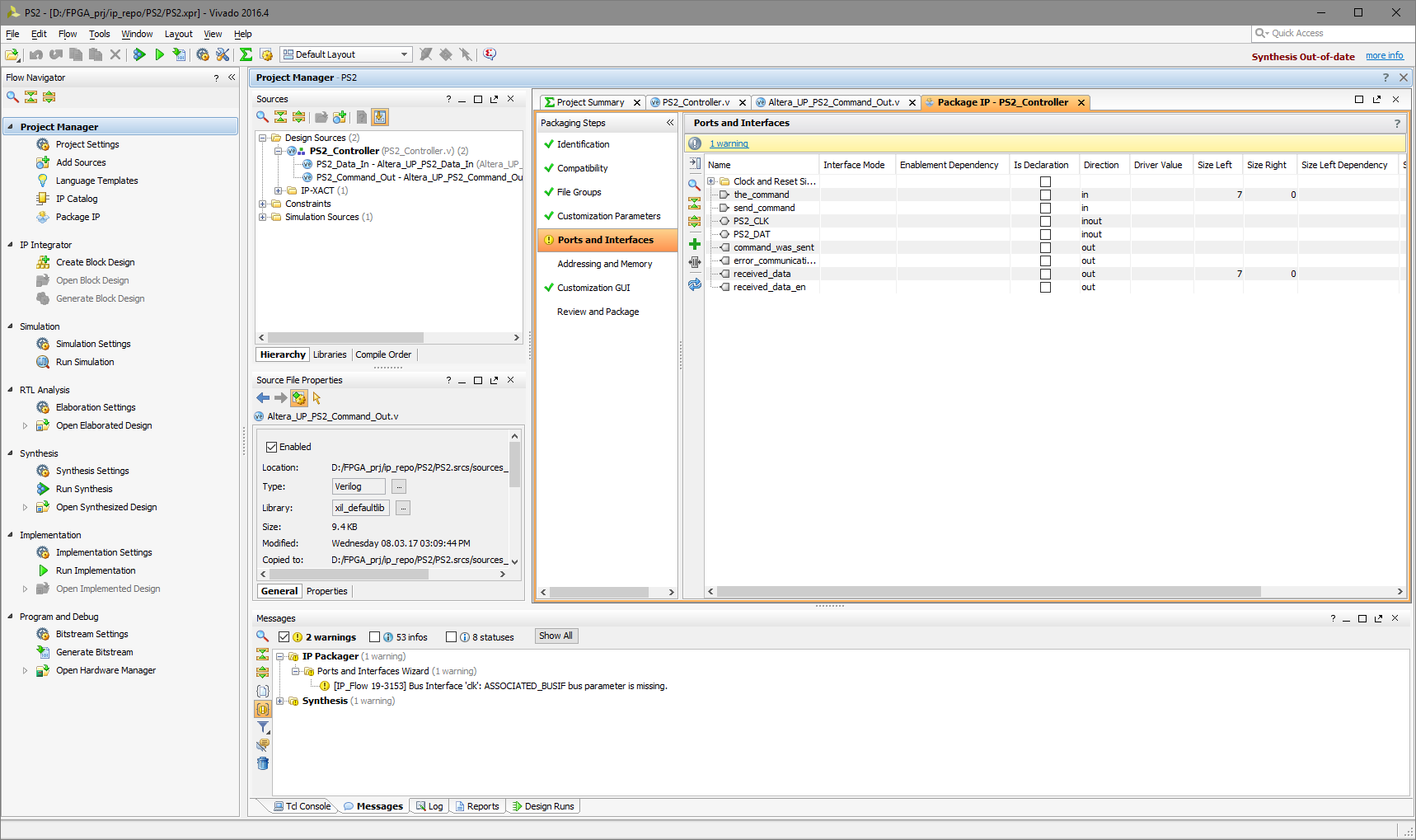
For convenience, let's design the project in the form of IP. In Vivado there is a built-in tool that does this, it is called via Tools-> Create and Package new IP. The inputs and outputs of the project head file will become the inputs and outputs of our new IP. Vivado tries to determine the type of ports by analyzing their name. In this case, we will have to intervene in this process and exclude the PS2_CLK port from the Clock and Reset Signals to reduce the number of Warnings during the further assembly of the project. PS2_CLK cannot be called a full-fledged clock signal, since its frequency is only a few tens of kilohertz.
The tool is very flexible, we can not only set the type of ports, but also manage various parameters, set the conditional compilation options, change the appearance of IP depending on the parameters. In this project, we have two parameters - Initialize Mouse (device selection - keyboard or mouse) and Clock (clock frequency in megahertz). We will consider the issues of conditional compilation later when we write a module for working with the MPI bus.
Connect Git to Vivado
Finally (and in general, of course, this should be done immediately after the creation of a new project) to Vivado Git. Verilog / VHDL source texts, constraints, component descriptions, IP module interface descriptions, the project itself and so on are text files, everything is simple with them. But there is one difficulty - in the project file (it is in XML format) there are absolute paths to the source code, this can cause some problems when transferring the project between machines. One of the solutions is to use a ready-made tool (written by Xilinx engineers), this tool based on the Vivado project creates a portable tcl script that, when launched on the target machine, creates a project there that is identical to the original one. A wrapper has been added to this tool, automating the creation of a tcl script, filling in the .gitignore file, handling input errors and the like. After installing this wrapper , it is possible to work with Git directly from the Vivado tcl console.
Fill the project in iron
Let's check now how it all works. Close the project of the PS2 controller and create a test project that receives scan codes from the keyboard and issues them to the seven-segment indicator. In this project, we will not write a single line of Verilog-code, but we will assemble a scheme from ready-made IP modules.
In IP Integrator we create a new block design, add an IP into it and connect them until such a scheme is obtained:
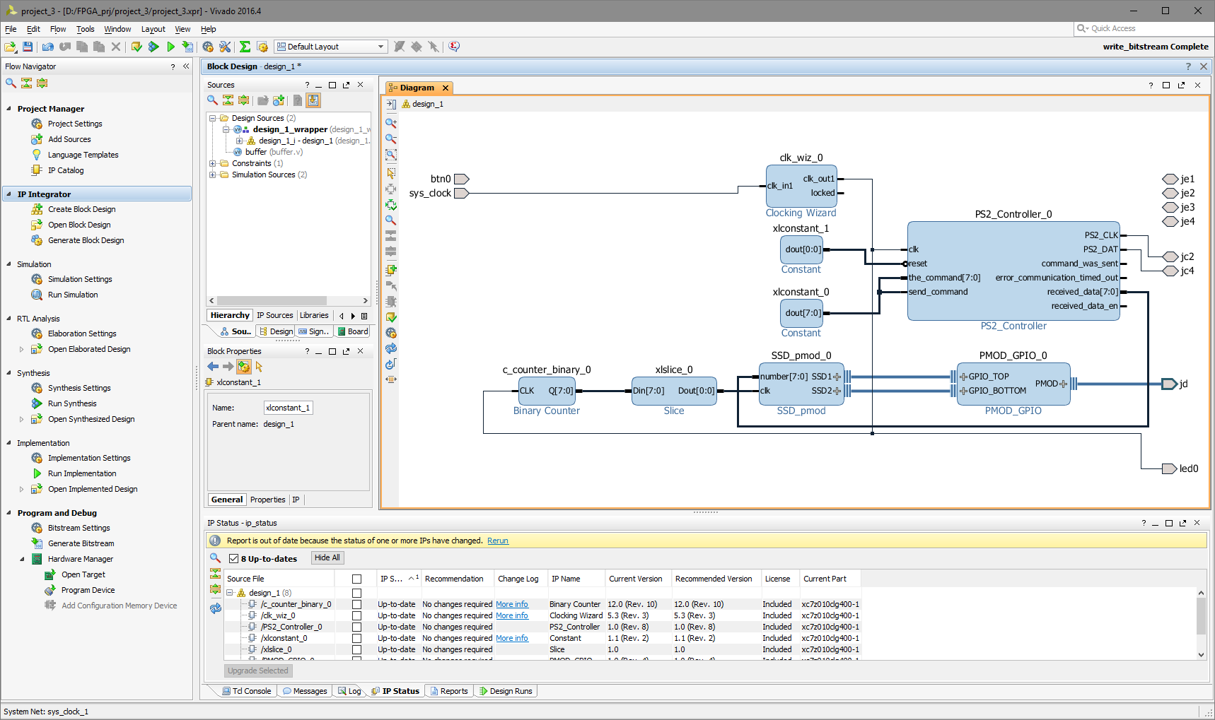
The following IPs were used here:
Clocking wizard Sync signal creation module. Designed to create sync signals (up to 6 pieces) with different frequency and duty cycle (in this case, one meander 100MHz). The system clock (125 MHz) is fed to the input. Uses the PLL resource, the output sync signals are distributed through the corresponding crystal resources. Standard Xilinx module.
Binary Counter. Custom divider, in this case 8-bit. Standard Xilinx module.
Slice. The bus divider, in this case, pulls out the high-order bit from the Binary Counter, thus forming a divisor by 256. The standard Xilinx module.
In general, such things cannot be done with the clock signal, you need to take another exit from the Clocking Wizard and correctly configure Clock Domain Crossing. But in this case, for the operation of SSD_pmod, any frequency from hundreds of hertz to hundreds of kilohertz, which is not synchronized with anything at all, is suitable.
SSD_pmod. A module that displays a byte in hexadecimal form on a two-digit seven-segment indicator Digilent PMOD-SSD. Byte is fed to the input of the module. The source code module is posted on GitHub.
PMOD_GPIO. A module that describes how to work with signals in the PMOD connectors. Depending on the type of module connected to the connector, different protocols are used - GPIO, SPI, I2C, UART. I took the module written by Digilent to support my PMOD, and slightly changed it. The source code module is posted on GitHub.
Constant module . This is just a constant of 0 or 1. In this case, we don’t use the transfer in the direction of the keyboard, so the send_command and the_command inputs are 0, and the reset input is 1 (in the final project we will have a full reset circuit).
Finally PS2_controller, the module we created in the previous step. Do not forget to specify the path to it in the project properties so that it can be added.
We use the following external connections:
sys_clock A clock signal 125MHz from an external oscillator on the board (pin L16). Used to run PLL.
PMOD_C A keyboard is connected to port C, bits JC2 (W15) and JC4 (T10) are used
PMOD_D A seven-segment indicator is connected to port D, all 8 bits are used.
We save the block design, generate a Verilog wrapper (Generate HDL Wrapper ...), compile the project (Generate Bitstream), upload it via JTAG to the board (Open Hardware Manager, Open Target, Program Device). Now when you press the buttons on the keyboard, their scan codes will be displayed on a seven-segment display:
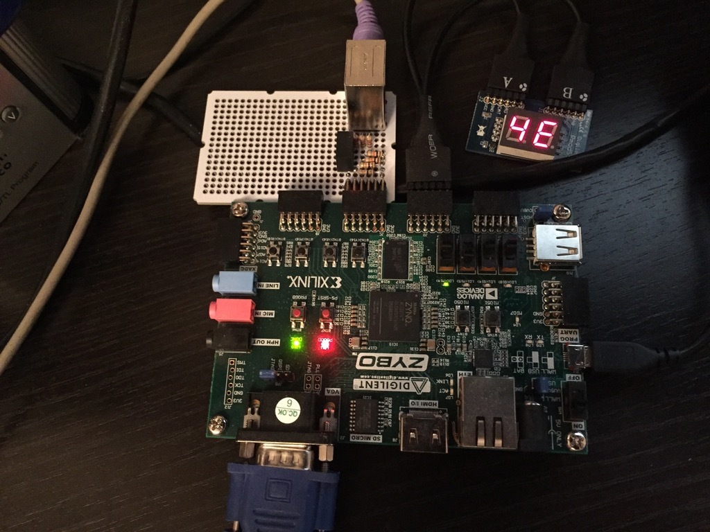
8'h4E is '-'
Links
For those who want to try all this on hardware, all the sources are posted on Github:
→ Wrapper to work with Git from Vivado
In addition, you will need to install:
→ Description of interfaces and boards of Digilent, including Zybo
→ Once and twice - auxiliary modules for outputting hexadecimal numbers to a seven-segment indicator
→ PS2 keyboard controller
→ The module in which it all connects together
To install the module, you need to download it from Github and run the .tcl file in the root from under Vivado
Source: https://habr.com/ru/post/327996/
All Articles