How laser roulette works: reverse engineering
 Earlier in my article I talked about how phase laser range finders are arranged. Now it's time to figure out how household laser roulettes work. Understanding is not just looking at what's inside, but completely restoring the entire circuit and writing your own program for the microcontroller.
The principle of laser roulette
Most laser roulettes use a phase rather than pulsed (time-of-flight, TOF) method for measuring distance.
For the integrity of this article, I will quote a part of the theory from my previous article:
In the phase method, in contrast to the pulse method, the laser operates continuously, but its radiation is amplitude modulated by a signal of a certain frequency (usually it is less than 500 MHz). I note that the laser wavelength remains unchanged (it is in the range of 500 - 1100 nm).
The radiation reflected from the object is received by the photodetector, and its phase is compared with the phase of the reference signal - from the laser. The presence of a delay in the propagation of a wave creates a phase shift, which is measured by a rangefinder.
')
The distance is determined by the formula:D = f r a c c 2 f c d o t f r a c v a r p h i 2 p i
Where c is the speed of light, f is the laser modulation frequency, ph is the phase shift.
This formula is valid only if the distance to the object is less than half the wavelength of the modulating signal, which is equal to c / 2f.
If the modulation frequency is 10 MHz, then the measured distance can be up to 15 meters, and as the distance changes from 0 to 15 meters, the phase difference will change from 0 to 360 degrees. A change in the phase shift of 1 degree in this case corresponds to a movement of the object by about 4 cm.
When this distance is exceeded, ambiguity occurs - it is impossible to determine how many periods of the wave fit into the measured distance. To resolve the ambiguity, the modulation frequency of the laser is switched, after which the resulting system of equations is solved.
The simplest case is the use of two frequencies, the distance to the object is approximately determined at a low (but the maximum distance is still limited), the distance is determined at a high with the required accuracy - with the same accuracy of phase shift measurement, when using high frequency the distance measurement accuracy will be much higher.
Since there are relatively simple ways to measure the phase shift with high accuracy, the accuracy of the distance measurement in such rangefinders can be up to 0.5 mm. It is the phase principle that is used in range finders that require high measurement accuracy - geodesic range finders, laser tape measures, scanning range finders mounted on robots.
However, the method also has drawbacks - the radiation power of a constantly operating laser is noticeably less than that of a pulsed laser, which does not allow the use of phase rangefinders for measuring large distances. In addition, the phase measurement with the required accuracy can take some time, which limits the speed of the device.
As I mentioned above, in order to increase the accuracy, it is necessary to increase the modulation frequency of the laser radiation. However, it is quite difficult to measure the phase difference between two high-frequency signals. Therefore, heterodyne signal conversion is often used in phase range finders. The structural diagram of such a rangefinder is shown below. The laser tape measure that I am considering is exactly that.
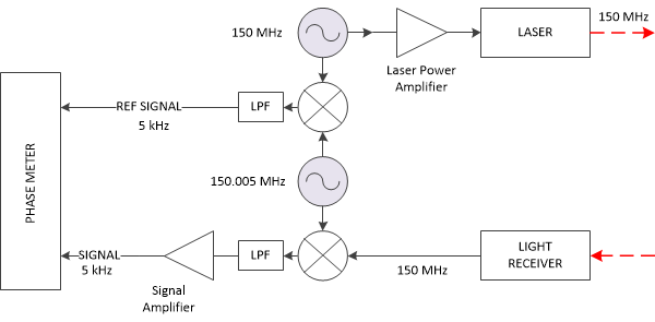
The rangefinder consists of two high-frequency oscillator, forming two signals that are close in frequency. The signal from one of them is fed to the laser, the signal from the other (local oscillator) is multiplied with the signal received by the photodetector. The resulting signal is fed to a filter that passes only low frequencies (LPF), so that only the signal of the difference frequency remains at the filter output. This signal has a very small amplitude, and it has to be amplified before being fed to the microcontroller. It is worth noting that making a low-frequency amplifier with a large gain is much easier than a high-frequency one, which is also an advantage of the heterodyne circuit.
Since it is the phase difference of the signals that is measured in the phase range finder, the design needs another signal, the reference one. It is obtained by multiplying the signals from both generators. Both of the resulting low-frequency signals are processed by a rangefinder microcontroller, which calculates the phase difference between them.
Separately, it is worth mentioning that avalanche photodiodes (APD) are used as photodetectors in most laser range finders. They have their own internal signal amplification, which reduces the requirements for amplifying nodes of the rangefinder. The gain of such photodiodes is nonlinearly dependent on the supply voltage. Thus, if the APD supply voltage is modulated by a local oscillator signal, the signals are mixed (multiplied) right in the photodiode itself. This allows you to simplify the design of the rangefinder, and reduce the influence of noise.
At the same time, avalanche photodiodes have many disadvantages. These include:
- The supply voltage must be high enough - a hundred volts and above.
- Strong dependence of parameters on temperature.
- Enough high cost (compared to other photodiodes).
Reverse Engineering Laser Roulette
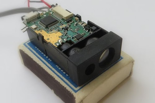
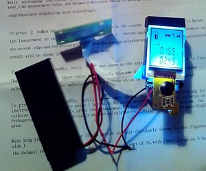 As an experimental sample, I used the “50M DIY Rangefinder” kit found on Aliexpress’s open spaces (on the right is a photo of the included roulette). As I understand it, this set is the insides of the X-40 laser roulette (now you can find it for sale for $ 20). I chose this set only because his photographs showed the electronics of the device. According to my information, the circuitry of this roulette is very close to the circuitry of the U-NIT UT390B + roulette, and other Chinese laser roulettes and laser rangefinder modules.
During the tests I was able to check the work of the roulette only 10 meters away. It worked with great difficulty, the measurement time was more than 5 seconds. I suspect that even the distance of 20 meters could not be measured, let alone the 50 m declared by the manufacturer.
What is the design of such a roulette?

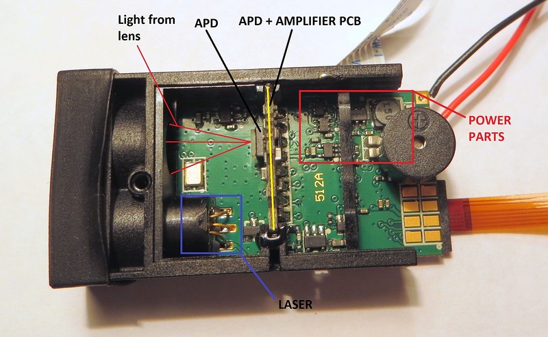
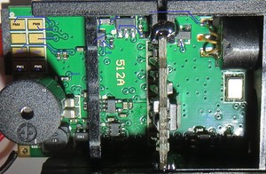
As you can see from the photos, it is quite simple. Structurally, the tape measure consists of a laser rangefinder unit, an indicator and a board with buttons. Obviously, the most interesting is the range finder unit. This is how it looks close:
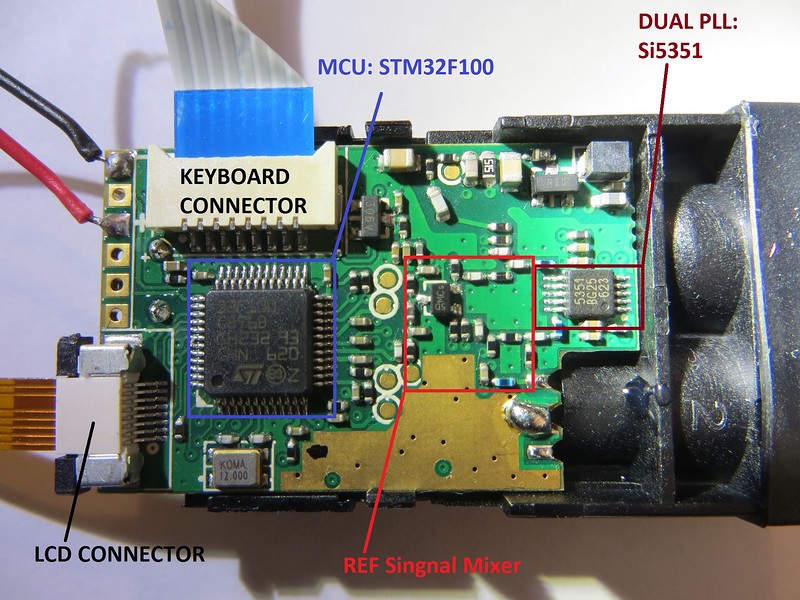
On the upper side of the board there are two main chips of the rangefinder - the STM32F100C8T6 microcontroller and the dual PLL generator Si5351. This chip is capable of generating two signals with frequencies up to 200 MHz. It forms the signal for modulating the laser and the local oscillator signal. Also on this side of the board is the mixer and the reference filter (REF) signal and part of the details of the high-voltage source assembly for the APD (at the top of the photo).
This is the bottom side of the rangefinder unit:
From the photo it may not be clear, but in fact here you can see two printed circuit boards - the second one is very small and fixed vertically. This photo clearly shows the conclusions of the laser diode, a small speaker (he constantly squeaked while working, so I later dropped it). In addition, there are components that form the supply voltage of the tape.
A small avalanche photodiode with a built-in interference filter and a received signal amplifier is located on a small scarf. This is how the board looks like:
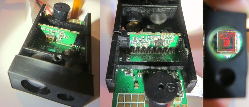
The photo on the right shows a view of an avalanche photodiode through a lens-lens of a tape measure.
The next stage is the restoration of the roulette scheme. The board is rather small and not very complicated, although multi-layered, so the process of restoring the circuit took not very long.
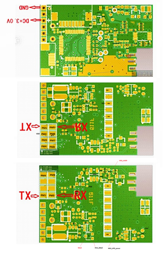
Photo boards with signed components:
In one of the Chinese online stores I managed to find a picture with the image of the PCB of the laser rangefinder module (version 511F), which was very close in design with my board (version 512A). Image resolution is rather low, but it shows the location of the conductors and vias under the microcircuits. Later I signed the component numbers on it and allocated the conductors:
Unfortunately, it was not possible to determine their names by marking the parts of the SMD components. The ratings of most capacitors can not be determined without watering them from the board. The ratings of the resistors I measured with a multimeter, so that they can be determined inaccurately.
As a result of the research, I got this structural scheme of the roulette:

I broke the electrical circuit into several sheets:

Scheme 1. The microcontroller, the power node and some simple circuits.
Everything is quite simple here - here the STM32 microcontroller is shown, some elements of its binding, a speaker, a keyboard, some low-pass filters. It also shows the step-up DC-DC voltage converter (chip DA1), which forms the voltage supply for the tape measure.
The tape measure is designed to work from 2 batteries, the voltage of which may vary during operation. The specified converter forms a constant voltage of 3.5 V from the input voltage VBAT (a somewhat unusual value). To turn the roulette's power on and off, use a node assembled on a transistor assembly DA2. When you press the S1 button, it turns on DC-DC, after which the MCU_power starts holding DC-DC on with a signal on the MCU_power line.
During one of the measurements, I accidentally burned the microcircuit of this DC-DC converter (the multimeter probe jumped off, and closed its legs). Since I could not determine the name of the microcircuit, I had to evaporate it, and supply 3.5 V to the roulette from an external voltage source.
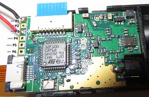
Below on the edge of the board there are 8 rectangular pads that can be used as debug or test ones. I marked them on the PMx chart. From the diagram it is clear that all of them are connected to the conclusions of the microcontroller. Among them are the UART lines. Native firmware does not conduct any activity on these lines, the TX line, judging by the oscilloscope, is configured at the input.
There are also 6 contact holes on the edge of the board. In the diagram, they are marked “Px”. They displayed roulette power lines and STM32 programming lines.
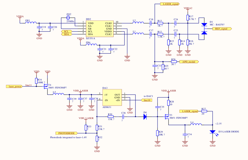
Scheme 2. Node PLL generator, and the control unit of the laser diode.
The Si5351 PLL chip generates a rectangular signal, therefore, to remove unnecessary harmonics, the signals from the PLL output are fed to two identical band-pass filters. It also shows the signal mixer, assembled on the diode D1 - the signal from it is used as a reference when measuring the phase difference.
As can be seen from the diagram, one of the signals with PLL (“LASER_signal”) is output to the laser diode D3 without any transformations. On the other hand, the brightness of the laser (which is determined by the amount of current flowing through it) is stabilized using an analog node assembled on a DA3 chip and its surrounding components. This node receives the real brightness level of the laser from the photodiode built into the laser (it is not shown in the diagram). With the help of the laser_power line, the microcontroller can completely turn off the laser, and with the help of the line 10 line connected to the microcontroller's DAC, adjust the laser brightness. The oscilloscope study showed that the tape measure constantly keeps the value 1.4 V on this line, and it does not change under any conditions.

Scheme 3. APD power node and signal amplifier with APD.
On the left there is a linear voltage source, which forms the supply voltage for the photodiode amplifier (DA5). This microcircuit generates a voltage of 3.3 V, so the voltage at its input must be above 3.3 V. As far as I understand, this is the reason that the rest of the circuit is powered from 3.5 V.
Below is a step-up DC-DC converter assembled on a DA4 chip that generates a high voltage (> 80 V) for an avalanche photodiode. The microcontroller can change the value of this voltage using the line "MCU_APD_CTRL" connected to the DAC of the controller. The name of the chip DA4 I could not install, so I had to experimentally determine how the voltage on the APD depends on the level of the control signal. This dependence turns out to be some kind of strange, as the magnitude of the control signal increases, the output voltage drops. In further experiments, I used several constant DAC values, for which I knew the corresponding output voltages.
Diagram 3 on the right shows a diagram of a small printed circuit board. Lines M1-M8 show the pads connecting both boards. D6 diode is an avalanche photodiode (APD). It is not marked in any way, so it is impossible to determine its name and characteristics. I can only say that it has an LCC3 case.
A high constant voltage is applied to the APD cathode via the M8 line. It can also be seen that through the capacitor C41 along the line “APD_modul” a high-frequency signal from the PLL is mixed in with it. Thus, on the APD, the optical signal and the signal “APD_modul” having different frequencies are mixed. As a result, a low-frequency signal appears on the APD output, which is allocated by a bandpass filter (components C55, R41, R42, R44, C58, C59).
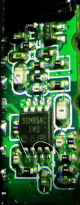
Further, the low-frequency signal is amplified by an operational amplifier DA6B (SGM8542). The signal from the output of DA6B is transmitted to the ADC of the microcontroller via the M2 line. Also, this signal is additionally amplified by the transistor T6 and transmitted to the microcontroller via the M1 line.
Such a step gain is needed due to the fact that the input level varies over very wide limits.
In addition, a thermistor R58 is installed next to the APD, which allows to determine the temperature of the APD. As I said, the APD parameters are strongly temperature dependent, and a thermistor is needed to programmatically compensate for this dependence. In the process, the APD heats up, and even this changes its characteristics. For example, at room temperature, due to self-heating, the gain of the photodiode drops by more than 2 times.
In the case where the received signal level is not enough, the microcontroller increases the voltage on the APD, thus increasing the gain. During the test of the roulette with native firmware, I found that there are only two levels of output voltage - 80 and 93 V. However, at that time I did not realize that these levels can depend on the temperature of the APD, and did not check if the roulette changes any control signals when heated.
The photographs of the board show that there are monitoring sites on it. I marked them on the diagram and the board: “TPx”. Among them are:
- TP3, TP4 - low-frequency signal from the photodiode amplifier. This signal carries information about the distance to the object. Using an oscilloscope, you can see that the signal has a frequency of 5 kHz, and contains a constant component.
- TP1 is the reference signal. It also has a frequency of 5 kHz and contains a constant component. The amplitude of this signal is quite small - about 100 mV.
- TP5 - high voltage avalanche photodiode.
Programming
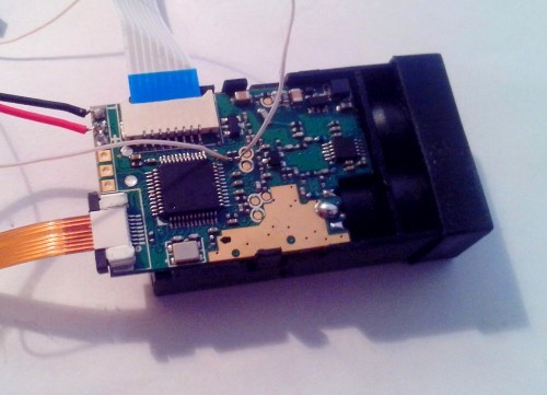
Before trying to do something with the controller's native firmware, I decided to remove the exchange between the STM32 and the PLL using the logic analyzer, which takes place on the I2C bus. For this, I soldered the wires to the bus pull-up resistors:
I managed to intercept the exchange between the mentioned chips without any problems and decode the data in the transmitted packages:
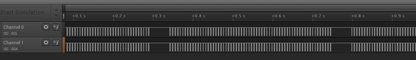
Analysis of the results showed that the controller always only writes information to the PLL, and does not read anything. With a good signal level, one measurement cycle takes about 0.4 seconds; with a bad signal level, measurements take much longer.
It can be seen that the microcontroller transmits to the PLL fairly large parcels with a period of about 5 ms.
Since there was a lot of data, I wrote a special program in Python to analyze them. The program determined and counted the packages, determined the size of the packages, the time between them. In addition, the program displays the names of the PLL registers into which the bytes are transferred.
As it turned out, every 5 ms STM32 completely overwrites the main PLL registers (packet length is 51 bytes), with the result that the PLL changes both frequencies. No initialization of the PLL roulette does not hold - that is, the packets of transmitted data carry the full configuration of the PLL. With a good signal level, the measurement cycle consists of 64 data transmissions.
Next, I added to the program the calculation of the frequency of the data transmitted in the packets. It turned out that during the measurement process, the tape measure uses four laser modulation frequencies:
- 162.0 MHz
- 189.0 MHz
- 192.75 MHz
- 193.5 MHz
The frequency of the local oscillator (the second PLL output) always has a frequency that is 5 kHz less than the modulation frequency of the laser.
Apparently, 4 cycles of switching frequencies (5 ms each) allow for a single determination of the distance. Thus, after 64 cycles, the tape measure performs 16 distance measurements, after which it averages and filters the results, thereby improving the measurement accuracy.
Next, I began to write my program for the roulette microcontroller.
After connecting the programmer to the roulette, the computer did not detect its microcontroller. As far as I understand, it means that SWD interface is disabled by software in native firmware. I bypassed this problem by connecting the NRST programmer line to the roulette and selecting the “Connect under reset” mode in the ST-LINK Utility settings. After that, the computer found the controller, but, as expected, the native firmware was protected from reading. In order to write a program to the controller, the controller's flash memory had to be erased.
First of all, in my program, I implemented switching on the power of the analog part of the rangefinder, turning on the laser and setting its current, turning on the power supply voltage APD. After I made sure that all the voltages were normal, it was possible to experiment with PLL. For the test, I simply implemented a record in the PLL of the data that I previously received from the roulette.
As a result, after launching my program, I discovered that a signal with a frequency of 5 kHz appeared at the control points, the amplitude of which clearly depended on the type of object to which the laser was shining. This meant that all analog electronics was working properly.
After that, I added to the program the capture of an analog signal using an ADC. It is worth noting that in order to measure the phase difference of signals, the microcontroller must capture the levels of the main and reference signals simultaneously or with a constant delay. In STM32F100, the last option can be implemented using the ADC scanning mode. At the same time, it is logical to capture data from the ADC using DMA, and in order for the data to be captured at a given sampling rate, the ADC conversion must be triggered by a signal from one of the timers.
As a result of the experiments, I settled on the following capture parameters:
- ADC sampling rate - 50 kHz,
- The number of samples - 250.
- The total signal capture time is 5 ms.
- The captured data is transmitted by the controller program to the PC via UART.
To handle the captured data, I wrote a small program in C #:
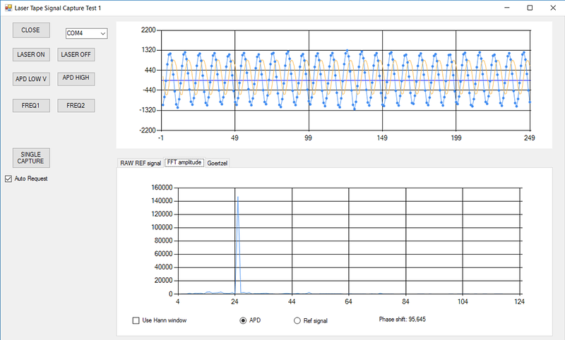
The blue graph is the received signal, the orange graph is the reference signal (its amplitude in this graph has been increased by 20 times).
The graph below shows the result of the received signal FFT.
Using the FFT, you can determine the phase of the signal - you need to calculate the phase spectrum of the signal, and choose from it the value of the phase at the point corresponding to 5 kHz. I note that I tried to display the phase spectrum on the screen, but it looks noisy, so I refused this.
At the same time, in reality, two signals arrive at the microcontroller — the main and the reference. This means that it is necessary to calculate the phase of each signal at a frequency of 5 kHz using FFT, and then subtract the other from one result. The result is the desired phase difference, which is used to calculate the distance. My program displays this value under the spectrum graph.
Obviously, the use of FFT is not the most appropriate method for determining the phase of a signal at a single frequency. Instead, I decided to use the Görtsel algorithm . I will quote Wikipedia:
The Goertzel algorithm (Eng. Goertzel algorithm) is a special implementation of the discrete Fourier transform (DFT) in the form of a recursive filter. ... Unlike the fast Fourier transform that calculates all the frequency components of the DFT, the Görtzel algorithm effectively calculates the value of one frequency component.
This algorithm is very simple to implement. Like the FFT, it can return a complex result, so you can calculate the phase of the signal. In the case of using this algorithm, it is also necessary to calculate the phases of the main and reference signals, and then calculate their difference.
The same PC program allows you to calculate the phase difference and signal amplitude using the Goertzel algorithm. Experimental results showed that, with a good signal level, the accuracy of measuring the phase difference can reach up to 0.4 degrees (RMS in 20 measurements).
At the next stage, I wrote a program for the microcontroller, which itself calculated the phase difference of signals for three different modulation frequencies (using the Goertzel algorithm), and transmitted the result to a PC. Why three frequencies were used, I will explain later. Due to the fact that calculations are made on the microcontroller itself, there is no need to transfer a large amount of data on the UART, which significantly increases the measurement speed.
For the PC, a program was written that allowed to capture the received data and log them.
It was at this stage that I noticed a strong influence of the avalanche photodiode temperature on the results of measuring the phase difference. In addition, I noticed that the amplitude of the received light signal also affects the result. In addition, when the APD supply voltage changes, the above dependences clearly change.
Frankly speaking, in the process of research, I realized that the task of determining the influence of several factors at once (supply voltage, amplitude of the light signal, temperature) on the phase difference is quite complex, and, ideally, requires a large and lengthy study. For such a study, a climate chamber is needed to simulate various working temperatures and a set of light filters to study the effect of the signal level on the result. You need to make a special stand that can automatically change the level of the light signal. Research is complicated by the fact that as the temperature decreases, the APD gain increases, and to such an extent that the APD enters saturation mode — the signal at its output turns from sinusoidal to rectangular or disappears altogether.
I did not have such equipment, so I had to limit myself to simpler means. I conducted research on the range finder operation only with two operating voltages of an avalanche photodiode (Uapd) of 82 V and 98 V. All studies were carried out at a modulation frequency of a 160 MHz laser.
In my research, I believed that changes in the amplitude of the light signal and temperature independently of each other affect the results of measuring the phase difference.
To change the amplitude of the received light signal, I used a special movable table with an attached flap that could overlap the lens of the photodiode:

With the change in temperature, everything was more complicated. First of all, as I mentioned earlier, the APD had a noticeable self-heating effect, which was well monitored by a thermal sensor. To cool the roulette, I covered it with a foam box with a fan installed in it, and installed a cold water tank on top. In addition, I tried to cool the roulette on the balcony (there was about 10 ° C). Judging by the signal level from the thermal sensor, both methods gave approximately the same APD temperature. With heating everything is easier - I heated the tape measure with a stream of hot air. For this, I used a resistor attached to the cooler - it was so possible to regulate the air temperature.
I did not have any information about the thermoresistor installed in the roulette, so I never recounted the results of converting the ADC to degrees. With increasing temperature, the voltage level on the ADC fell.
The result is the following results:
- With increasing Uapd (that is, with increasing gain), the sensitivity of the APD to temperature changes and changes in the signal level increases noticeably.
- When the amplitude of the light signal decreases, a small phase shift appears - approximately +2 degrees when the amplitude changes from maximum to minimum.
- As the APD cools, a positive phase shift appears.
For a voltage of 98 V, such a dependence of the phase shift on temperature (in units of ADC) was obtained:
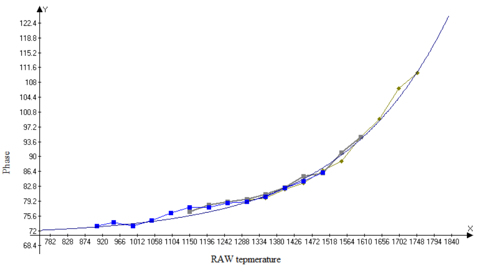
It can be seen that with a change in temperature (approximately from 15 to 40 degrees), the phase difference changes by more than 30 degrees.
For a voltage of 82 V, this dependence turned out to be almost linear (at least in the temperature range where I conducted the measurements).
As a result, I received two graphs for two Uapd, which showed a relationship between temperature and phase shift. Using these graphs, I determined two mathematical functions that I used in the microcontroller to correct the value of the phase difference. Thus, I was able to get rid of the influence of changes in external factors on the accuracy of measurements.
The next step is to determine the distance to the object using the three phase differences obtained. For starters, I decided to do it on a PC.
What is the problem? As I mentioned earlier, if the modulation frequency is high enough, then at a certain distance from the range finder, an attempt to determine the distance causes ambiguity. In this case, to accurately determine the distance to the object, you need to know not only the phase difference, but also the number of integer signal phases (N) that fit into this distance.
The distance in the result is determined by the formula:
D = 12 (N⋅λ+φ⋅λ2 π )
From the analysis of the factory roulette program, it can be seen that the modulation frequencies lie in the range of 160-195 MHz. It is likely that the circuitry of the roulette will not allow modulating the laser radiation with a lower frequency (I did not check it). This means that the method of determining the distance to an object from the phase difference in the roulette should be more difficult than simply switching between high and low modulation frequencies.
It is worth noting that due to the fact that the modulation frequencies are different, then the number of the entire signal phases in some cases may have a common N value, and in others - not (N1, N2 ...).
I know only two options for solving this problem.
The first option is a simple enumeration of the values of N and the corresponding distances for each modulation frequency used.
In the course of such sorting, the values of N are searched for, which give the distances that are the most coincident with each other (complete coincidence may not be obtained due to errors in measuring the phase difference).
The disadvantage of this method is that it requires many operations and is quite sensitive to phase measurement errors.
The second option is to use the effect of beats of signals with similar modulation frequencies.
Let the rangefinder use two modulation frequencies of the signal with wavelengthsλ 1 and λ 2 , having rather close values. It can be assumed that at the distance to the object the number of integer periods N1 and N2 are equal to each other and equal to some value N.In this case, the following system of equations is obtained:
{ D = 12 (N⋅λ1+ φ 1 ⋅ λ 12 π )D=12 (N⋅λ2+ φ 2 ⋅ λ 22 π )
From it you can derive the value of N:
N = λ 2 ⋅ φ 22 π +λ1⋅φ 12 πλ 1 - λ 2
Having obtained the value of N, one can calculate the distance to the object.
The maximum distance at which the above statement is fulfilled is defined by the formula:
D m a x = 12 ⋅λ 1 ⋅λ 2| λ 2 - λ 1 |
This formula shows that the closer the wavelengths of the signals are to each other, the greater the maximum distance.
At the same time, even at the specified distance in some cases this statement (N1 = N2) will not be fulfilled.
I will give a simple example.
Let be λ 1 = 1.55 m and λ 2 = 1.5 m .
In this case D m a x = 11.6 m .
But if in this case the path that the light passes is 1.53 m, then it turns out that for the first wavelength N1 = 0, and for the second one N2 = 1.
As a result of the calculation, the value of N is negative.
You can fight this effect using the knowledge that
λ 1 > λ 2 .
In this case, you can modify the system of equations:
{ D = 12 (N1⋅λ1+ φ 1 ⋅ λ 12 π )D=12((N1+1)⋅λ2+φ2⋅λ22π)
Using this system of equations, you can find N1.
The application of this method has a certain feature - the closer to each other the wavelengths of the modulation signals, the greater the effect of measurement errors of the phase difference on the result. Due to the presence of such errors, the value of N may not be calculated accurately enough, but at least it turns out to be close to the real value.
When determining the real distance to the object, it is necessary to perform a zero calibration. It is done quite simply - at a certain distance from the roulette, which will be taken as “0”, a well-reflecting object is installed. After that, the program should save the measured values of the phase difference for each of the modulation frequencies. In further work, you need to subtract these values from the corresponding values of the phase differences.
In my distance determination algorithm, I decided to use three modulation frequencies: 162.5 MHz, 191.5 MHz, 193.5 MHz - according to the results of experiments, this was the most suitable number of frequencies.
My algorithm for determining the distance consists of three stages:
- Check whether phase differences have fallen into the zone of "zero" distance. In the area close to zero calibration, due to measurement errors, the value of the phase difference can “jump” - from 0 degrees to 359 degrees, which leads to large errors when measuring the distance. Therefore, when it is found that all three phase differences at the same time turned out to be close to zero, we can assume that the measured distance is close to zero, and thus to abandon the calculation of the values of N.
- 191.5 193.5 . , : Dmax=37.5 , . ( ).
- 162.5 191.5 .
, N . .
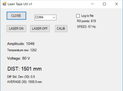
As a result, I got this PC program:
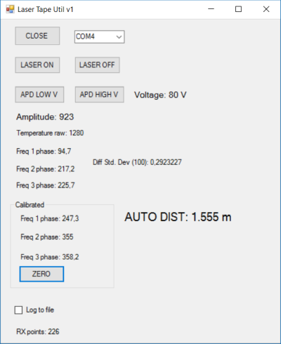
This program allows you to display data transmitted by a tape measure - signal amplitude, APD voltage, temperature in ADC units, signal phase difference values for three frequencies and the distance to the object calculated from them.
Zero calibration is performed in the program itself when pressing the "ZERO" button.
For a standalone laser rangefinder, it is important that the gain of the signal can be changed, since the signal level can vary greatly as the distance and reflectance change. In my microcontroller program, I implemented a gain change by switching between two APD supply voltages - 82 V and 98 V. When switching the voltage, the gain level changed about 10 times.
I did not implement switching between two ADC channels - “MCU_signal_high”, “MCU_signal_low” - the microcontroller program always uses the signal only from the “MCU_signal_high” channel.
The next step, the final one, consists in transferring the distance calculation algorithm to the microcontroller. Due to the fact that the algorithm was already tested on a PC, it was not difficult. In addition, the program of the microcontroller had to add the ability to perform zero calibration. The microcontroller stores this calibration data in Flash memory.
I implemented two different versions of the microcontroller firmware, differing in the principle of signal capture. In one of them, a simpler one, the microcontroller does nothing during data capture from the ADC. The second firmware is more complicated, in it the data from the ADC are simultaneously recorded into one of the arrays using DMA, and at the same time, the data already captured earlier are processed using the Goertzel algorithm. Due to this, the measurement speed increases almost 2 times compared to a simple version of the firmware.
The result of the calculations is sent by the microcontroller to the computer via the UART.
For the convenience of analyzing the results, I wrote another small program for the PC:
results
As a result, I was able to find out exactly how the laser roulette electronics work, and write my own open source firmware for it.
For me, in the process of writing the firmware, the most important thing was to achieve the maximum measurement speed. Unfortunately, an increase in the measurement speed significantly affects the accuracy of measurements, so a compromise is required. For example, the code at the end of this article provides 60 measurements per second, and the accuracy is about 5-10 mm.
If you reduce the number of captured signal values, you can increase the speed of measurements. I received 100 measurements per second, but the effect of noise increased significantly.
Of course, external conditions, such as the distance to the object and the surface reflection coefficient, strongly influence the signal-to-noise ratio and, consequently, the measurement accuracy. Unfortunately, if the light signal is too low, even an increase in the APD gain does not help much - with an increase in the gain, the noise level also increases.
During the experiments, I noticed that the external illumination of the avalanche photodiode also significantly increases the level of interference. In the module that I had, all the electronics are open, so that in order to reduce interference it is necessary to cover it with something opaque.
Another feature noted is that due to the fact that the optical axes of the laser and the lens of the photodiode do not coincide, the signal level drops significantly at close distances (<0.7 m) .
In principle, even in this form, the roulette electronics can be used in some project, for example, as a distance sensor for a robot.
Video showing the work of roulette:
Finally: what roulette can you still find?
Here I want to talk about the designs of other laser roulettes, about which you can find information in the network.
- - BOSCH DLE50.
— PLL CF325, , -. ( ) , , , — «».
— ATmega169P.
— , , « », . , , ( ). .
. - UT390B.
- UART , . Arduino .
.
, , , .
— STM32F103C8. PLL: CKEL925 ( ). - But no one has yet been able to figure out the protocol of the UT390B + roulette. Circuit design of this tape is different from its old version .
It is even closer to the circuitry of my roulette - it uses the STM32F030CBT6 microcontroller and the PLL Si5351.
If you look at the photos, you will notice that there are two lasers installed in the roulette.
Apparently, two roulette lasers now are not uncommon. Here in this device description another roulette is mentioned that one of the lasers has visible radiation, and serves only for “target designation”, and the second laser is infrared, and is used to measure the distance. Interestingly, in this case both the laser and the photodiode use the same lens. - Another roulette with an unknown protocol - BOSCH PLR 15.
Enthusiasts have already tried to deal with its protocol, but so far no one has succeeded.
Previously, I also tried to find out how this roulette works, and even partially restored the scheme of this roulette.
The microcontroller used in this roulette is STM32F051R6. But there are simply no other integrated circuits in it!
But the photodetector is used here is very unusual, I have never met even the mention of such devices: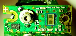
Apparently, it is a system on a chip, and contains two photodiodes (measuring and reference channels), photodiode amplifiers, digital control electronics and ADC. The laser modulation signal also comes from it. The photodetector itself is connected to the microcontroller via SPI.
I tried to intercept data that goes through SPI - there are commands from the controller to the sensor and information packets from the sensor to the controller.
If you process these packets in Excel, then sinusoids are clearly visible (that is, a phase distance measurement method is used). This means that the microcontroller deals with signal processing in this roulette.
However, there is a lot of information on SPI, it was not possible to establish the frequencies at which the measurements are carried out, so even counting the distance from the tape is a rather problematic task. - Various Chinese modules.
Recently, a large number of laser rangefinder modules have appeared in Chinese online stores (of which can be found on the query “laser ranging module” and similar ones).
Among them, you can find modules that look exactly the same as mine, but they are sold at twice the price ($ 40). It seems that these are all the same insides of laser roulettes, but with modified firmware. Interestingly, among the various designs, I came across rangefinders with two identical PLL chips several times (apparently, these chips are not custom-made).
→ Project files
→ Instructions for connecting the laser rangefinder to the Arduino
Source: https://habr.com/ru/post/327642/
All Articles