Automated generation of circuit components from PDF files for Altium Designer
Despite the fact that Altium Designer comes with huge component libraries, there is still the need to create its own circuit components in it. This is especially true for large microcircuits with a large number of conclusions and output attributes. These can be FPGAs, microcontrollers, processors, memory chips, etc. Here I will introduce my technology for generating circuit components extracting information from PDF files.
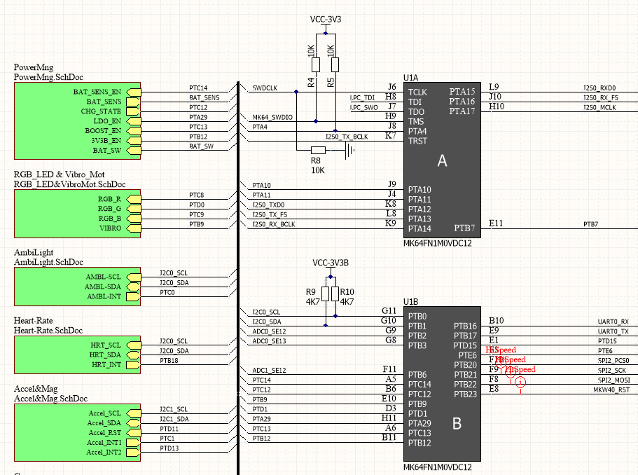
Take for example the datasheets for Kinetis microcontrollers, say the K66 series. It is not difficult to extract the circuit components of these microcontrollers from the numerous reference designs provided by the manufacturer. Fortunately, many of them are presented in the Altium Designer format. Download from here the archive "Hexiwear-Design-Files", we find a scheme there, and in it there is such a representation of the component:
(Click to enlarge)
Here the circuit component of the microcontroller is divided into several logical parts, since it was convenient for the author of the circuit. It only remains to envy the professionalism of the author, but usually such a miserly representation of the component makes it difficult to understand the operation of the circuit, and later also to find errors.
')
The microcontroller on its findings can support up to 7 alternative functions. Make a mistake in the designation of the function of at least one output and the board will have to be painfully tuned manually after production or even be thrown out if the case is BGA.
Therefore, we cannot borrow such a component. He also presented only for one body, and the body may be others, with a different pinout.
The situation with the components of microcontrollers found in third-party libraries is no better. They also do not indicate alternative functions.
I found a way to automate the generation of components from pdf datasheets.
Step 1
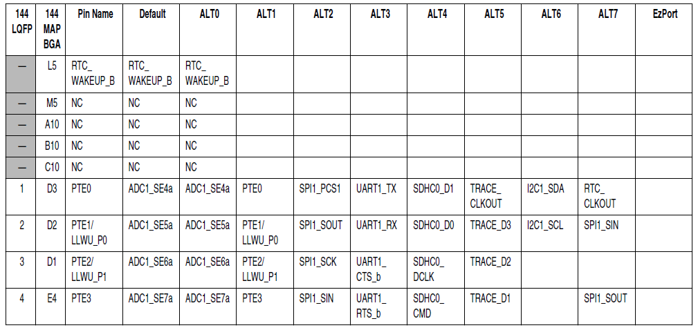
We define which tables in the datasheet represent pinout. For K66 it is presented in the form of such a table extending over several sheets.
(Click to enlarge)
This is a convenient presentation. In this table, the pin numbers and the names of all their functions are immediately summarized. But let's say, for the STM32 microcontrollers, the situation will be more complicated, there is a separate table of correspondence of the numbers of outputs to their basic names and a table of correspondence of the basic names and all alternative functions. This is also easily solved.
Step 2
From a PDF file we transfer tables to MS Excel. I used Adobe Acrobat for this. She has a free trial version.
We get a table in Excel of this type:

(Click to enlarge)
Step 3
I export a table from Excel to a text file where the table fields are separated by a tab (0x09).
Step 4
The table file we received is filled with all sorts of garbage inherited from formatting in a PDF file. This and unnecessary line breaks, and spaces, and other unnecessary characters.
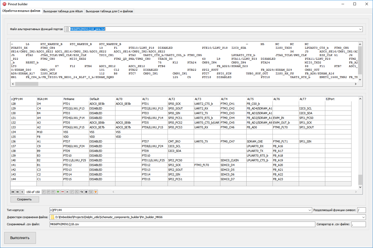
Therefore, I wrote a program in Delphi that imports a file and filters garbage.
(Click to enlarge)
The program window indicates the path to the file of alternative functions of the ports (this is our table exported from Excel), indicates the type of the microcircuit case (the list is filled in the Delphi program manually), indicates the directory and the file where the table will be converted into a format suitable for subsequent import into Altium ( it must be a file with a .csv extension). The separator for the csv file must be a comma. A symbol separating a function can be arbitrary, so that the enumerations of functions in the output description are conveniently read.
All correctly setting click "Run."
After successful execution, we will see in the tab “Output table for Altium” a table intended for processing by the Altium Designer script. The table is saved in the previously specified csv file.
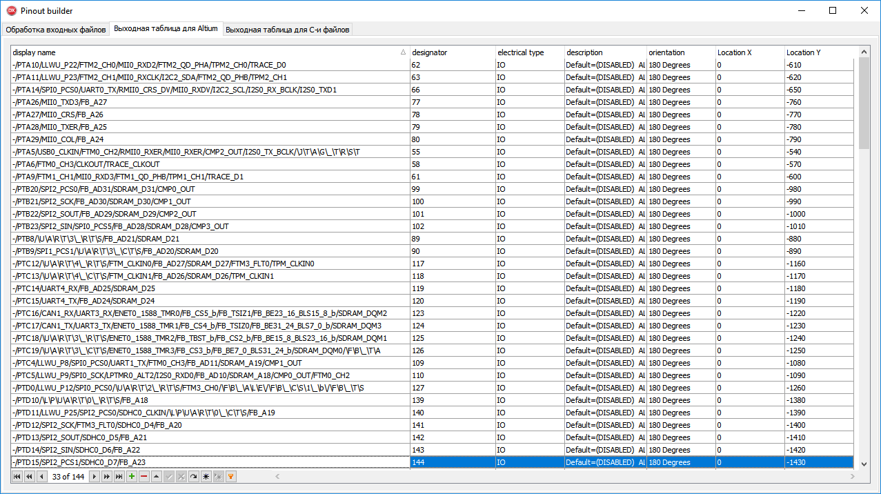
(Click to enlarge)
Step 5.
Open Altium Designer. Open the library of circuit components where we want to create a new component. Click the sequence DXP → Run Script. Specify the path to the script ImportPins.PRJSCR. This window appears:
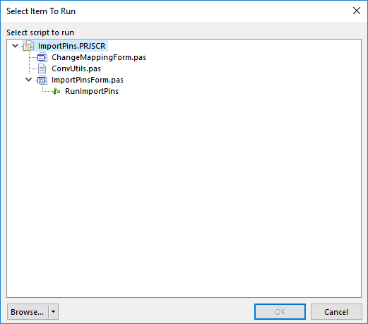
(Click to enlarge) .
In it we click RunImportPins. In the dialog that appears, specify the path to our csv file and click Update Mapping. We get a window with the following content.

We click Execute and in the editor window of the circuit component we get an image of all outputs with the assigned names and numbers:
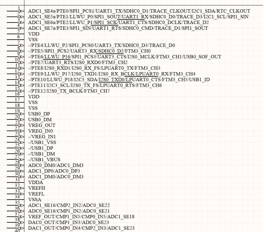
(Click to enlarge)
Everything! The work is done.
It may seem that this is a bit different from what was expected from the promised automation. But in fact, the exact correspondence of numbers and names of conclusions is the most responsible and hard work in the development of circuit components.
Then you can quite quickly edit the length of the pins, arrange them across the field, draw the contours, divide into functional groups, etc. This is a routine light work that will not lead to fatal mistakes. Further, in the footprint editor, it is also easy to make an IC case using the available wizards. Since the case of the microcontroller is quite typical.
The project repository is here .
The Pin_builder_MK66 directory contains all the files for repeating steps and their results described in this article. There's also the source files of the converter to Delphi. In the Import_pins_Altium_script directory there is a script project for Altium Designer.
The file FunctionsMapping.xlsx contains the source table exported from the datasheet.
The csv file for conversion is called MK66FN2M0VLQ18.csv
Source: https://habr.com/ru/post/327628/
All Articles