Armor is strong and our tanks are fast.
Greetings to all lovers of heavy equipment. Today in the blog of the group of companies LANIT historical post. It is dedicated to the upcoming Victory Day.
While the world powers continue to compete in military equipment and demonstrate more sophisticated models of armored vehicles, I want to tell you a couple of stories from the Soviet tank building. Moreover, many modern models are nothing more than the latest modifications of the machines of the famous series.
In these stories I took either indirectly or directly and saw what difficulties designers and technologists had to overcome.
')
It will be in my story and about information technology, because it was IT at one time that helped correct serious manufacturing defects, over which a whole team of engineers struggled.
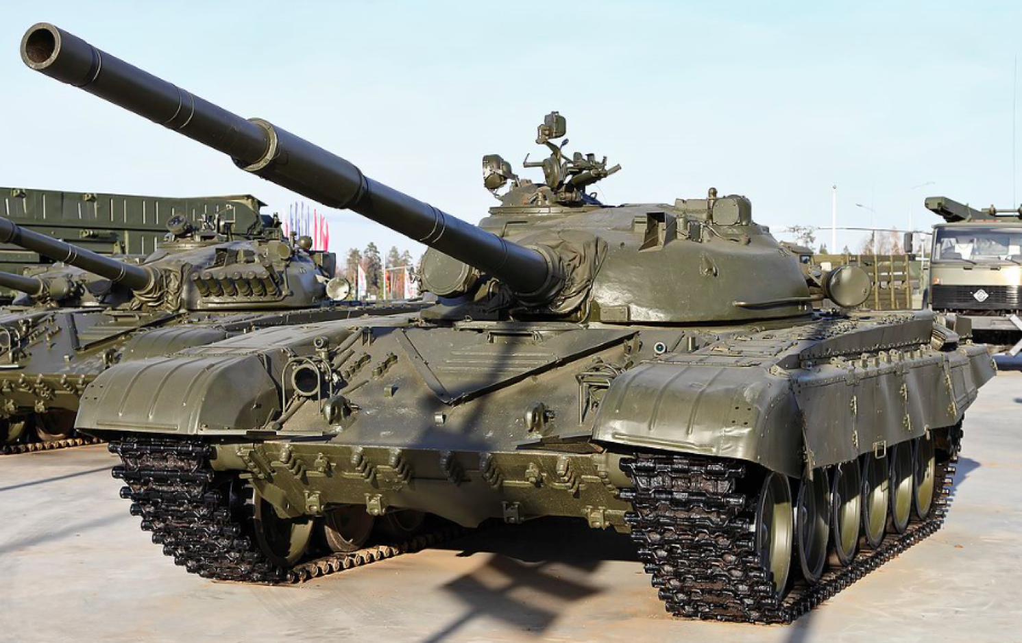
Figure 1. Source
Before you is a T-72 tank, produced at Uralvagonzavod. This is one of the first modifications of the tank of this series with a cast turret.
Cast turrets were used in the T-34 tank. This made it possible to obtain a component with a complex configuration, leaving only a few elements of its structure to be finished by machining. At the same time, it was a difficult cast. Its casting weight with profits and sprues reached 15 tons.
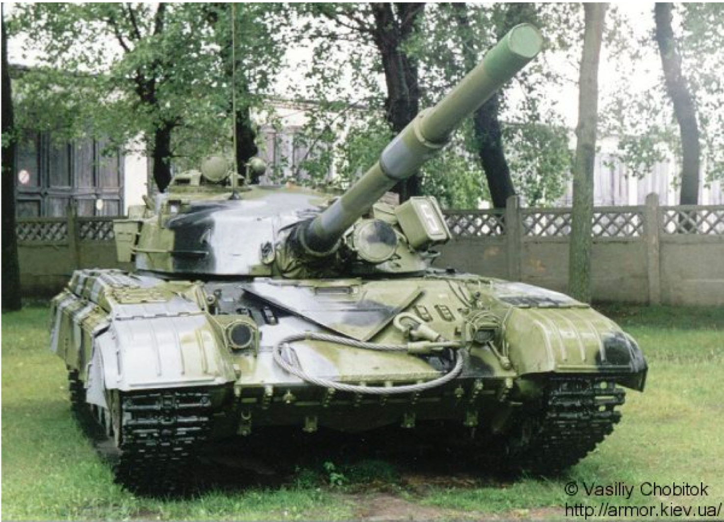
Figure 2. T-64 tank early releases of the Kharkov plant them. Malysheva (also with a cast tower) Source
Towers cast almost identical technology in Mariupol, Chelyabinsk and Omsk. And then one day, by no means a wonderful day, in the casting towers produced at different factories, defects were found which caused, to put it mildly, bewilderment among the foundry workers. These defects were detected in the frontal part of the casting after the boring of wells under the trunnion of the gun, and they looked on the treated surface as thin cracks scattered randomly over the bored surface. Naturally, the representative of the customer rejected such castings, and in order not to send the expensive casting to remelting, a complicated operation of cutting the cracks with manual pneumatic chisels to a solid body followed by welding was performed.
The appearance of such defects has become widespread in the three enterprises listed above (up to 15% (!) Of the total number of castings). It is possible to imagine what resonance this caused in the management of the plants and in the relevant ministry. A team of enterprise managers, scientists and engineers was urgently created, which was sent to Mariupol with the task of working until the defects were eliminated.
When control tests began to be broken in production, the very hairline cracks that were found in the towers appeared in a fracture, as in Figure 3 below.
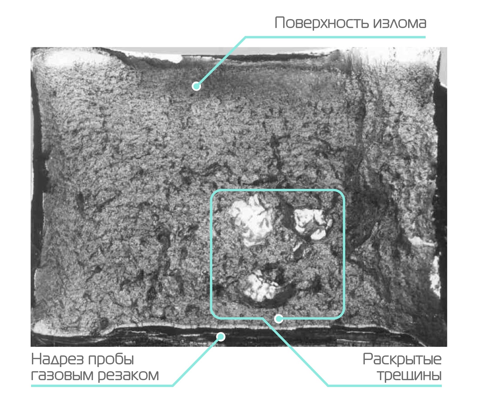
Figure 3. Fracture of a cast technological sample of armor steel with a section of 200x200 mm after complete heat treatment
Do you think that these open cracks were specially polished and silvered? Nothing like this! They so opened up and looked in kind. Imagine the bewilderment of the specialists who saw them in the metal.
The team of engineers together with the employees of the enterprise has done a tremendous job in monitoring and inspecting the technological process. What kind of hypotheses about the origin of these defects were not expressed (up to sabotage)! The impurities of heavy metals were considered guilty, and the light elements - oxygen, sulfur and phosphorus, and magnesium and titanium impurities for some reason. How many disputes, dismissals and reprimands! How many specialists and managers tried to evade responsibility! The working group made a lot of screams. When one big boss lost his voice, research accelerated, - the daily disassemblies made the process very slow. Finally, statistical analysis made it possible to catch some connection between the hydrogen content in steel and the appearance of these defects.
There is always hydrogen in steel. He gets into it in the process of smelting and pouring. Its content, in general, is negligible, about 0.0004–0.0008%. However, due to its lightness, in terms of volume, these minute quantities are about 4-8 ml per 100 g of steel. Another feature of hydrogen due to the small size of its atom is the ability to easily penetrate into the metal in the atomic state even at room temperature, and at temperatures above 400 degrees hydrogen generally walks in steel as it wants.
In the end, it turned out that when the casting is cooled, hydrogen gets into the areas of the interfaces between the steel matrix and microscopic defects that always exist in reality. Once there, hydrogen from an atomic state goes into a molecular one, loses the ability of light diffusion and, accumulating in this defect, develops high pressure, which leads to local destruction of the material. This does not occur simultaneously, and cracks appear gradually. The shiny surface of the cracks is easily explained: hydrogen is an active reducing agent. For this reason, hydrogen-fueled vehicles still do not run on the roads, as special tricks must be applied to protect the armature-conducting armature from its harmful effects. Well, hydrogen cylinders in a car are not a gift either.
When they understood the reason, they began to look for ways to combat the appearance of defects. They introduced and perfected special heat treatment regulations in order to conduct softening tempering of steel until the cracks inside it have time to form. Unfortunately, the search for the truth and the optimal solution was dragged out for years, and it was not immediately possible to completely cope with these defects. Nevertheless, the new technological process, which was extended to all enterprises that manufacture armor castings, eventually allowed defeating defects of this type.
The hydrogen content in accordance with the technical process regulations was monitored in liquid steel: samples were taken from the steel ladle during the casting process and analyzed using specialized analyzers. But how much hydrogen remained in the solid steel after the formation of the casting and after heat treatments was not clear, then how defects were formed in solid steel. Then they carried out a very laborious study: they drilled the technological samples with hollow drills, extracted the core, these samples were cut into small samples with diamond discs. As a result, we got some insight into the behavior of hydrogen during the casting process. But this method of assessing the behavior of hydrogen was completely unsuitable because of its high cost and low-tech.
It was then that in the process of further research in the early 80s a program was developed that allows calculating the concentration of hydrogen in various sections of the casting at different points of its cooling. It was used as an auxiliary tool for confirming the data of direct analysis, which, as noted, were very laborious. In the reports of that period on the study of the state of the metal, this program and the results of calculations are mentioned.
Comparison of the results of program calculations with the actual hydrogen content in steel in castings and sheets satisfied the specialists of the scientific research institute. So, it became possible to adjust the technological process on the basis of estimates of the hydrogen content after various technological regimes. The calculation was also used to estimate the hydrogen content after the so-called profiled treatment of rolled armor. This is a very expensive, time-consuming operation designed to remove hydrogen from steel and to soften it.
Originally the program was created in the Algol language. Due to the relevance of the issue, it was necessary to modify the program in a more modern language. Experts LANIT modernized this program on Delphi.
Now this program has outgrown the area for which it was intended. It is used at the Moscow Institute of Steel and Alloys for scientific calculations, and not only for estimating the concentration of hydrogen, but also nitrogen (for this, it is enough to substitute other diffusion coefficients).
In 2015, the LANIT publishing house released my monograph “Hydrogen in structural steels”, in which the defects of cast steel mentioned here are already described on a scientific and technical level, the negative effect of hydrogen on the mechanical properties of steel and a description of the program with examples of calculations.
Anyone who is interested in this program, I invite you to get acquainted with it (Figure 4).
If you liked my first story, I will tell you about one more episode in which I took an indirect part. Let this story be a bonus. There is not a word about IT, but a lot of explosives =). At once I will make a reservation that this is the view of an eyewitness, as if from the inside. It may differ slightly from the officially adopted chronology and documentation, how the memories of soldiers and lieutenants who participated in the war differ from the official versions of military events.
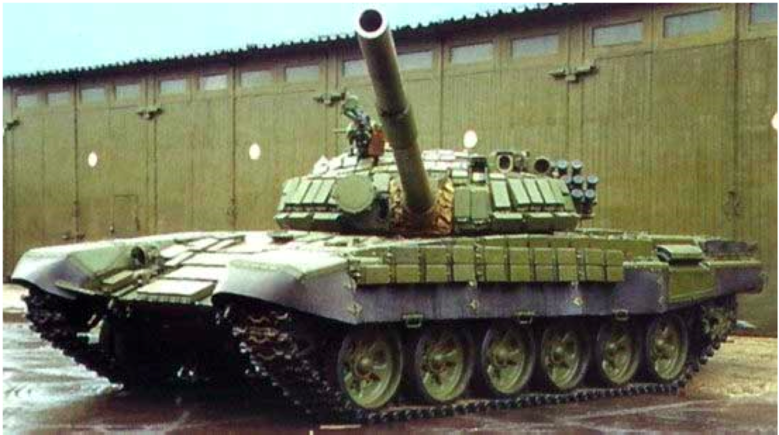
A source
On the turret, front plate and on the sides of this T-72 you see some rectangular elements. Do you know what it is? That's right, these are elements of dynamic protection. I want to tell you about the creation of these elements, moreover, from the side that you are completely unaware of.
At the beginning of the 70s of the last century, in some of our research institutes intensive work was underway to create dynamic protection for tanks. The principle of timely recognition of a quickly flying object using the radar system was laid. It was about installing devices that could recognize a quickly flying object, meet this object and, if not destroy, then at least change its trajectory to reduce its damaging effects.
The task is daunting, since the speed of an armor-piercing projectile is about 650 meters per second, and the sub-caliber is even more than 1400 m / s. If we consider that effective firing from tank and anti-tank guns (as well as anti-tank guided missiles - ATGMs) are conducted from a distance of 1.5–2 km, then everything takes about 2–3 seconds, or even less. In this case, it is necessary to cut off the interference and not make mistakes because of flying sparrows, pigeons, and even bumblebees, which the discriminating system can take for an armor-piercing projectile, and in order not to burn wasted guns on sparrows. In short, there were a lot of difficulties, and a prototype of a working system was not created in those years.
At the beginning of the same seventies, one of my colleagues came to the deputy director of the scientific research institute and said that he had an idea how to design and organize a dynamic defense. In short, the idea was to place on the outside of the turret and the front sheet of the tank some elements with an explosive (BB). When an enemy projectile hits this element, the initiating substance contained in the explosives is triggered, an explosion occurs, and a plate rushes towards the projectile, the projectile partially loses orientation, partially slows down, and its penetration effect decreases significantly. It is impossible to completely stop the projectile, its kinetic energy is too great, but dynamic protection should save the tank from complete failure. Receives bonuses and crew, which, although it can get a concussion, but remains alive and able to successfully continue the fighting.
This idea, as they say, was in the air, and in other organizations there were some sluggish studies of similar devices in a somewhat different form. But the urgency of the implementation of this idea was not ripe, since at that time the cumulative shells of our potential opponents could not penetrate the armor of mass-produced Soviet cars.
The reaction of the science deputy to innovation was unambiguous: “Have you lost your mind? We do not know how to keep the ammunition from detonation inside the tank, but you are still going to hang up the explosives outside the tank. ” In general, the idea of my colleague died in the bud.
After some time, short information appeared in the foreign militaristic literature that work was underway in Israel to install striking elements with explosives on the outside of the tank. (Maybe it was misinformation, it’s impossible to establish it then, and even more so now. It was already later that our allies Arabs during the next conflict captured the Israeli tank Merkava, on which dynamic protection was installed, which confirmed this information). However, this message produced a real shock to the management of the scientific research institute. Damn it, we ourselves almost ruined the idea, it is not known how far behind Israel is in this matter. And once from Israel, it means from America! Moreover, the enemy had cumulative projectiles that pierced cast armor up to 600 mm thick!
Hastily, a team of engineers and scientists was formed that dealt with this problem. In artisanal conditions, metal troughs were made into which explosives were pressed. The samples were first tested on armor elements, then on the mock ups of the turret and hull of the tank, then on real machines at the test sites. The management of the scientific research institute by that time was much younger, it became more agile and quickly removed my colleague from managing the work. The authorities dragged everything on themselves and, at the most severe pace, organized in the conditions of the scientific research institute an almost semi-handicraft production of elements of dynamic protection and the supply of serial machines with them. Subsequently, when some experience had already been gained, the production was transferred to the appropriate military enterprises, which are still engaged in continuous improvement of technology. The systems created have good selectivity and do not work when bullets and fragments hit the protective elements. Tanks without elements of dynamic protection are no longer produced either here or abroad. As a result, our, even outdated, modifications of tanks equipped with elements of dynamic protection (from the experience of combat contacts) retain survivability after being hit by US ATGM TOW.
The creation of dynamic protection using high-speed object recognition devices also continued, and there is some progress in this direction.
I wrote only about two episodes from the history of the creation of Soviet armored vehicles, and how many interesting things there were - and you cannot count. It is thanks to such breakthrough moments that our weapons and now surpasses foreign models.
While the world powers continue to compete in military equipment and demonstrate more sophisticated models of armored vehicles, I want to tell you a couple of stories from the Soviet tank building. Moreover, many modern models are nothing more than the latest modifications of the machines of the famous series.
In these stories I took either indirectly or directly and saw what difficulties designers and technologists had to overcome.
')
It will be in my story and about information technology, because it was IT at one time that helped correct serious manufacturing defects, over which a whole team of engineers struggled.
Figure 1. Source
Before you is a T-72 tank, produced at Uralvagonzavod. This is one of the first modifications of the tank of this series with a cast turret.
Cast turrets were used in the T-34 tank. This made it possible to obtain a component with a complex configuration, leaving only a few elements of its structure to be finished by machining. At the same time, it was a difficult cast. Its casting weight with profits and sprues reached 15 tons.
Figure 2. T-64 tank early releases of the Kharkov plant them. Malysheva (also with a cast tower) Source
Towers cast almost identical technology in Mariupol, Chelyabinsk and Omsk. And then one day, by no means a wonderful day, in the casting towers produced at different factories, defects were found which caused, to put it mildly, bewilderment among the foundry workers. These defects were detected in the frontal part of the casting after the boring of wells under the trunnion of the gun, and they looked on the treated surface as thin cracks scattered randomly over the bored surface. Naturally, the representative of the customer rejected such castings, and in order not to send the expensive casting to remelting, a complicated operation of cutting the cracks with manual pneumatic chisels to a solid body followed by welding was performed.
The appearance of such defects has become widespread in the three enterprises listed above (up to 15% (!) Of the total number of castings). It is possible to imagine what resonance this caused in the management of the plants and in the relevant ministry. A team of enterprise managers, scientists and engineers was urgently created, which was sent to Mariupol with the task of working until the defects were eliminated.
A brief excursion into technology
Together with the casting of the tower, so-called technological samples are being cast, which accompany the tower in all heat treatment operations. After the end of the casting process, the samples are broken on a scraper and judging by the type of fracture, the quality of steel and the quality of heat treatment are judged. By the way, the same procedure with technological samples takes place in the manufacture of rolled armor.
The fracture, as a characteristic of steel, has been known since the days of the Russian metallurgist Pavel Petrovich Anosov (the same one who worked on bulat). The use of this tool for an exhaustive description of the quality of steel instead of long-term tests of mechanical properties is by no means a Russian anachronism. The fracture, indeed, very accurately describes the quality of steelmaking and the quality of its heat treatment. Special reference scales have been developed, in comparison with which, receivers and customer representatives check the quality of the metal.
When control tests began to be broken in production, the very hairline cracks that were found in the towers appeared in a fracture, as in Figure 3 below.
Figure 3. Fracture of a cast technological sample of armor steel with a section of 200x200 mm after complete heat treatment
Do you think that these open cracks were specially polished and silvered? Nothing like this! They so opened up and looked in kind. Imagine the bewilderment of the specialists who saw them in the metal.
The team of engineers together with the employees of the enterprise has done a tremendous job in monitoring and inspecting the technological process. What kind of hypotheses about the origin of these defects were not expressed (up to sabotage)! The impurities of heavy metals were considered guilty, and the light elements - oxygen, sulfur and phosphorus, and magnesium and titanium impurities for some reason. How many disputes, dismissals and reprimands! How many specialists and managers tried to evade responsibility! The working group made a lot of screams. When one big boss lost his voice, research accelerated, - the daily disassemblies made the process very slow. Finally, statistical analysis made it possible to catch some connection between the hydrogen content in steel and the appearance of these defects.
Insidious hydrogen
There is always hydrogen in steel. He gets into it in the process of smelting and pouring. Its content, in general, is negligible, about 0.0004–0.0008%. However, due to its lightness, in terms of volume, these minute quantities are about 4-8 ml per 100 g of steel. Another feature of hydrogen due to the small size of its atom is the ability to easily penetrate into the metal in the atomic state even at room temperature, and at temperatures above 400 degrees hydrogen generally walks in steel as it wants.
In the end, it turned out that when the casting is cooled, hydrogen gets into the areas of the interfaces between the steel matrix and microscopic defects that always exist in reality. Once there, hydrogen from an atomic state goes into a molecular one, loses the ability of light diffusion and, accumulating in this defect, develops high pressure, which leads to local destruction of the material. This does not occur simultaneously, and cracks appear gradually. The shiny surface of the cracks is easily explained: hydrogen is an active reducing agent. For this reason, hydrogen-fueled vehicles still do not run on the roads, as special tricks must be applied to protect the armature-conducting armature from its harmful effects. Well, hydrogen cylinders in a car are not a gift either.
IT to help
When they understood the reason, they began to look for ways to combat the appearance of defects. They introduced and perfected special heat treatment regulations in order to conduct softening tempering of steel until the cracks inside it have time to form. Unfortunately, the search for the truth and the optimal solution was dragged out for years, and it was not immediately possible to completely cope with these defects. Nevertheless, the new technological process, which was extended to all enterprises that manufacture armor castings, eventually allowed defeating defects of this type.
The hydrogen content in accordance with the technical process regulations was monitored in liquid steel: samples were taken from the steel ladle during the casting process and analyzed using specialized analyzers. But how much hydrogen remained in the solid steel after the formation of the casting and after heat treatments was not clear, then how defects were formed in solid steel. Then they carried out a very laborious study: they drilled the technological samples with hollow drills, extracted the core, these samples were cut into small samples with diamond discs. As a result, we got some insight into the behavior of hydrogen during the casting process. But this method of assessing the behavior of hydrogen was completely unsuitable because of its high cost and low-tech.
It was then that in the process of further research in the early 80s a program was developed that allows calculating the concentration of hydrogen in various sections of the casting at different points of its cooling. It was used as an auxiliary tool for confirming the data of direct analysis, which, as noted, were very laborious. In the reports of that period on the study of the state of the metal, this program and the results of calculations are mentioned.
Comparison of the results of program calculations with the actual hydrogen content in steel in castings and sheets satisfied the specialists of the scientific research institute. So, it became possible to adjust the technological process on the basis of estimates of the hydrogen content after various technological regimes. The calculation was also used to estimate the hydrogen content after the so-called profiled treatment of rolled armor. This is a very expensive, time-consuming operation designed to remove hydrogen from steel and to soften it.
Originally the program was created in the Algol language. Due to the relevance of the issue, it was necessary to modify the program in a more modern language. Experts LANIT modernized this program on Delphi.
Now this program has outgrown the area for which it was intended. It is used at the Moscow Institute of Steel and Alloys for scientific calculations, and not only for estimating the concentration of hydrogen, but also nitrogen (for this, it is enough to substitute other diffusion coefficients).
In 2015, the LANIT publishing house released my monograph “Hydrogen in structural steels”, in which the defects of cast steel mentioned here are already described on a scientific and technical level, the negative effect of hydrogen on the mechanical properties of steel and a description of the program with examples of calculations.
Anyone who is interested in this program, I invite you to get acquainted with it (Figure 4).
Later in the spoiler are the detailed calculations that the program uses.
Figure 4. Block diagram of the program for calculating the residual hydrogen content in castings and thick sheets
The calculation is based on the solution of the differential diffusion equation for the two-dimensional case, that is, when considering the distribution of hydrogen in a cross section of a sheet of infinitely large length. The solution of the diffusion equation is a series of the form:
(one)
(xyt) is the hydrogen concentration at the current time t at the point with coordinates x m , y n .
i is the partitioning step along the x coordinate;
j is the partitioning step along the y coordinate;
a is the size of the sheet in the x coordinate;
b - sheet size on the y coordinate.
Initial conditions must be specified for the calculation, for example:
The initial concentration of hydrogen in the metal ingot - 5 cm 3/100 g
The initial concentration of hydrogen in the metal casting - 7 cm 3/100 g
(2)

This means that at the initial moment of time the concentration of hydrogen over the sheet section is uniform and equal to the initial concentration c 1 ; after a considerable period of time the concentration of hydrogen drops to zero.
Boundary conditions should also be specified:
(3)
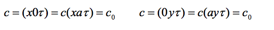
This record means that the hydrogen concentration on the surface of the casting or billet is assumed to be zero during the entire degassing process.
The solution of the diffusion equation with the help of series (1) is reduced to calculating the concentration C at points with coordinates x m y n for integral time moments
(four)

D - diffusion coefficient cm 2 / c;
T is temperature about ;
t is time.
When calculating it is necessary to choose the values of the diffusion coefficients of hydrogen in steel. These values may vary for different temperatures and different structural states of steel.
For example, the object of the calculations is the structural medium-alloyed steel containing carbon 0.3%, as well as chromium, nickel and molybdenum (the amount of alloying 4%). When cooled in the temperature range of 1000-300 o C, the diffusion coefficient of hydrogen in this steel is described by the Arrhenius equation with the following coefficients:
(five)

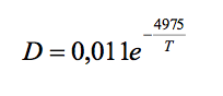
When cooled in the temperature range 300–20 ° C, the diffusion coefficient of hydrogen can be described by another expression:
(6)
The numerical coefficients in these equations are substituted into the appropriate program window.
Data is entered into the program in the Kinput.ini file (the file is opened using the Windows Notepad program - Figure 5).

Figure 5. Window for loading data into the program
In this file, the numerical values of the initial conditions are entered:
I1 is the number of points specified in the temperature table, reduced by 1.
J1 - the number of layers into which the sheet thickness is divided.
L1 = 2 - the number of points in the cross section of the steel sheet, in which the hydrogen concentration is estimated.
DT = 30 - observation time interval, min.
C0 = 5 - the initial concentration of hydrogen in the metal, cm 3 / 100g.
H1 = 50 - width of the sheet (or casting), in cm.
H2 = 8.5 - the thickness of the sheet (or casting), see
DG1 = 0.00076 - coefficient in equation (5).
DG2 = 1140 is the numerator of the fraction in equation (5).
DL1 = 0.011 is the coefficient in equation (6).
DL2 = 4975 is the numerator of the fraction in equation (6).
You can optionally enter other values of the coefficients in the equations for the dependence of diffusion on temperature and carry out the necessary calculations. It is also possible to carry out calculations on the distribution of nitrogen during cooling of steel billets by entering the necessary values of the diffusion coefficients.
Attention! Numerical values in each line after the [INPUT] and [X] headers are allowed to be entered only to the right of the equal sign. Values and signs, standing before the equal sign, belong to the program and cannot be changed!
The numerical values of the boundary conditions are also introduced:
[X]
1 = 25; 4.3 - coordinates of the first point for which the calculation is carried out, see
2 = 25; 2.1 - coordinates of the second point for which the calculation is carried out, see
In the process of calculation, the temperature change is given by tabular values depending on the time for the serial and experimental modes of the PFD, as well as tabular values of lowering the temperature of the casting in the process of cooling it in the form based on graphs taken during the cooling of real sheets and castings. Data entry is performed, for example, in the following form:
[TIME_TEMPER]
0 = 0; 800
1 = 30; 789
2 = 60; 779
3 = 90; 768
... = ...; ..., where 0, 1, 2, 3 are steps; 0, 30, 60 - time in minutes; 800, 789, 779 — temperature values corresponding to time 0, 30, 60, etc.
Having entered the necessary values, you should give the command “Save” by pressing the key combination Ctrl + S. Next, you need to open the program window by double clicking the left mouse button on the program icon and after the appearance of the screen form, activate the “Load” button on it (Figure 6).

Figure 6. Calculation program window
The data for the calculations will then be entered into the program table, and the Start button will become active. After activating the Start button, the program will perform the calculation, and after activating the Button2 button, the calculation results will be recorded in the Koutput.ini file (Figure 7). To view the table with the calculation data you need to open this file, copy the table and transfer it to Excel editor for further processing (graphing, table formation, etc.).
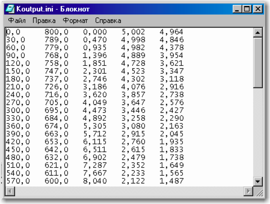
Figure 7. Table with the results of the calculation
Before you (Figure 8), the calculation results in Excel Editor of the hydrogen concentration in the section of a steel sheet (see the table with the results of the calculation), cooled according to a certain mode, given in the table on the screen (see the window for loading data into the program). 1 - sheet cooling curve; 2 - hydrogen concentration in the center of the sheet thickness; 3 - concentration at a distance of ¼ sheet thickness.

Figure 8. The result of the calculation in the form of graphs
Figure 4. Block diagram of the program for calculating the residual hydrogen content in castings and thick sheets
The calculation is based on the solution of the differential diffusion equation for the two-dimensional case, that is, when considering the distribution of hydrogen in a cross section of a sheet of infinitely large length. The solution of the diffusion equation is a series of the form:
(one)
(xyt) is the hydrogen concentration at the current time t at the point with coordinates x m , y n .
i is the partitioning step along the x coordinate;
j is the partitioning step along the y coordinate;
a is the size of the sheet in the x coordinate;
b - sheet size on the y coordinate.
Initial conditions must be specified for the calculation, for example:
The initial concentration of hydrogen in the metal ingot - 5 cm 3/100 g
The initial concentration of hydrogen in the metal casting - 7 cm 3/100 g
(2)
This means that at the initial moment of time the concentration of hydrogen over the sheet section is uniform and equal to the initial concentration c 1 ; after a considerable period of time the concentration of hydrogen drops to zero.
Boundary conditions should also be specified:
(3)
This record means that the hydrogen concentration on the surface of the casting or billet is assumed to be zero during the entire degassing process.
The solution of the diffusion equation with the help of series (1) is reduced to calculating the concentration C at points with coordinates x m y n for integral time moments
(four)
D - diffusion coefficient cm 2 / c;
T is temperature about ;
t is time.
When calculating it is necessary to choose the values of the diffusion coefficients of hydrogen in steel. These values may vary for different temperatures and different structural states of steel.
For example, the object of the calculations is the structural medium-alloyed steel containing carbon 0.3%, as well as chromium, nickel and molybdenum (the amount of alloying 4%). When cooled in the temperature range of 1000-300 o C, the diffusion coefficient of hydrogen in this steel is described by the Arrhenius equation with the following coefficients:
(five)
When cooled in the temperature range 300–20 ° C, the diffusion coefficient of hydrogen can be described by another expression:
(6)
The numerical coefficients in these equations are substituted into the appropriate program window.
Data is entered into the program in the Kinput.ini file (the file is opened using the Windows Notepad program - Figure 5).
Figure 5. Window for loading data into the program
In this file, the numerical values of the initial conditions are entered:
I1 is the number of points specified in the temperature table, reduced by 1.
J1 - the number of layers into which the sheet thickness is divided.
L1 = 2 - the number of points in the cross section of the steel sheet, in which the hydrogen concentration is estimated.
DT = 30 - observation time interval, min.
C0 = 5 - the initial concentration of hydrogen in the metal, cm 3 / 100g.
H1 = 50 - width of the sheet (or casting), in cm.
H2 = 8.5 - the thickness of the sheet (or casting), see
DG1 = 0.00076 - coefficient in equation (5).
DG2 = 1140 is the numerator of the fraction in equation (5).
DL1 = 0.011 is the coefficient in equation (6).
DL2 = 4975 is the numerator of the fraction in equation (6).
You can optionally enter other values of the coefficients in the equations for the dependence of diffusion on temperature and carry out the necessary calculations. It is also possible to carry out calculations on the distribution of nitrogen during cooling of steel billets by entering the necessary values of the diffusion coefficients.
Attention! Numerical values in each line after the [INPUT] and [X] headers are allowed to be entered only to the right of the equal sign. Values and signs, standing before the equal sign, belong to the program and cannot be changed!
The numerical values of the boundary conditions are also introduced:
[X]
1 = 25; 4.3 - coordinates of the first point for which the calculation is carried out, see
2 = 25; 2.1 - coordinates of the second point for which the calculation is carried out, see
In the process of calculation, the temperature change is given by tabular values depending on the time for the serial and experimental modes of the PFD, as well as tabular values of lowering the temperature of the casting in the process of cooling it in the form based on graphs taken during the cooling of real sheets and castings. Data entry is performed, for example, in the following form:
[TIME_TEMPER]
0 = 0; 800
1 = 30; 789
2 = 60; 779
3 = 90; 768
... = ...; ..., where 0, 1, 2, 3 are steps; 0, 30, 60 - time in minutes; 800, 789, 779 — temperature values corresponding to time 0, 30, 60, etc.
Having entered the necessary values, you should give the command “Save” by pressing the key combination Ctrl + S. Next, you need to open the program window by double clicking the left mouse button on the program icon
and after the appearance of the screen form, activate the “Load” button on it (Figure 6).Figure 6. Calculation program window
The data for the calculations will then be entered into the program table, and the Start button will become active. After activating the Start button, the program will perform the calculation, and after activating the Button2 button, the calculation results will be recorded in the Koutput.ini file (Figure 7). To view the table with the calculation data you need to open this file, copy the table and transfer it to Excel editor for further processing (graphing, table formation, etc.).
Figure 7. Table with the results of the calculation
Before you (Figure 8), the calculation results in Excel Editor of the hydrogen concentration in the section of a steel sheet (see the table with the results of the calculation), cooled according to a certain mode, given in the table on the screen (see the window for loading data into the program). 1 - sheet cooling curve; 2 - hydrogen concentration in the center of the sheet thickness; 3 - concentration at a distance of ¼ sheet thickness.
Figure 8. The result of the calculation in the form of graphs
If you liked my first story, I will tell you about one more episode in which I took an indirect part. Let this story be a bonus. There is not a word about IT, but a lot of explosives =). At once I will make a reservation that this is the view of an eyewitness, as if from the inside. It may differ slightly from the officially adopted chronology and documentation, how the memories of soldiers and lieutenants who participated in the war differ from the official versions of military events.
Do not shoot at sparrows
A source
On the turret, front plate and on the sides of this T-72 you see some rectangular elements. Do you know what it is? That's right, these are elements of dynamic protection. I want to tell you about the creation of these elements, moreover, from the side that you are completely unaware of.
At the beginning of the 70s of the last century, in some of our research institutes intensive work was underway to create dynamic protection for tanks. The principle of timely recognition of a quickly flying object using the radar system was laid. It was about installing devices that could recognize a quickly flying object, meet this object and, if not destroy, then at least change its trajectory to reduce its damaging effects.
The task is daunting, since the speed of an armor-piercing projectile is about 650 meters per second, and the sub-caliber is even more than 1400 m / s. If we consider that effective firing from tank and anti-tank guns (as well as anti-tank guided missiles - ATGMs) are conducted from a distance of 1.5–2 km, then everything takes about 2–3 seconds, or even less. In this case, it is necessary to cut off the interference and not make mistakes because of flying sparrows, pigeons, and even bumblebees, which the discriminating system can take for an armor-piercing projectile, and in order not to burn wasted guns on sparrows. In short, there were a lot of difficulties, and a prototype of a working system was not created in those years.
Explosives against shells
At the beginning of the same seventies, one of my colleagues came to the deputy director of the scientific research institute and said that he had an idea how to design and organize a dynamic defense. In short, the idea was to place on the outside of the turret and the front sheet of the tank some elements with an explosive (BB). When an enemy projectile hits this element, the initiating substance contained in the explosives is triggered, an explosion occurs, and a plate rushes towards the projectile, the projectile partially loses orientation, partially slows down, and its penetration effect decreases significantly. It is impossible to completely stop the projectile, its kinetic energy is too great, but dynamic protection should save the tank from complete failure. Receives bonuses and crew, which, although it can get a concussion, but remains alive and able to successfully continue the fighting.
This idea, as they say, was in the air, and in other organizations there were some sluggish studies of similar devices in a somewhat different form. But the urgency of the implementation of this idea was not ripe, since at that time the cumulative shells of our potential opponents could not penetrate the armor of mass-produced Soviet cars.
For reference
The average lifespan of a tank in battle is 12 minutes (according to the experience of the Second World War and the experience of participation of tank units in modern conflicts). This is the so-called life cycle of this product.
The reaction of the science deputy to innovation was unambiguous: “Have you lost your mind? We do not know how to keep the ammunition from detonation inside the tank, but you are still going to hang up the explosives outside the tank. ” In general, the idea of my colleague died in the bud.
After some time, short information appeared in the foreign militaristic literature that work was underway in Israel to install striking elements with explosives on the outside of the tank. (Maybe it was misinformation, it’s impossible to establish it then, and even more so now. It was already later that our allies Arabs during the next conflict captured the Israeli tank Merkava, on which dynamic protection was installed, which confirmed this information). However, this message produced a real shock to the management of the scientific research institute. Damn it, we ourselves almost ruined the idea, it is not known how far behind Israel is in this matter. And once from Israel, it means from America! Moreover, the enemy had cumulative projectiles that pierced cast armor up to 600 mm thick!
Catch up and overtake
Hastily, a team of engineers and scientists was formed that dealt with this problem. In artisanal conditions, metal troughs were made into which explosives were pressed. The samples were first tested on armor elements, then on the mock ups of the turret and hull of the tank, then on real machines at the test sites. The management of the scientific research institute by that time was much younger, it became more agile and quickly removed my colleague from managing the work. The authorities dragged everything on themselves and, at the most severe pace, organized in the conditions of the scientific research institute an almost semi-handicraft production of elements of dynamic protection and the supply of serial machines with them. Subsequently, when some experience had already been gained, the production was transferred to the appropriate military enterprises, which are still engaged in continuous improvement of technology. The systems created have good selectivity and do not work when bullets and fragments hit the protective elements. Tanks without elements of dynamic protection are no longer produced either here or abroad. As a result, our, even outdated, modifications of tanks equipped with elements of dynamic protection (from the experience of combat contacts) retain survivability after being hit by US ATGM TOW.
The creation of dynamic protection using high-speed object recognition devices also continued, and there is some progress in this direction.
I wrote only about two episodes from the history of the creation of Soviet armored vehicles, and how many interesting things there were - and you cannot count. It is thanks to such breakthrough moments that our weapons and now surpasses foreign models.
Source: https://habr.com/ru/post/327368/
All Articles