Detect and track multiple objects in a video stream on an FPGA
In this article I want to talk about the implementation of the system for detecting and tracking multiple objects in a video stream. This article is based on the two previous ones: Motion detection in a video stream on FPGA and Image filtering using the method of mathematical morphology on FPGA . Capture and initial image processing is carried out using the methods described in the first article, and image filtering is described in the second.
Following the goals set in the first article, I decided to implement an algorithm for drawing a frame around the detected object. In the process of performing this task, I was faced with the question: what frame should I draw around exactly what object? There may be many objects in the frame after filtering: some of them are small and others are large. If you draw one frame around all the objects in the frame, this is not difficult, but the result of the work of such a system is unlikely to be interesting to anyone.
Rummaging in the network, I got acquainted with a variety of documents describing different approaches to the detection of multiple objects. Some turned out to be unsuitable for implementation on the FPGA, others require large amounts of block memory to store the whole frame, others do the work in several passes through the image, which is also not suitable in my case. I want for one.
Nevertheless, one of the documents attracted my attention. It describes an algorithm that implements the detection of multiple objects in a single pass through the image using the implementation of linked lists for analyzing image areas. After analyzing this material, I realized that this algorithm suits me, provided that the object detector itself will work in a faster clok domain than the logic of entering data into the detector and displaying the image on the screen. This is due to the fact that this algorithm searches through linked lists with each new piece of data received at its input, and the number of linked lists at the maximum reaches a value of half the number of pixels in a row. In other words, in the worst case, with each new piece of data we need to process 160 linked lists if the width of the line of our image is 320 pixels.
')
Below is a functional diagram of the detector of multiple objects:
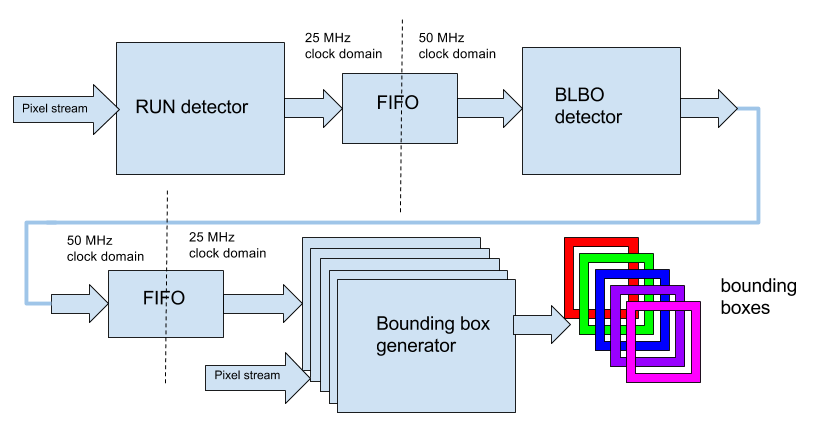
The detector consists of three main blocks: RUN detector , BLOB detector and Bounding box generator . Each block operates in its own klokov domain and is connected to another block via an asynchronous FIFO.
RUN detector
The input data of this block are the output data from the filter based on mathematical morphology .
This block searches for the input stream of a sequence of pixels consisting of one units, the so-called RUNs. This name is taken from the RLE (Run Length Encoding) compression algorithm used for JPEG compression and the like. The picture below shows several types of RUNs: class-length , class-start and start-end .
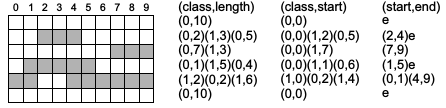
In our detector, the last one is used ( start-end ). It is most suitable for our system. In the start field, the initial position of the sequence of units is recorded, and in the end field, the end position, then the generated start-end field is transmitted to the RUN output of the detector and written to the FIFO. Along with RUNs, the end of line and end of frame data are recorded in the FIFO for the next block to work correctly.
Verilog Detector Code
Run detector
module run_detector #( parameter RES_X=10'd320, parameter RES_Y=10'd240, parameter XOFFSET=10'd320, parameter YOFFSET=10'd0) ( input wire clk, input wire nRst, input wire data_valid, input wire [0:0] data_in, input wire [10:0] xi, input wire [10:0] yi, output reg [9:0] run_start, output reg [9:0] run_end, output reg row_end, output reg frame_end, output reg new_run, output reg rd_req ); localparam ST_IDLE=0, ST_RUN_START=1, ST_RUN_END=2, ST_ROW_END=3, ST_FRAME_END=4; localparam XRES = RES_X + XOFFSET - 1; localparam YRES = RES_Y + YOFFSET - 1; reg [2:0] run_state = 0; reg [9:0] run_start_d; reg [9:0] run_end_d; wire row_done_w = ((xi == XRES) && (yi <= YRES)) ? 1'b1:1'b0; wire frame_done_w = ((xi == XRES) && (yi == YRES)) ? 1'b1:1'b0; always @(posedge clk or negedge nRst) if (!nRst) begin run_state <= ST_IDLE; run_start <= 10'd0; run_end <= 10'd0; row_end <= 1'b0; frame_end <= 1'b0; new_run <= 1'b0; rd_req <= 1'b0; end else begin new_run <= 1'b0; row_end <= 1'b0; frame_end <= 1'b0; case (run_state) ST_IDLE: begin if (data_valid) begin if (data_in) begin run_state <= ST_RUN_START; run_start <= xi[9:0]; end end end ST_RUN_START: begin if (!data_in) begin run_state <= ST_RUN_END; run_end <= xi[9:0] - 1'b1; new_run <= 1'b1; end end ST_RUN_END: begin if (data_in) begin run_start <= xi[9:0]; run_state <= ST_RUN_START; end else begin run_state <= ST_IDLE; end end ST_ROW_END, ST_FRAME_END: begin if (!data_valid) begin run_state <= ST_IDLE; end end endcase if (row_done_w || frame_done_w) begin run_state <= frame_done_w ? ST_FRAME_END : ST_ROW_END; row_end <= row_done_w ? 1'b1 : 1'b0; frame_end <= frame_done_w ? 1'b1 : 1'b0; run_start <= 10'd0; run_end <= 10'd0; new_run <= 1'b1; end end endmodule BLOB detector
A flowchart of the detector is shown below.
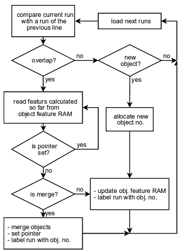
Consider the work of the detector in more detail. The detector, in my implementation, is a large synchronous state machine. Also, two modules of block memory are used for the detector operation: one for storing RUNs ( run memory ) of the current and previous lines, the second for storing properties of the detected object ( object memory ). Total 32 objects.
INIT
The detector starts in the INIT state. In this state, one of the run memory buffers is initialized with invalid label values. Then the detector enters the IDLE state.
IDLE
In this state, the detector waits for data in the input FIFO from the RUN detector, then enters the FIND_RUN state.
FIND_RUN
Here the detector reads the start and end coordinates of the RUN from the FIFO and goes to the FIND_OVERLAP state to search for the intersections of the current RUN with the RUNs of the previous line. A new RUN is assigned an invalid tag.
FIND_OVERLAP
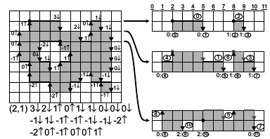
The data in the memory of run memory is located in 2 rows - the current and the previous one. Each new RUN from the FIFO is recorded in the current memory block and by passing through the entire block of the previous line is compared for intersections (overlaps). The figure below illustrates how RUNs are stored in run memory .
If the read from the memory of the previous RUN line has a invalid tag, this means that there are no more RUNs of the previous line in this block, and the detector switches to the CREATE_OBJ state to create a new object from the current RUN. Otherwise, if the intersection is set, then the object is read from the object memory at the address of the RUN tag and the detector switches to the UPDATE_OBJ state to update the properties of an already existing object. If the current RUN has a label that is not invalid, given to it from reading from the FIFO, then this means that this RUN belongs to some object and there was an intersection with another existing object and these objects need to be merged into one object, and the detector enters the MERGE_OBJ state.
CREATE_OBJ
Here a new object is created, all its properties are filled.
- X start - Starting X coordinate
- X end - The final X coordinate
- Y start - Starting Y coordinate
- Y end - the final coordinate Y
- Object mass - The number of pixels in the object.
The created object is stored in object memory at the next free address (label of the current RUN). The detector enters the IDLE state of reading a new RUN from the FIFO.
UPDATE_OBJ
In this state, the properties of an existing object from object memory are updated, new coordinates of the object are calculated based on the length of the current RUN being attached to it. After the object has been updated, the detector enters the FIND_OVERLAP state of the intersection search with the next RUN from the run memory.
MERGE_OBJ
Here, two existing objects merge into one, their properties are updated and assigned to the first object, and the second object is invalidated to be excluded from subsequent processing. After the merge, the detector enters the FIND_OVERLAP state of intersection search with the next RUN from the run memory .
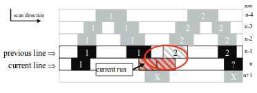
The figure below shows the merging of objects 1 and 2 by means of a common RUN-a shaded in red.
FINISH_OBJ
The detector enters this state every time when a sign of the end of the line or the end of the frame is read from the FIFO. In the case of a line terminator, the write and read areas in the run memory are swapped and the detector enters the state of waiting for data from the FIFO. In the case of the end of the frame, the detector enters the UPLOAD_DATA state of unloading the objects found from the object memory into the output FIFO.
UPLOAD_DATA
Passing through the entire object memory, the object properties are unloaded into the output FIFO. The word unloaded in the FIFO is the layout of the address of the object and the four coordinates Xstart , Xend , Ystart and Yend . A total of 32 objects are implemented and this is quite enough for a frame of 320x240 pixels. But not all found objects will be valid. Objects with a mass of less than 100 pixels will be unloaded into the output FIFO as invalid and subsequently will not be processed by the frame generator. After unloading all objects, the detector erases all object memory and changes its state to START , and a new cycle of accumulation of objects begins.
Verilog Detector Code
Blob detector
module blob_detector #( parameter RES_X=10'd320, parameter RES_Y=10'd240) ( input wire clk, input wire nRst, // input RUN FIFO input wire fifo_empty, input wire [21:0] fifo_data, output wire fifo_rd_en, // output boxes interface output reg we, output reg [47:0] data_o ); localparam ST_START = 0, ST_INIT = 1, ST_IDLE = 2, ST_FIND_RUN = 3, ST_FIND_OVERLAP = 4, ST_FIND_OVERLAP_0 = 5, ST_CREATE_OBJ = 6, ST_UPDATE_OBJ_2 = 7, ST_UPDATE_OBJ = 8, ST_MERGE_OBJ = 9, ST_MERGE_OBJ_2 = 10, ST_FINISH_OBJ = 11, ST_FINISH_OBJ_2 = 12, ST_UPLOAD_DATA_START = 13, ST_UPLOAD_DATA = 14, ST_UPLOAD_DATA_END = 15; localparam MAX_RUNS = RES_X >> 1; //`define DETECTOR_DEBUG_MODE //is using for modeling // RUN memory reg [7:0] run_mem_wr_addr = 0; reg [7:0] run_mem_rd_addr = 0; reg [7:0] run_mem_saved_addr = 0; reg run_mem_wr_en = 0; reg run_mem_flip = 0; // RUN memory data wire [9:0] run_rd_start_x; wire [9:0] run_rd_end_x; wire [9:0] run_rd_label; // RUN FIFO data reg [9:0] run_cur_start_x = 0; reg [9:0] run_cur_end_x = 0; reg [9:0] run_cur_label = 0; wire [1:0] eb; reg [9:0] free_label = 0; `define OBJ_MASS_THR 19'd100 `define OBJ_LIMIT 32 `define FRAME_END fifo_data[21] `define ROW_CHANGED fifo_data[20] `define RUN_EMPTY_LABEL 10'h200 `define EMPY_RUN_SLOT 10'h1FF // FSM reg [5:0] blob_detector_fsm_state = 0; // Internal reg [9:0] current_row = 0; reg [9:0] temp_label = 0; reg frame_end_r = 0; `ifdef DETECTOR_DEBUG_MODE // DEBUG reg create_obj = 0; reg merge_obj = 0; reg update_obj = 0; reg skip_obj = 0; reg finish_obj = 0; wire [8:0] rd_ram_addr = {~run_mem_flip, run_mem_rd_addr}; wire [8:0] wr_ram_addr = {run_mem_flip, run_mem_wr_addr}; `endif // read the input FIFO assign fifo_rd_en = (!fifo_empty && blob_detector_fsm_state == ST_FIND_RUN); // RUN memory alt_ram_30x512 run_ram ( .clock(clk), .data({2'h0, run_cur_start_x, run_cur_end_x, run_cur_label}), .rdaddress({~run_mem_flip, run_mem_rd_addr}), .wraddress({run_mem_flip, run_mem_wr_addr}), .wren(run_mem_wr_en), .q({eb, run_rd_start_x, run_rd_end_x, run_rd_label}) ); reg [4:0] obj_wr_addr = 0, obj_rd_addr = 0, obj_saved_rd_addr = 0; reg obj_mem_wr_en = 0; // object's fields for writing reg [9:0] obj_start_x = 0, obj_start_y = 0, obj_end_x = 0, obj_end_y = 0; reg [21:0] obj_mass = 0; reg obj_valid = 0, obj_updated = 0; // object's wires for reading wire [9:0] obj_rd_start_x, obj_rd_start_y, obj_rd_end_x, obj_rd_end_y; wire [21:0] obj_rd_mass; wire obj_rd_valid, obj_rd_updated; // object detection condition wire obj_detected_valid = (obj_rd_valid && (obj_rd_mass > `OBJ_MASS_THR)); // Object memory object_ram obj_ram ( .clock(clk), .data({obj_valid,obj_updated,obj_start_x,obj_end_x,obj_start_y,obj_end_y,obj_mass}), .rdaddress(obj_rd_addr), .wraddress(obj_wr_addr), .wren(obj_mem_wr_en), .q({obj_rd_valid,obj_rd_updated,obj_rd_start_x,obj_rd_end_x,obj_rd_start_y,obj_rd_end_y,obj_rd_mass}) ); /* * The main detector process */ always @(posedge clk or negedge nRst) if (!nRst) begin blob_detector_fsm_state <= ST_START; run_mem_flip <= 1'b0; free_label <= 10'd0; temp_label <= 10'd0; current_row <= 10'd0; frame_end_r <= 1'b0; run_mem_wr_en <= 1'b0; obj_mem_wr_en <= 1'b0; we <= 1'b0; end else begin run_mem_wr_en <= 1'b0; obj_mem_wr_en <= 1'b0; we <= 1'b0; `ifdef DETECTOR_DEBUG_MODE // DEBUG create_obj <= 1'b0; merge_obj <= 1'b0; update_obj <= 1'b0; skip_obj <= 1'b0; finish_obj <= 1'b0; `endif case (blob_detector_fsm_state) ST_START: begin current_row <= 10'd0; free_label <= 10'd0; run_mem_rd_addr <= 8'd0; run_mem_wr_addr <= 8'd0; obj_rd_addr <= 5'd0; obj_wr_addr <= 5'd0; frame_end_r <= 1'b0; run_mem_flip <= 1'b0; blob_detector_fsm_state <= ST_INIT; run_cur_start_x <= `EMPY_RUN_SLOT; run_cur_end_x <= `EMPY_RUN_SLOT; run_mem_wr_en <= 1'b1; end ST_INIT: begin if (run_mem_wr_addr >= MAX_RUNS) begin run_mem_wr_addr <= 8'd0; run_mem_flip <= ~run_mem_flip; run_mem_wr_en <= 1'b0; blob_detector_fsm_state <= ST_IDLE; end else begin run_mem_wr_addr <= run_mem_wr_addr + 1'b1; run_mem_wr_en <= 1'b1; end end ST_IDLE: begin if (!fifo_empty) begin blob_detector_fsm_state <= ST_FIND_RUN; end end ST_FIND_RUN: begin // fifo is already read by now // ALWAYS set the empty label to the new run temp_label <= `RUN_EMPTY_LABEL; run_cur_start_x <= fifo_data[19:10]; run_cur_end_x <= fifo_data[9:0]; if (`ROW_CHANGED) begin frame_end_r <= `FRAME_END; blob_detector_fsm_state <= ST_FINISH_OBJ; end else begin // set first read addres of a RUN run_mem_rd_addr <= 8'd0; blob_detector_fsm_state <= ST_FIND_OVERLAP_0; end end ST_FIND_OVERLAP_0: begin // an empty case (altera's altsyncram is read in 2 cycles, one of them is empty) blob_detector_fsm_state <= ST_FIND_OVERLAP; end ST_FIND_OVERLAP: begin if ((run_rd_start_x == `EMPY_RUN_SLOT) || (run_rd_start_x > run_cur_end_x + 1'b1)) begin // create new object if (temp_label == `RUN_EMPTY_LABEL) begin // asssign the run a free label run_cur_label <= free_label; // ??? obj_saved_rd_addr <= obj_rd_addr; obj_rd_addr <= free_label[4:0]; // store current run into the memory run_mem_wr_en <= 1'b1; blob_detector_fsm_state <= ST_CREATE_OBJ; end else begin // some garbage was read from the FIFO run_mem_rd_addr <= 8'd0; blob_detector_fsm_state <= ST_IDLE; end end else begin // not empty slot in memory if (((run_rd_start_x >= run_cur_start_x) && (run_rd_start_x <= run_cur_end_x)) || ((run_rd_end_x >= run_cur_start_x) && (run_rd_end_x <= run_cur_end_x)) || ((run_rd_end_x >= run_cur_start_x) && (run_rd_start_x <= run_cur_end_x)) ) begin // overlap if (temp_label == `RUN_EMPTY_LABEL) begin run_cur_label <= run_rd_label; temp_label <= run_rd_label; // write current RUN run_mem_wr_en <= 1'b1; // read the object with the overlaped RUN, save the current read addres obj_saved_rd_addr <= obj_rd_addr + 1'b1; obj_rd_addr <= run_rd_label[4:0]; // leave the RUN read address the same run_mem_saved_addr <= run_mem_rd_addr; blob_detector_fsm_state <= ST_UPDATE_OBJ; end else begin // if label exists (we came from UPDATE state) if (temp_label != run_rd_label) begin // merge read RUN and existent object (objects might NOT be overlaped) obj_rd_addr <= run_rd_label[4:0]; // goto merge state blob_detector_fsm_state <= ST_MERGE_OBJ; end else begin // otherwise this is the same RUN, skip it run_mem_rd_addr <= run_mem_rd_addr + 1'b1; blob_detector_fsm_state <= ST_FIND_OVERLAP_0; end end end else begin // not overlaps, skip it run_mem_rd_addr <= run_mem_rd_addr + 1'b1; blob_detector_fsm_state <= ST_FIND_OVERLAP_0; end end end ST_CREATE_OBJ: begin `ifdef DETECTOR_DEBUG_MODE // DEBUG create_obj <= 1'b1; `endif // the label of the current RUN obj_wr_addr <= run_cur_label[4:0]; // features obj_valid <= 1'b1; obj_updated <= 1'b1; obj_start_x <= run_cur_start_x; obj_end_x <= run_cur_end_x; obj_start_y <= current_row; obj_end_y <= current_row; obj_mass <= run_cur_end_x - run_cur_start_x + 1'b1; free_label <= free_label + 1'b1; // write this OBJ into mem obj_mem_wr_en <= 1'b1; // increment the next RUN write address run_mem_wr_addr <= run_mem_wr_addr + 1'b1; // RUN read address starts from the begining run_mem_rd_addr <= 8'd0; // check the FIFO for the next RUN blob_detector_fsm_state <= ST_IDLE; end ST_UPDATE_OBJ: begin // we mut take altsyncram's latency into account (one empty cycle) obj_rd_addr <= run_rd_label[4:0]; blob_detector_fsm_state <= ST_UPDATE_OBJ_2; end ST_UPDATE_OBJ_2: begin `ifdef DETECTOR_DEBUG_MODE // DEBUG update_obj <= 1'b1; `endif // update the object if only it was previously valid // thus we avoid updating unused objects came from the // merge state if (obj_rd_valid) begin obj_valid <= 1'b1; obj_updated <= 1'b1; obj_start_x <= (run_cur_start_x < obj_rd_start_x) ? run_cur_start_x : obj_rd_start_x ; obj_end_x <= (run_cur_end_x > obj_rd_end_x) ? run_cur_end_x : obj_rd_end_x; obj_start_y <= (current_row < obj_rd_start_y) ? current_row : obj_rd_start_y; obj_end_y <= (current_row > obj_rd_end_y) ? current_row : obj_rd_end_y; obj_mass <= obj_rd_mass + (run_cur_end_x - run_cur_start_x); // save updated obj to it's original address obj_wr_addr <= obj_rd_addr; // restore saved read address run_mem_rd_addr <= run_mem_saved_addr; // write updated object obj_mem_wr_en <= 1'b1; end `ifdef DETECTOR_DEBUG_MODE else begin // just skip this object // perhaps it was updated previously or going to be updated on the next RUN skip_obj <= 1'b1; end `endif // let store current run into the memory blob_detector_fsm_state <= ST_FIND_OVERLAP_0; // increment the next RUN write address run_mem_wr_addr <= run_mem_wr_addr + 1'b1; end ST_MERGE_OBJ: begin // invalidate the (second) object // !!!free list MUST be updated ??? I can't figure out how it should be done... obj_valid <= 1'b0; obj_wr_addr <= run_rd_label[4:0]; obj_mem_wr_en <= 1'b1; blob_detector_fsm_state <= ST_MERGE_OBJ_2; end ST_MERGE_OBJ_2: begin `ifdef DETECTOR_DEBUG_MODE // DEBUG merge_obj <= 1'b1; `endif if (obj_rd_valid) begin obj_valid <= 1'b1; obj_start_x <= (obj_start_x < obj_rd_start_x) ? obj_start_x : obj_rd_start_x; obj_end_x <= (obj_end_x > obj_rd_end_x) ? obj_end_x : obj_rd_end_x; obj_start_y <= (obj_start_y < obj_rd_start_y) ? obj_start_y : obj_rd_start_y; obj_end_y <= (obj_end_y > obj_rd_end_y) ? obj_end_y : obj_rd_end_y; obj_mass <= obj_mass + obj_rd_mass; obj_wr_addr <= temp_label[4:0]; // write updated (first) object obj_mem_wr_en <= 1'b1; // read just written object obj_rd_addr <= temp_label[4:0]; end blob_detector_fsm_state <= ST_FIND_OVERLAP_0; run_mem_rd_addr <= run_mem_rd_addr + 1'b1; end ST_FINISH_OBJ: begin // if there are NO opened objects in the row run_cur_start_x <= `EMPY_RUN_SLOT; run_cur_end_x <= `EMPY_RUN_SLOT; run_mem_rd_addr <= 8'd0; blob_detector_fsm_state <= ST_FINISH_OBJ_2; run_mem_wr_en <= 1'b1; end ST_FINISH_OBJ_2: begin run_mem_flip <= ~run_mem_flip; run_mem_wr_addr <= 8'd0; current_row <= current_row + 1'b1; if (frame_end_r) begin `ifdef DETECTOR_DEBUG_MODE // DEBUG finish_obj <= 1'b1; `endif // do some stuff around bounding boxes frame_end_r <= 1'b0; obj_rd_addr <= 5'd0; obj_saved_rd_addr <= 5'd0;; blob_detector_fsm_state <= ST_UPLOAD_DATA_START; end else begin blob_detector_fsm_state <= ST_IDLE; end end ST_UPLOAD_DATA_START: begin // an empty case (altera's altsyncram is read in 2 cycles, one of them is empty) obj_saved_rd_addr <= obj_rd_addr; blob_detector_fsm_state <= ST_UPLOAD_DATA; end ST_UPLOAD_DATA: begin if (obj_rd_addr >= (`OBJ_LIMIT - 1)) begin blob_detector_fsm_state <= ST_UPLOAD_DATA_END; end else begin data_o <= {2'h0, obj_saved_rd_addr, obj_detected_valid, obj_rd_start_x, obj_rd_end_x, obj_rd_start_y, obj_rd_end_y}; //data_o <= {2'h0, obj_saved_rd_addr, obj_rd_valid, obj_rd_start_x, obj_rd_end_x, obj_rd_start_y - 10'd320, obj_rd_end_y - 10'd320}; //data_o <= {2'h0, obj_saved_rd_addr, 1'b1, 10'd340, 10'd380, 10'd120, 10'd160}; we <= 1'b1; // clean obj memory obj_wr_addr <= obj_rd_addr; obj_valid <= 1'b0; obj_updated <= 1'b0; obj_start_x <= 10'd0; obj_end_x <= 10'd0; obj_start_y <= 10'd0; obj_end_y <= 10'd0; obj_mass <= 20'd0; obj_mem_wr_en <= 1'b1; // set box generator's address //if (obj_detected_valid) obj_saved_rd_addr <= obj_saved_rd_addr + 1'b1; // set the next read address obj_rd_addr <= obj_rd_addr + 1'b1; blob_detector_fsm_state <= ST_UPLOAD_DATA_START; end end ST_UPLOAD_DATA_END: begin obj_rd_addr <= 5'd0; blob_detector_fsm_state <= ST_START; end default: blob_detector_fsm_state <= ST_START; endcase end endmodule The presence of intermediate states: FIND_OVERLAP_0 , UPDATE_OBJ_2 , MERGE_OBJ_2 , FINISH_OBJ_2 and UPLOAD_DATA_START is associated with reading the 2-port FPGA memory. It turned out that reading memory for 1 clock cycle is not possible, in other words, setting the address in the current clock cycle, we will not receive valid data from the memory in the next clock cycle, but we will receive only after one clock cycle. The altsyncram mega- function inputs are register and synchronous to the recording block. This is where the lag in 1 clock is obtained. I hope that I understood this correctly :)
Bounding box generator
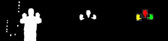
This block is used to draw a rectangular frame around the found object. Since the objects are implemented in the amount of 32, then the frame generators are also 32. All of them are connected in series and each of them has its own unique address. This address is the same as the object's address in the object memory of the Blob detector module. When reading data from a FIFO, the frame generator compares the address from the FIFO with its unique address and either loads the coordinates of the object to draw the frame into itself or skips them.
Further operation of the generator is rather trivial: the coordinates of this pixel come to the frame generator along with the pixel data, and the detector compares them with the loaded coordinates from the FIFO. If the incoming coordinates are within the loaded coordinates, then the color of the pixel changes to the color of the frame, otherwise the pixel remains unchanged.
Box generator code
Bounding box generator
module box_generator #( parameter BADDR = 5'd0, parameter COLOR = 16'hF8_00 ) ( input clk, input nRst, input [4:0] addr, input [40:0] data, input we, input [10:0] hcount, input [10:0] vcount, input [15:0] pixel_i, output wire [15:0] pixel_o ); reg [10:0] xs = 0,xe = 0,ys = 0,ye = 0; reg box_valid = 0; reg [15:0] pixel_r; wire addr_valid = (addr == BADDR) ? 1'b1 : 1'b0; always @(posedge clk or negedge nRst) if (!nRst) begin xs <= 11'd0; ys <= 11'd0; xe <= 11'd0; ye <= 11'd0; box_valid <= 1'b0; end else begin if (we && addr_valid) begin xs = data[39:30]; xe = data[29:20]; ys = data[19:10]; ye = data[9:0]; box_valid = data[40]; end end always @(*) begin if ((hcount >= xs && hcount <= xe) && (vcount == ys || vcount == ye)) begin pixel_r = COLOR; end else begin if ((hcount == xs || hcount == xe) && (vcount >= ys && vcount <= ye)) pixel_r = COLOR; else pixel_r = pixel_i; end end assign pixel_o = box_valid ? pixel_r : pixel_i; endmodule The insertion of 32 frame generators is sequentially performed using the generate operator. The output of each previous module is input to the following.
wire [15:0] box_out [0:`OBJ_LIMIT-1]; genvar i; generate for(i = 0; i < `OBJ_LIMIT; i = i + 1 ) begin : box_gen if (i == 0) begin box_generator #( .BADDR(i), .COLOR(`CL_RED) ) BOX_GEN ( .clk(pix_clk), .nRst(nRst), .addr(box_data[45:41]), .data(box_data[40:0]), .we(box_fifo_rd_en), .hcount(counter_x), .vcount(counter_y), .pixel_i({morph_out[7:3], morph_out[7:2], morph_out[7:3]}), .pixel_o(box_out[0]) ); end else begin box_generator #( .BADDR(i), .COLOR(`CL_RED) ) BOX_GEN ( .clk(pix_clk), .nRst(nRst), .addr(box_data[45:41]), .data(box_data[40:0]), .we(box_fifo_rd_en), .hcount(counter_x), .vcount(counter_y), .pixel_i(box_out[i-1]), .pixel_o(box_out[i]) ); end end ndgenerate The above blocks are connected as follows:
wire [9:0] run_start, run_end; wire row_end, frame_end, new_run; wire [21:0] run_fifo_data_o; wire run_fifo_full, run_fifo_empty, run_fifo_wr_en, run_fifo_rd_en; run_detector #( .RES_X(10'd320), .RES_Y(10'd240), .XOFFSET(10'd320), .YOFFSET(10'd0) ) RUN_DETECTOR ( .clk(pix_clk), .nRst(nRst), .data_valid(in_frame2), .data_in(&morph_out), .xi(counter_x), .yi(counter_y), .run_start(run_start), .run_end(run_end), .row_end(row_end), .frame_end(frame_end), .new_run(new_run), .rd_req(run_read_req) ); wire [10:0] run_fifo_rd_used, run_fifo_wr_used; wire run_fifo_rd_avail = |run_fifo_rd_used[10:2]; wire run_fifo_almost_full = &run_fifo_wr_used[9:2]; assign run_fifo_wr_en = (!run_fifo_almost_full && new_run) ? 1'b1: 1'b0; alt_fifo_22x512 RUN_FIFO ( .wrclk(pix_clk), .data({frame_end, row_end, run_start, run_end}), .aclr(~nRst), .rdreq(run_fifo_rd_en), .wrreq(run_fifo_wr_en), .rdempty(run_fifo_empty), .rdclk(clk), .wrfull(), .q(run_fifo_data_o), .rdusedw(run_fifo_rd_used), .wrusedw(run_fifo_wr_used) ); wire box_we; wire [47:0] box_data; wire [47:0] box_data_det; blob_detector #( .RES_X(10'd320), .RES_Y(10'd240) ) BLOB_DET ( .clk(clk), .nRst(nRst), // input RUN FIFO .fifo_empty(run_fifo_empty), .fifo_data(run_fifo_data_o), .fifo_rd_en(run_fifo_rd_en), // output boxes interface .we(box_we), .data_o(box_data_det) ); wire [7:0] box_fifo_rd_used, box_fifo_wr_used; wire box_fifo_rd_avail = |box_fifo_rd_used[7:0]; wire box_fifo_almost_full = &box_fifo_wr_used[6:2]; wire box_fifo_wr_en = (box_we && !box_fifo_almost_full) ? 1'b1 : 1'b0; // read object FIFO right after valid first screen (this might be done anywhere within a frame) wire obj_read_ena = ((counter_y == 11'd0) && (counter_x < 10'd32)) ? 1'b1 : 1'b0; wire box_fifo_rd_en = box_fifo_rd_avail && obj_read_ena; dcfifo_41x128 BOX_FIFO ( .aclr(~nRst), .data(box_data_det), .rdclk(pix_clk), .rdreq(box_fifo_rd_en), .wrclk(clk), .wrreq(box_fifo_wr_en), .q(box_data), .rdempty(), .rdusedw(box_fifo_rd_used), .wrfull(), .wrusedw(box_fifo_wr_used) ); results
The result of the work of the detector of multiple objects is presented in this video:
findings
The resulting multi-object detector is scalable. To work with large resolutions of the input image, there is a possibility of increasing the number of detected objects by increasing the memory capacity of objects and RUNs.
Materials on the topic
→ Donald G. Bailey Design for Embedded Image Processing on FPGAs
→ Real-Time Blob Analysis Using the Run Length Encoding → FPGA
→ A Resource-Efficient Hardware Architecture for Connected Components Analysis
Source: https://habr.com/ru/post/327162/
All Articles