Recovering data from a damaged RAID 50 array
Many companies require servers with a high-performance disk subsystem of large capacity, which is achieved through the use of a large number of high-performance disks. We have a case when the company used a solution of 10 HDDs with a SAS interface with a capacity of 600 GB, organized into a RAID 50 array (the usable capacity of the array is 600 * 8 = 4800 GB). This RAID 50 is a combined array, which is considered as two RAID 5 arrays combined into a RAID 0 array. This solution allows you to get a higher write speed on the array compared to a regular RAID 5 with the same number of participating disks, because the formation of a parity block requires a smaller number of read operations from the disks of the participants (the speed of calculating the parity block itself can be neglected due to the fact that it represents a very small load for modern RAID controllers). Also in RAID 50, in some cases, fault tolerance will be higher, since it is possible to lose up to two drives (provided that drives from different RAID 5 arrays included in this RAID). In our case, according to the system administrator, 2 drives failed, which caused the RAID array to stop. This was followed by the actions of the system administrator and the service department of the server vendor company, which cannot be described due to confusing and contradictory testimony.
In our case, the disks are numbered by the customer’s representative from 0 to 9 with the words: “in that order they were used in the array, and no one changed them in some places”. This statement is subject to mandatory verification. We were also informed that this array was used as storage for the ESXi server, and it should contain several dozen virtual machines.
Before you start any operations on disks from an array, you need to check their physical integrity and operability, as well as create copies and continue to work exclusively with copies for safe work. If there are seriously damaged drives, consider the need to perform data extraction, that is, if only one drive is seriously damaged, it is necessary to find out by analyzing the array collected from the remaining disks whether the problematic HDD contains up-to-date data, or if they need to be ignored. XOR account operations over the remaining members of one of the RAID 5 that included this drive.
Copies were created, as a result of which it turned out that 4 drives have defects between LBA 424,000,000 and LBA 425,000,000, which is expressed in the form of unreadable several dozen sectors on each of the problematic disks. The unread sectors in the copies are filled with the pattern 0xDE 0xAD so that later there is the possibility of identifying the affected data.
')
The primary analysis involves identifying the RAID controller to which the disks were connected, more precisely identifying the location of the RAID controller metadata so that these areas do not include when assembled into an array.

In this case, in the last sector of each of the disks, we find the characteristic 0xDE 0x11 0xDE 0x11 with further marking of the brand of the RAID controller. The metadata of this controller is located solely at the end of the LBA range, any buffer zones in the middle of the range are not used by this controller. Based on this and previous data, the conclusion is that array collection should begin with LBA 0 of each of the disks.
Knowing that the total capacity of the array is more than 2 TB, we search LBA 0 for each disk in the partition table (protective MBR )

and GPT header in LBA 1.

In this case, these structures are not detected. These structures usually fall victim to the rash actions of server maintenance personnel who did not work out situations of storage system failure and did not study the specific features of the operation of a specific RAID controller.
For further analysis of the features of the array, it is necessary to search regular expressions of monotonically increasing sequences on one of the disks. These can be either FAT tables or a rather large MFT fragment, or other structures that are convenient for analysis. Knowing that this array contained Windows virtual machines, we can assume that the NTFS file system was used inside these machines. Based on this, we search for MFT records using the characteristic regular expression 0x46 0x49 0x4C 0x45 with zero offset from the 512-byte block (sector). In our case, after LBA 2,400,000 (1.2GB), a sufficiently long (more than 5000 records) MFT fragment is found. In our case, the MFT record size is standard and is 1024 bytes (2 sectors).

Localize the boundaries of the found fragment with MFT records and check for the presence of a fragment with MFT records in these boundaries on the remaining disks participating in the array (the boundaries may slightly differ, but not more than by the size of the block used in the RAID array). In our case, the presence of MFT records is confirmed. Scroll through the records with the analysis of numbers (the DWORD number is located at offset 0x2C). Analyze the number of blocks, where the increase in the number of MFT records occurs with a change of one, based on this, we calculate the size of the block used in this RAID array. In our case, the size is 0x10000 bytes (128 sectors or 64KiB). Next, choose among the MFT records any of the places where the MFT records or the result of their XOR operation are symmetrically located on all the participating disks and create a matrix with the record numbers from which the array blocks with double the number of rows begin.
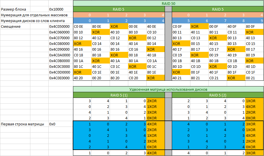
By record numbers, we will determine which of the disks are included in the first RAID 5, and which in the second. Checking the correctness is performed through the XOR operation. In our case, according to the table, we see that the numbering of the disks by the customer’s representative was done incorrectly, since the matrices of both arrays differ in the location of the parity block (denoted as “XOR”). We also see that in this array there is no parity delay, since the position of the parity block changes with each line.
By filling the table with MFT record numbers for the specified offsets from each of the disks, you can proceed to filling in the doubled disk usage matrix. It is doubled due to the fact that we started to form the matrix in an arbitrary place. The next task is to determine from which row the correct matrix begins. The task is easily accomplished if we take the first five offsets indicated in the figure above and multiply by 8. Next, solve a simple example in the form a = a + b where the starting values are a = 0x0 b = 0x280000 (0x280000 = 0x10000 * 0x28, where 0x28 is the number blocks with data that are contained in the disk usage matrix) and solve it in a loop until it reaches one of the offset values multiplied by 8.
After constructing the disk utilization matrix, we can produce an array by any means available for this, which can work with a matrix of arbitrary size. But such an array collection option will not take into account the relevance of data on all disks, and therefore additional analyzes are needed to exclude a disk containing irrelevant data (it was first excluded from the array).
Determining an irrelevant disk does not usually require a complete array collection. It is enough to collect the first 10-100GB and analyze the structures found. In our case, we operate with the beginning of an array of 20GB. As already written, the protective MBR and GPT are absent on the disks, and, of course, they are not in the assembled array, but when searching quite quickly you can find the magic VMFS block, taking away its position 0x100000 (2048 sectors), we get the beginning point of the VMFS partition. Having determined the position of fdc.sf (file descriptor system file), we will analyze its contents. In many cases, the analysis of this structure will allow to find a place where there are erroneous records. Comparing it with the disk usage matrix, we obtain the number of the disk containing irrelevant data. In our case, this turned out to be enough and no additional analytical measures were required.
By completing the entire array collection with compensation for missing data due to XOR operations, we obtained a complete array image. Knowing the localization of defects and the localization of virtual machine files in the image, it is possible to establish which particular virtual machine files are defective. After copying the virtual machine files from the VMFS storage, we can mount them in the OS as separate disks and check the integrity of the files contained in the virtual machines by searching for files containing sectors with the 0xDE 0xAD pattern. Having formed the list of damaged files, the work of recovering information from damaged RAID 50 can be considered completed.
I draw your attention to the fact that this publication does not intentionally mention professional data recovery systems that simplify the work of a specialist.
Next post: Restore 1C Enterprise (DBF) database after formatting.
In our case, the disks are numbered by the customer’s representative from 0 to 9 with the words: “in that order they were used in the array, and no one changed them in some places”. This statement is subject to mandatory verification. We were also informed that this array was used as storage for the ESXi server, and it should contain several dozen virtual machines.
Before you start any operations on disks from an array, you need to check their physical integrity and operability, as well as create copies and continue to work exclusively with copies for safe work. If there are seriously damaged drives, consider the need to perform data extraction, that is, if only one drive is seriously damaged, it is necessary to find out by analyzing the array collected from the remaining disks whether the problematic HDD contains up-to-date data, or if they need to be ignored. XOR account operations over the remaining members of one of the RAID 5 that included this drive.
Copies were created, as a result of which it turned out that 4 drives have defects between LBA 424,000,000 and LBA 425,000,000, which is expressed in the form of unreadable several dozen sectors on each of the problematic disks. The unread sectors in the copies are filled with the pattern 0xDE 0xAD so that later there is the possibility of identifying the affected data.
')
The primary analysis involves identifying the RAID controller to which the disks were connected, more precisely identifying the location of the RAID controller metadata so that these areas do not include when assembled into an array.
In this case, in the last sector of each of the disks, we find the characteristic 0xDE 0x11 0xDE 0x11 with further marking of the brand of the RAID controller. The metadata of this controller is located solely at the end of the LBA range, any buffer zones in the middle of the range are not used by this controller. Based on this and previous data, the conclusion is that array collection should begin with LBA 0 of each of the disks.
Knowing that the total capacity of the array is more than 2 TB, we search LBA 0 for each disk in the partition table (protective MBR )
and GPT header in LBA 1.
In this case, these structures are not detected. These structures usually fall victim to the rash actions of server maintenance personnel who did not work out situations of storage system failure and did not study the specific features of the operation of a specific RAID controller.
For further analysis of the features of the array, it is necessary to search regular expressions of monotonically increasing sequences on one of the disks. These can be either FAT tables or a rather large MFT fragment, or other structures that are convenient for analysis. Knowing that this array contained Windows virtual machines, we can assume that the NTFS file system was used inside these machines. Based on this, we search for MFT records using the characteristic regular expression 0x46 0x49 0x4C 0x45 with zero offset from the 512-byte block (sector). In our case, after LBA 2,400,000 (1.2GB), a sufficiently long (more than 5000 records) MFT fragment is found. In our case, the MFT record size is standard and is 1024 bytes (2 sectors).
Localize the boundaries of the found fragment with MFT records and check for the presence of a fragment with MFT records in these boundaries on the remaining disks participating in the array (the boundaries may slightly differ, but not more than by the size of the block used in the RAID array). In our case, the presence of MFT records is confirmed. Scroll through the records with the analysis of numbers (the DWORD number is located at offset 0x2C). Analyze the number of blocks, where the increase in the number of MFT records occurs with a change of one, based on this, we calculate the size of the block used in this RAID array. In our case, the size is 0x10000 bytes (128 sectors or 64KiB). Next, choose among the MFT records any of the places where the MFT records or the result of their XOR operation are symmetrically located on all the participating disks and create a matrix with the record numbers from which the array blocks with double the number of rows begin.
By record numbers, we will determine which of the disks are included in the first RAID 5, and which in the second. Checking the correctness is performed through the XOR operation. In our case, according to the table, we see that the numbering of the disks by the customer’s representative was done incorrectly, since the matrices of both arrays differ in the location of the parity block (denoted as “XOR”). We also see that in this array there is no parity delay, since the position of the parity block changes with each line.
By filling the table with MFT record numbers for the specified offsets from each of the disks, you can proceed to filling in the doubled disk usage matrix. It is doubled due to the fact that we started to form the matrix in an arbitrary place. The next task is to determine from which row the correct matrix begins. The task is easily accomplished if we take the first five offsets indicated in the figure above and multiply by 8. Next, solve a simple example in the form a = a + b where the starting values are a = 0x0 b = 0x280000 (0x280000 = 0x10000 * 0x28, where 0x28 is the number blocks with data that are contained in the disk usage matrix) and solve it in a loop until it reaches one of the offset values multiplied by 8.
After constructing the disk utilization matrix, we can produce an array by any means available for this, which can work with a matrix of arbitrary size. But such an array collection option will not take into account the relevance of data on all disks, and therefore additional analyzes are needed to exclude a disk containing irrelevant data (it was first excluded from the array).
Determining an irrelevant disk does not usually require a complete array collection. It is enough to collect the first 10-100GB and analyze the structures found. In our case, we operate with the beginning of an array of 20GB. As already written, the protective MBR and GPT are absent on the disks, and, of course, they are not in the assembled array, but when searching quite quickly you can find the magic VMFS block, taking away its position 0x100000 (2048 sectors), we get the beginning point of the VMFS partition. Having determined the position of fdc.sf (file descriptor system file), we will analyze its contents. In many cases, the analysis of this structure will allow to find a place where there are erroneous records. Comparing it with the disk usage matrix, we obtain the number of the disk containing irrelevant data. In our case, this turned out to be enough and no additional analytical measures were required.
By completing the entire array collection with compensation for missing data due to XOR operations, we obtained a complete array image. Knowing the localization of defects and the localization of virtual machine files in the image, it is possible to establish which particular virtual machine files are defective. After copying the virtual machine files from the VMFS storage, we can mount them in the OS as separate disks and check the integrity of the files contained in the virtual machines by searching for files containing sectors with the 0xDE 0xAD pattern. Having formed the list of damaged files, the work of recovering information from damaged RAID 50 can be considered completed.
I draw your attention to the fact that this publication does not intentionally mention professional data recovery systems that simplify the work of a specialist.
Next post: Restore 1C Enterprise (DBF) database after formatting.
Source: https://habr.com/ru/post/326930/
All Articles