TCP / IP basics for future dilettantes
Suppose that you have a poor knowledge of network technologies, and do not even know the elementary basics. But you have been given the task: in a short time to build an information network in a small enterprise. You have neither the time nor the desire to study thick Talmuds on network design, instructions on how to use network equipment and to delve into network security. And, most importantly, in the future you have no desire to become a professional in this field. Then this article is for you.
The second part of this article, which discusses the practical application of the fundamentals outlined here: Notes on Cisco Catalyst: VLAN setup, password reset, IOS operating system flashing
The task is to transfer information from point A to point B. It can be transmitted continuously. But the task becomes more complicated if it is necessary to transmit information between A <-> B and A <-> C points on the same physical channel. If the information is transmitted continuously, then when C wants to transmit information to A, he will have to wait until B finishes the transmission and releases the communication channel. This information transfer mechanism is very inconvenient and impractical. And to solve this problem, it was decided to divide the information into chunks.
')
At the recipient, these portions are required to be integrated, get the information that came from the sender. But on the recipient And now we see pieces of information from both B and C mixed together. This means that for each portion it is necessary to enter an identification number so that recipient A can distinguish portions of information from B from portions of information from C and collect these portions in the original message. Obviously, the recipient must know where and in what form the sender assigned identification data to the initial piece of information. And for this they must develop certain rules for the formation and writing of identification information. Further the word “rule” will be replaced by the word “protocol”.
To meet the needs of modern consumers, it is necessary to specify several types of identification information at once. And it also requires the protection of the transmitted portions of information from both random interference (during transmission over communication lines) and intentional sabotage (hacking). For this, a portion of the transmitted information is supplemented with a significant amount of special service information.
The Ethernet protocol contains the number of the network adapter of the sender (MAC address), the number of the network adapter of the recipient, the type of transmitted data and the directly transmitted data. A piece of information compiled according to the Ethernet protocol is called a frame. It is believed that network adapters with the same number does not exist. The network equipment extracts the transmitted data from the frame (hardware or software), and performs further processing.
As a rule, the extracted data, in turn, is formed in accordance with the IP protocol and have a different type of identification information - the recipient's ip address (a 4 byte number), the sender's ip address, and data. As well as many other necessary service information. The data generated by the IP protocol is called a packet.
Next, the data is extracted from the package. But this data, as a rule, is not yet the initially sent data. This piece of information is also compiled according to a specific protocol. The most widely used TCP protocol. It contains such identification information as the port of the sender (a two-byte number) and the source port, as well as data and service information. The extracted data from TCP, as a rule, is the data that the program running on computer B sent to the receiver program on computer A.
The complexity of the protocols (in this case, TCP over IP over Ethernet) is called a protocol stack.
There are networks of classes A, B, C, D and E. They differ in the number of computers and the number of possible networks / subnets in them. For simplicity, and as the most common case, we will consider only the class C network, whose ip-address starts at 192.168. The next number will be the subnet number, followed by the network equipment number. For example, a computer with an ip address of 192.168.30.110 wants to send information to another computer with the number 3 located on the same logical subnet. This means that the recipient's ip address will be: 192.168.30.3
It is important to understand that the information network node is a computer connected by one physical channel with switching equipment. Those. if we send the data from the network adapter "at will", then they have one way - they will come out from the other end of the twisted pair. We can send absolutely any data formed according to any rule that we invented, either by specifying either the ip address or the mac address or other attributes. And, if this other end is connected to another computer, we can accept them there and interpret them as necessary. But if this other end is connected to the switch, then in this case the information packet should be formed according to strictly defined rules, as if giving the switch instructions on what to do next with this packet. If the packet is formed correctly, the switch will send it further to another computer, as indicated in the packet. After that, the switch will remove this packet from its RAM. But if the package was not formed correctly, i.e. the instructions in it were incorrect, the package would “die”, i.e. the switch will not send it anywhere, but will immediately remove it from its RAM.
To transfer information to another computer, you need to specify three identification values in the information packet being sent - mac address, ip address and port. Relatively speaking, a port is a number that the operating system issues to each program that wants to send data to the network. Ip address of the recipient is entered by the user, or the program itself receives it, depending on the specifics of the program. The mac address remains unknown, i.e. the network adapter number of the recipient’s computer. To receive the necessary data, a “broadcast” request is sent, which is composed of the so-called “ARP Address Resolution Protocol”. Below is the structure of the ARP packet.

Now we do not need to know the values of all the fields in the above picture. Let's stop only on the main ones.
The fields contain the source ip address and destination ip address, as well as the source mac address.
The field “Ethernet destination address” is filled with units (ff: ff: ff: ff: ff: ff). Such an address is called a broadcast, and such a frame is sent to all “cable interfaces”, i.e. all computers connected to the switch.
The switch, having received such a broadcast frame, sends it to all computers on the network, as if addressing everyone with the question: “If you are the owner of this IP address (destination IP address), please tell me your mac address”. When another computer receives such an ARP request, it checks the destination ip address with its own. And if it matches, the computer inserts its mac address into the unit, swaps the ip and mac source and destination addresses, changes some service information and sends the packet back to the switch, and that one back to the original computer, the initiator of the ARP request.
This way, your computer recognizes the mac address of another computer to which you want to send data. If there are several computers on the network that respond to this ARP request, then we get a “IP address conflict”. In this case, you need to change the ip address on the computers so that the network does not have the same ip address.
In practice, as a rule, it is required to build a network, the number of computers in which will be at least one hundred. And besides the file sharing functions, our network must be safe and easy to manage. Thus, when building a network, there are three requirements:
Why does a large number of computers reduce network speed? - the reason is simple: due to the large number of broadcast messages (AL). AL is a message that, arriving at the switch, is sent to all network hosts. Or, roughly speaking, all computers on your subnet. If there are 5 computers in the network, then each computer will take 4 ALs. If there are 200 of them, then each computer in such a large network will take on 199 AL.
There are many applications, software modules and services that send broadcast messages to the network for their work. Described in the ARP clause: the protocol for determining the address is only one of the many zones that your computer sends to the network. For example, when you enter the “Network Neighborhood” (Windows OS), your computer sends several more ALs with special information generated using the NetBios protocol to scan the network for computers in the same workgroup. After that, the OS draws the found computers in the Network Neighborhood window and you see them.
It is also worth noting that during the scanning process by this or that program, your computer sends out no broadcast message, but several, for example, to establish virtual sessions with remote computers or for some other system needs caused by software problems. implementation of this application. Thus, each computer on the network has to send many different ALs to interact with other computers, thereby loading the communication channel with information that is not needed by the end user. As practice shows, in large networks, broadcast messages can make up a significant part of the traffic, thereby slowing down the work of the network visible to the user.
To solve the first and third problems, as well as to help solve the second problem, they everywhere use the mechanism of dividing the local network into smaller networks, as if separate Local Area Networks (Virtual Local Area Network). Basically, a VLAN is a list of ports on a switch that belong to the same network. “One” in the sense that the other VLAN will contain a list of ports belonging to another network.
In fact, creating two VLANs on one switch is equivalent to buying two switches, i.e. creating two VLANs is the same as splitting a switch into two. Thus, the network is divided from a hundred computers into smaller networks, from 5-20 computers - as a rule, this number corresponds to the physical location of computers as needed for file sharing.
Perhaps the phrase “it’s enough for the administrator to remove a port from one VLAN and add it to another” might not be clear, so I’ll explain it in more detail. In this case, the port is not a number provided by the OS to the application, as described in paragraph Stack of protocols, but a socket (place) where you can attach (insert) an RJ-45 format connector. Such a connector (i.e., a lug to the wire) is attached to both ends of an 8-core wire called a “twisted pair”. The figure shows a Cisco Catalyst 2950C-24 switch for 24 ports:
As mentioned in the ARP clause: the protocol for determining the address of each computer is connected to the network by one physical channel. Those. 24 computers can be connected to a 24-port switch. Twisted pair physically permeates all premises of the enterprise - all 24 wires from this switch are pulled into different cabinets. Let, for example, 17 wires go and connect to 17 computers in the audience, 4 wires go to the special department office and the remaining 3 wires go to the newly renovated, new accounting office. And the accountant Lida, for special merits, was transferred to this very office.
As mentioned above, VLANs can be represented as a list of ports belonging to a network. For example, our switch had three VLANs, i.e. three lists stored in switch flash memory. The numbers 1, 2, 3 ... 17 were written in one list, 18, 19, 20, 21 in the other, 22, 23 and 24 in the third. Lidin computer was previously connected to port 20. And so she moved to another office. They dragged her old computer to a new office, or she sat down at a new computer - no difference. The main thing is that her computer was connected with a twisted pair, the other end of which is inserted into port 23 of our switch. And in order that she could still send files to her colleagues from her new place, the administrator must delete the number 20 from the second list and add the number 23. I note that one port can belong to only one VLAN, but we will break this rule at the end of this paragraph.
I note also that when changing the port membership in the VLAN, the administrator does not need to “poke” the wires in the switch. Moreover, he does not even have to get up from his seat. Because the administrator's computer is connected to port 22, with which it can control the switch remotely. Of course, thanks to the special settings that will be discussed later, only the administrator can manage the switch. For information on how to configure VLANs, read VLANs, practice [in the next article].
As you probably noticed, initially (in the item Networking) I said that there would be at least 100 computers in our network. But only 24 computers can be connected to the switchboard. Of course, there are switches with a large number of ports. But there are still more computers in the corporate / enterprise network. And in order to connect an infinitely large number of computers to a network, they interconnect switches through a so-called trunk port (trunk). When you configure the switch, any of the 24-ports can be defined as a trunk port. And the trunk ports on the switch can be any number (but it is reasonable to do no more than two). If one of the ports is defined as trunk, the switch generates all the information that came to it into special packets, using the ISL or 802.1Q protocol, and sends these packets to the trunk port.
All the information that came in - I mean, all the information that came to him from the other ports. And the 802.1Q protocol is inserted into the protocol stack between Ethernet and the protocol on which the generated data was carried that carries this frame.
In this example, as you probably noticed, the administrator is sitting in the same office with Lida, because Twisted time from ports 22, 23 and 24 leads to the same cabinet. The 24th port is configured as a trunk port. And the switch itself is located in the back room, next to the old accountant’s office and with an audience of 17 computers.
Twisted pair, which goes from port 24 to the office to the administrator, connects to another switch, which in turn is connected to the router, which will be discussed in the following chapters. Other switches that connect the other 75 computers and are located in other back rooms of the enterprise - they all, as a rule, have one trunk port connected by a twisted pair or fiber to the main switch, which is in the office with the administrator.
It was said above that it is sometimes wise to make two trunk ports. The second trunk port is then used to analyze network traffic.
Approximately it looked like the construction of networks of large enterprises at the time of the Cisco Catalyst 1900 switch. You probably noticed two big inconveniences of such networks. First, the use of a trunk port causes some difficulties and creates extra work when configuring equipment. And secondly, and most importantly - suppose that our “like networks” of accountants, economists and dispatchers want to have one for three databases. They want the same accountant to see the changes in the database that the economist or dispatcher made a few minutes ago. To do this, we need to make a server that will be available to all three networks.
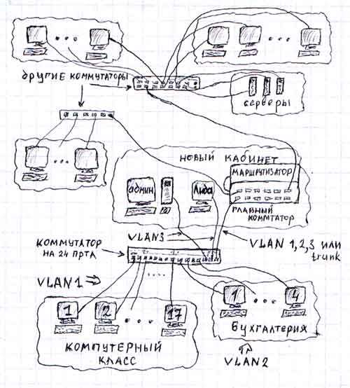
As mentioned in the middle of this point, a port can only be in one VLAN. And this is true, however, only for Cisco Catalyst 1900 and older series switches and for some younger models, such as Cisco Catalyst 2950. For other switches, in particular Cisco Catalyst 2900XL, this rule can be broken. When configuring ports in such switches, each time can have five modes of operation: Static Access, Multi-VLAN, Dynamic Access, ISL Trunk and 802.1Q Trunk. The second mode of operation is exactly what we need for the above task - to give access to the server from three networks at once, i.e. make the server belong to three networks at the same time. This is also called intersection or tagging of VLANs. In this case, the connection scheme may be as follows:
The second part of this article, which discusses the practical application of the fundamentals outlined here: Notes on Cisco Catalyst: VLAN setup, password reset, IOS operating system flashing
The article was tested on real students. I let them read part of the article and evaluate for clarity. Then he edited and simplified the material until it became clear even to the most inveterate Losers.
The second part of this article, which discusses the practical application of the fundamentals outlined here: Notes on Cisco Catalyst: VLAN setup, password reset, IOS operating system flashing
The concept of the protocol stack
The task is to transfer information from point A to point B. It can be transmitted continuously. But the task becomes more complicated if it is necessary to transmit information between A <-> B and A <-> C points on the same physical channel. If the information is transmitted continuously, then when C wants to transmit information to A, he will have to wait until B finishes the transmission and releases the communication channel. This information transfer mechanism is very inconvenient and impractical. And to solve this problem, it was decided to divide the information into chunks.
')
At the recipient, these portions are required to be integrated, get the information that came from the sender. But on the recipient And now we see pieces of information from both B and C mixed together. This means that for each portion it is necessary to enter an identification number so that recipient A can distinguish portions of information from B from portions of information from C and collect these portions in the original message. Obviously, the recipient must know where and in what form the sender assigned identification data to the initial piece of information. And for this they must develop certain rules for the formation and writing of identification information. Further the word “rule” will be replaced by the word “protocol”.
To meet the needs of modern consumers, it is necessary to specify several types of identification information at once. And it also requires the protection of the transmitted portions of information from both random interference (during transmission over communication lines) and intentional sabotage (hacking). For this, a portion of the transmitted information is supplemented with a significant amount of special service information.
The Ethernet protocol contains the number of the network adapter of the sender (MAC address), the number of the network adapter of the recipient, the type of transmitted data and the directly transmitted data. A piece of information compiled according to the Ethernet protocol is called a frame. It is believed that network adapters with the same number does not exist. The network equipment extracts the transmitted data from the frame (hardware or software), and performs further processing.
As a rule, the extracted data, in turn, is formed in accordance with the IP protocol and have a different type of identification information - the recipient's ip address (a 4 byte number), the sender's ip address, and data. As well as many other necessary service information. The data generated by the IP protocol is called a packet.
Next, the data is extracted from the package. But this data, as a rule, is not yet the initially sent data. This piece of information is also compiled according to a specific protocol. The most widely used TCP protocol. It contains such identification information as the port of the sender (a two-byte number) and the source port, as well as data and service information. The extracted data from TCP, as a rule, is the data that the program running on computer B sent to the receiver program on computer A.
The complexity of the protocols (in this case, TCP over IP over Ethernet) is called a protocol stack.
ARP: Address Resolution Protocol
There are networks of classes A, B, C, D and E. They differ in the number of computers and the number of possible networks / subnets in them. For simplicity, and as the most common case, we will consider only the class C network, whose ip-address starts at 192.168. The next number will be the subnet number, followed by the network equipment number. For example, a computer with an ip address of 192.168.30.110 wants to send information to another computer with the number 3 located on the same logical subnet. This means that the recipient's ip address will be: 192.168.30.3
It is important to understand that the information network node is a computer connected by one physical channel with switching equipment. Those. if we send the data from the network adapter "at will", then they have one way - they will come out from the other end of the twisted pair. We can send absolutely any data formed according to any rule that we invented, either by specifying either the ip address or the mac address or other attributes. And, if this other end is connected to another computer, we can accept them there and interpret them as necessary. But if this other end is connected to the switch, then in this case the information packet should be formed according to strictly defined rules, as if giving the switch instructions on what to do next with this packet. If the packet is formed correctly, the switch will send it further to another computer, as indicated in the packet. After that, the switch will remove this packet from its RAM. But if the package was not formed correctly, i.e. the instructions in it were incorrect, the package would “die”, i.e. the switch will not send it anywhere, but will immediately remove it from its RAM.
To transfer information to another computer, you need to specify three identification values in the information packet being sent - mac address, ip address and port. Relatively speaking, a port is a number that the operating system issues to each program that wants to send data to the network. Ip address of the recipient is entered by the user, or the program itself receives it, depending on the specifics of the program. The mac address remains unknown, i.e. the network adapter number of the recipient’s computer. To receive the necessary data, a “broadcast” request is sent, which is composed of the so-called “ARP Address Resolution Protocol”. Below is the structure of the ARP packet.
Now we do not need to know the values of all the fields in the above picture. Let's stop only on the main ones.
The fields contain the source ip address and destination ip address, as well as the source mac address.
The field “Ethernet destination address” is filled with units (ff: ff: ff: ff: ff: ff). Such an address is called a broadcast, and such a frame is sent to all “cable interfaces”, i.e. all computers connected to the switch.
The switch, having received such a broadcast frame, sends it to all computers on the network, as if addressing everyone with the question: “If you are the owner of this IP address (destination IP address), please tell me your mac address”. When another computer receives such an ARP request, it checks the destination ip address with its own. And if it matches, the computer inserts its mac address into the unit, swaps the ip and mac source and destination addresses, changes some service information and sends the packet back to the switch, and that one back to the original computer, the initiator of the ARP request.
This way, your computer recognizes the mac address of another computer to which you want to send data. If there are several computers on the network that respond to this ARP request, then we get a “IP address conflict”. In this case, you need to change the ip address on the computers so that the network does not have the same ip address.
Networking
The task of building networks
In practice, as a rule, it is required to build a network, the number of computers in which will be at least one hundred. And besides the file sharing functions, our network must be safe and easy to manage. Thus, when building a network, there are three requirements:
- Easy to manage. If the accountant Lida is transferred to another office, she will still need access to the computers of accountants Anna and Yulia. And with the wrong construction of its information network, the administrator may have difficulty in issuing Lida access to the computers of other accountants in her new place.
- Security. To ensure the security of our network, access rights to information resources should be delimited. Also, the network must be protected from threats of disclosure, integrity, and denial of service. Read more in the book “Attack on the Internet” by the author Ilya Davidovich Medvedovsky, chapter “Basic concepts of computer security” .
- Network performance. When building networks, there is a technical problem - the dependence of the transfer rate on the number of computers in the network. The more computers - the lower the speed. With a large number of computers, the network performance can become so low that it becomes unacceptable to the customer.
Why does a large number of computers reduce network speed? - the reason is simple: due to the large number of broadcast messages (AL). AL is a message that, arriving at the switch, is sent to all network hosts. Or, roughly speaking, all computers on your subnet. If there are 5 computers in the network, then each computer will take 4 ALs. If there are 200 of them, then each computer in such a large network will take on 199 AL.
There are many applications, software modules and services that send broadcast messages to the network for their work. Described in the ARP clause: the protocol for determining the address is only one of the many zones that your computer sends to the network. For example, when you enter the “Network Neighborhood” (Windows OS), your computer sends several more ALs with special information generated using the NetBios protocol to scan the network for computers in the same workgroup. After that, the OS draws the found computers in the Network Neighborhood window and you see them.
It is also worth noting that during the scanning process by this or that program, your computer sends out no broadcast message, but several, for example, to establish virtual sessions with remote computers or for some other system needs caused by software problems. implementation of this application. Thus, each computer on the network has to send many different ALs to interact with other computers, thereby loading the communication channel with information that is not needed by the end user. As practice shows, in large networks, broadcast messages can make up a significant part of the traffic, thereby slowing down the work of the network visible to the user.
VLANs
To solve the first and third problems, as well as to help solve the second problem, they everywhere use the mechanism of dividing the local network into smaller networks, as if separate Local Area Networks (Virtual Local Area Network). Basically, a VLAN is a list of ports on a switch that belong to the same network. “One” in the sense that the other VLAN will contain a list of ports belonging to another network.
In fact, creating two VLANs on one switch is equivalent to buying two switches, i.e. creating two VLANs is the same as splitting a switch into two. Thus, the network is divided from a hundred computers into smaller networks, from 5-20 computers - as a rule, this number corresponds to the physical location of computers as needed for file sharing.
- When a network is divided into VLANs, it is easy to manage. So, when the accountant Lida goes to another room, the administrator simply removes the port from one VLAN and adds it to another. This is discussed in more detail in VLANs, theory.
- VLANs help solve one of the network security requirements, namely the delimitation of network resources. Thus, a student from one audience will not be able to penetrate the computers of another audience or the rector's computer, since they are in actually different networks.
- Since our network is divided into VLANs, i.e. On small "like networks", the problem with broadcast messages disappears.
VLANs, theory
Perhaps the phrase “it’s enough for the administrator to remove a port from one VLAN and add it to another” might not be clear, so I’ll explain it in more detail. In this case, the port is not a number provided by the OS to the application, as described in paragraph Stack of protocols, but a socket (place) where you can attach (insert) an RJ-45 format connector. Such a connector (i.e., a lug to the wire) is attached to both ends of an 8-core wire called a “twisted pair”. The figure shows a Cisco Catalyst 2950C-24 switch for 24 ports:
As mentioned in the ARP clause: the protocol for determining the address of each computer is connected to the network by one physical channel. Those. 24 computers can be connected to a 24-port switch. Twisted pair physically permeates all premises of the enterprise - all 24 wires from this switch are pulled into different cabinets. Let, for example, 17 wires go and connect to 17 computers in the audience, 4 wires go to the special department office and the remaining 3 wires go to the newly renovated, new accounting office. And the accountant Lida, for special merits, was transferred to this very office.
As mentioned above, VLANs can be represented as a list of ports belonging to a network. For example, our switch had three VLANs, i.e. three lists stored in switch flash memory. The numbers 1, 2, 3 ... 17 were written in one list, 18, 19, 20, 21 in the other, 22, 23 and 24 in the third. Lidin computer was previously connected to port 20. And so she moved to another office. They dragged her old computer to a new office, or she sat down at a new computer - no difference. The main thing is that her computer was connected with a twisted pair, the other end of which is inserted into port 23 of our switch. And in order that she could still send files to her colleagues from her new place, the administrator must delete the number 20 from the second list and add the number 23. I note that one port can belong to only one VLAN, but we will break this rule at the end of this paragraph.
I note also that when changing the port membership in the VLAN, the administrator does not need to “poke” the wires in the switch. Moreover, he does not even have to get up from his seat. Because the administrator's computer is connected to port 22, with which it can control the switch remotely. Of course, thanks to the special settings that will be discussed later, only the administrator can manage the switch. For information on how to configure VLANs, read VLANs, practice [in the next article].
As you probably noticed, initially (in the item Networking) I said that there would be at least 100 computers in our network. But only 24 computers can be connected to the switchboard. Of course, there are switches with a large number of ports. But there are still more computers in the corporate / enterprise network. And in order to connect an infinitely large number of computers to a network, they interconnect switches through a so-called trunk port (trunk). When you configure the switch, any of the 24-ports can be defined as a trunk port. And the trunk ports on the switch can be any number (but it is reasonable to do no more than two). If one of the ports is defined as trunk, the switch generates all the information that came to it into special packets, using the ISL or 802.1Q protocol, and sends these packets to the trunk port.
All the information that came in - I mean, all the information that came to him from the other ports. And the 802.1Q protocol is inserted into the protocol stack between Ethernet and the protocol on which the generated data was carried that carries this frame.
In this example, as you probably noticed, the administrator is sitting in the same office with Lida, because Twisted time from ports 22, 23 and 24 leads to the same cabinet. The 24th port is configured as a trunk port. And the switch itself is located in the back room, next to the old accountant’s office and with an audience of 17 computers.
Twisted pair, which goes from port 24 to the office to the administrator, connects to another switch, which in turn is connected to the router, which will be discussed in the following chapters. Other switches that connect the other 75 computers and are located in other back rooms of the enterprise - they all, as a rule, have one trunk port connected by a twisted pair or fiber to the main switch, which is in the office with the administrator.
It was said above that it is sometimes wise to make two trunk ports. The second trunk port is then used to analyze network traffic.
Approximately it looked like the construction of networks of large enterprises at the time of the Cisco Catalyst 1900 switch. You probably noticed two big inconveniences of such networks. First, the use of a trunk port causes some difficulties and creates extra work when configuring equipment. And secondly, and most importantly - suppose that our “like networks” of accountants, economists and dispatchers want to have one for three databases. They want the same accountant to see the changes in the database that the economist or dispatcher made a few minutes ago. To do this, we need to make a server that will be available to all three networks.
As mentioned in the middle of this point, a port can only be in one VLAN. And this is true, however, only for Cisco Catalyst 1900 and older series switches and for some younger models, such as Cisco Catalyst 2950. For other switches, in particular Cisco Catalyst 2900XL, this rule can be broken. When configuring ports in such switches, each time can have five modes of operation: Static Access, Multi-VLAN, Dynamic Access, ISL Trunk and 802.1Q Trunk. The second mode of operation is exactly what we need for the above task - to give access to the server from three networks at once, i.e. make the server belong to three networks at the same time. This is also called intersection or tagging of VLANs. In this case, the connection scheme may be as follows:
To be continued
The second part of this article, which discusses the practical application of the fundamentals outlined here: Notes on Cisco Catalyst: VLAN setup, password reset, IOS operating system flashing
About this article
The article was tested on real students. I let them read part of the article and evaluate for clarity. Then he edited and simplified the material until it became clear even to the most inveterate Losers.
Source: https://habr.com/ru/post/326574/
All Articles