Primitives for implementing 1-Wire master using PWM and ICP for STM8L and STM32
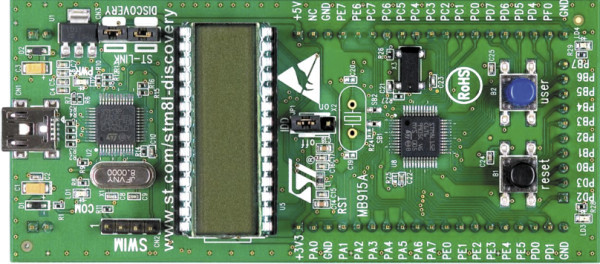
In the previous article , a variant of the implementation of primitives for asynchronous operation with a 1-wire bus for Atmel microcontrollers was presented. Well, now your attention is invited to the implementation of the same, but on more powerful microcontrollers of the STM8L family (for debugging, the usual STM8L-Discovery evaluation board with an extracted LCD display was used). With minimal changes, the described implementation can be adapted for the STM32 family.
IAR Embedded Workbench for STM8 with a free license was used as a toolchain (code size limit is 8Kb).
The 1-Wire bus driver is taken from the previous article. Connection is as follows:
')
Do not forget to connect GND, power + 5V and power + 3V3.
Unlike the AVR, the STM8 (and STM32) microcontrollers offer a wider range of internal peripherals. Thus, the described project can be compiled in several ways:
In addition, due to the PWM prohibition (BREAK-signal) input timers, it is possible to implement hardware protection against an attempt to perform data exchange at the moment of active-pullup enabled (i.e., so that they do not accidentally close the 1-wire to ground at the moment when it is powered to perform transformations).
General implementation features
When primitives are not used, the output of PB1 is kept low (i.e. the modulating stage is not active). The timer is programmed in such a way that the period duration corresponds to the timeslot duration plus the duration of the protective pause between bits (for the bit transmission procedure) or the total RESET pulse duration, the pause before the possible PRESENCE start and the maximum PRESENCE duration (for the RESET procedure).
The PWM control registers (TIMx_CCR1) and Capture (TIMx_CCR2) are programmed to use shadow registers. This means that after a programmatic change of the PWM register ((TIMx_CCR1), its value will be used only after the appearance of the UEV signal inside the microcontroller. And this signal is generated either automatically when the counter reaches the specified vertex (period) or programmatically by setting the UG bit in the TIMx_EGR register) .
Immediately before starting the PWM, the required pulse width of the lowest transmitted bit is calculated and loaded into the PWM register (TIMx_CCR1). After that, the timer is started by setting the CEN bit in the TIMx_CR1 register. At this moment, the PWM signal is not yet active, since The MOE bit in the TIMn_BKR register was previously reset to 0. After this, the UG bit is programmatically set to TIMx_EGR, which causes activation of the internal signal UEV, resetting the current counter value to 0 and loading the contents of the PWM register (TIMx_CCR1) into its shadow copy used for comparison .
In addition, since the AOE bit was set in advance in the TIMn_BKR register, the MOE bit in the TIMn_BKR register can be automatically set by the UEV signal, which will enable the PWM output. However, this will happen only when the BREAK signal is not active, which is generated from controlling external active-pullup (this is possible because the BREAK signal inside the microcontroller is formed directly from the signal value on the external pin, regardless of whether it is programmed for input or output mode) . Thus, if during the RESET procedure or when attempting to transmit / receive bit (s), the active-pullup signal is active, the activation of the PWM output will be blocked.
The principle of the IRQ-only implementation is the same as described in the previous article with the difference that instead of the up-down timer mode, the up-to-specified value count mode is used. This became possible because the bits of the 16-bit timer is enough for both the formation of a one-time transfer time slot period and the implementation of the “RESET signal generation with PRESENCE waiting” procedure.
In this implementation, the calculation of the duration of the next pulse is performed during the processing of an interrupt that occurs at the moment when the transmission of the previous bit is completed.
The implementation using DMA with 8-bit and 16- bit transmissions is basically the same and differs only in the bitness of the values for PWM and ICP. All pulse durations are calculated in advance before the timer starts. The low-order pulse width is loaded into the PWM register (TIMx_CCR1) as described above, and the 1st DMA channel is programmed to load the remaining values, if necessary. All measurement results are always saved using the 2nd DMA channel.
The generated code fits into the limit of the free license from IAR, therefore, having on hand an estimated fee, you can immediately begin to experiment. And, thanks to the possibility of hardware debugging, you can also study the features of the microcontroller's periphery functioning.
Note.
In the source code you can find a couple of high-level procedures for implementing the exchange protocol on the 1-Wire bus. They are quite working, but are excluded from the project by conditional compilation directives. Wait for the continuation of the use of pthreads and the asynchronous implementation of the high-level part of the protocol.
Bibliography:
IAR Embedded Workbench for STM8 with a free license was used as a toolchain (code size limit is 8Kb).
The 1-Wire bus driver is taken from the previous article. Connection is as follows:
')
- Contact PB1 of the evaluation board is connected to the OCRA driver.
- contact PD0 of the evaluation board is connected to the ICP driver
- Contact PA5 evaluation board connect to PULLUP driver
Do not forget to connect GND, power + 5V and power + 3V3.
Unlike the AVR, the STM8 (and STM32) microcontrollers offer a wider range of internal peripherals. Thus, the described project can be compiled in several ways:
- IRQ-only. The logic of work is implemented only by interrupt, without using DMA. This option is compiled when the symbol __DRV_ONEWIRE_DMA is not defined.
Pros of implementation:- Only 3 bytes of RAM required
- The ability to program a timer for any desired resolution
Cons of implementation:- A large number of interrupts (3 interrupts for each transmitted bit)
- DMA with 8-bit transmission. Timer programming and saving of results during the reception and transmission of bits is performed using DMA. This option is compiled when the symbol __DRV_ONEWIRE_DMA = 1.
Pros of implementation:- Requires 9 bytes of RAM
- A small number of interrupts (one interrupt on the 1st transmitted bit and 3 interrupts in case of successful completion of the exchange)
Cons of implementation:- The inability to program a timer for high resolution
- DMA with 16-bit transmission. The timer is programmed and the results are saved during the reception and transmission of bits using DMA. This option is compiled when the symbol __DRV_ONEWIRE_DMA = 2.
Pros of implementation:- A small number of interrupts (one interrupt on the 1st transmitted bit and 3 interrupts in case of successful completion of the exchange)
- The ability to program a timer for any desired resolution
Cons of implementation:- 17 bytes of RAM required
In addition, due to the PWM prohibition (BREAK-signal) input timers, it is possible to implement hardware protection against an attempt to perform data exchange at the moment of active-pullup enabled (i.e., so that they do not accidentally close the 1-wire to ground at the moment when it is powered to perform transformations).
General implementation features
When primitives are not used, the output of PB1 is kept low (i.e. the modulating stage is not active). The timer is programmed in such a way that the period duration corresponds to the timeslot duration plus the duration of the protective pause between bits (for the bit transmission procedure) or the total RESET pulse duration, the pause before the possible PRESENCE start and the maximum PRESENCE duration (for the RESET procedure).
The PWM control registers (TIMx_CCR1) and Capture (TIMx_CCR2) are programmed to use shadow registers. This means that after a programmatic change of the PWM register ((TIMx_CCR1), its value will be used only after the appearance of the UEV signal inside the microcontroller. And this signal is generated either automatically when the counter reaches the specified vertex (period) or programmatically by setting the UG bit in the TIMx_EGR register) .
Immediately before starting the PWM, the required pulse width of the lowest transmitted bit is calculated and loaded into the PWM register (TIMx_CCR1). After that, the timer is started by setting the CEN bit in the TIMx_CR1 register. At this moment, the PWM signal is not yet active, since The MOE bit in the TIMn_BKR register was previously reset to 0. After this, the UG bit is programmatically set to TIMx_EGR, which causes activation of the internal signal UEV, resetting the current counter value to 0 and loading the contents of the PWM register (TIMx_CCR1) into its shadow copy used for comparison .
In addition, since the AOE bit was set in advance in the TIMn_BKR register, the MOE bit in the TIMn_BKR register can be automatically set by the UEV signal, which will enable the PWM output. However, this will happen only when the BREAK signal is not active, which is generated from controlling external active-pullup (this is possible because the BREAK signal inside the microcontroller is formed directly from the signal value on the external pin, regardless of whether it is programmed for input or output mode) . Thus, if during the RESET procedure or when attempting to transmit / receive bit (s), the active-pullup signal is active, the activation of the PWM output will be blocked.
The principle of the IRQ-only implementation is the same as described in the previous article with the difference that instead of the up-down timer mode, the up-to-specified value count mode is used. This became possible because the bits of the 16-bit timer is enough for both the formation of a one-time transfer time slot period and the implementation of the “RESET signal generation with PRESENCE waiting” procedure.
In this implementation, the calculation of the duration of the next pulse is performed during the processing of an interrupt that occurs at the moment when the transmission of the previous bit is completed.
The implementation using DMA with 8-bit and 16- bit transmissions is basically the same and differs only in the bitness of the values for PWM and ICP. All pulse durations are calculated in advance before the timer starts. The low-order pulse width is loaded into the PWM register (TIMx_CCR1) as described above, and the 1st DMA channel is programmed to load the remaining values, if necessary. All measurement results are always saved using the 2nd DMA channel.
The generated code fits into the limit of the free license from IAR, therefore, having on hand an estimated fee, you can immediately begin to experiment. And, thanks to the possibility of hardware debugging, you can also study the features of the microcontroller's periphery functioning.
Note.
In the source code you can find a couple of high-level procedures for implementing the exchange protocol on the 1-Wire bus. They are quite working, but are excluded from the project by conditional compilation directives. Wait for the continuation of the use of pthreads and the asynchronous implementation of the high-level part of the protocol.
Bibliography:
Source: https://habr.com/ru/post/326114/
All Articles