These mysterious capacitors
This article is about the features of ceramic capacitors that appear at high frequencies (of the order of tens, hundreds of megahertz and higher). The article is based on research materials conducted by specialists at Johanson Technology.
This mainly focuses on ceramic capacitors suitable for use in:
- High-speed digital devices (filtering of its own and external interference);
- High-frequency devices (filtering, HF matching, RF signal processing, etc.);
- Any other devices for filtering external high-frequency interference, which can come both through the power supply circuit and through the air from wireless devices and systems, radio stations, power electronics devices, etc.
In the production of such capacitors, special dielectrics are used, which are called NPO or COG . These dielectrics are known to provide a weak dependence of the capacitor capacitance on the ambient temperature and the applied voltage.
Most often, to reduce the size, ceramic capacitors are made in the form of multilayer ceramic capacitors - MLCC, Multilayer Ceramic Capacitor , the structure of which is shown in the following picture:

')
One of the world leaders in the production of high-frequency ceramic capacitors is the company Johanson Technology , the materials of which served as the basis for this article.
What happens to capacitors as the frequency increases?
With an increase in the operating frequency of the first "special" frequency encountered by the researchers, is the serial resonance frequency - SRF, Series Resonant Frequency . As is known from the physics course, this is the frequency at which the reactance of an ideal capacitor is compensated for by the reactance of a series-connected ideal inductor in such a way that the total resistance of the circuit becomes zero. In the case of a ceramic capacitor, the phenomenon of series resonance is explained by the presence of parasitic inductance of the capacitor leads and plates. And the SRF is remarkable in our case as follows:
- At the frequency of series resonance (SRF) the capacitor has the lowest resistance, called equivalent series resistance - ESR, Equivalent Series Resistance . This fact allows instead of a capacitor to get a narrow-band filter that can be used to filter out noise.
- At frequencies higher than SRF, the capacitor behaves like an inductance! Therefore, it is sometimes said that at frequencies higher than the frequency of the series resonance, the capacitor is an inductance that does not let in a direct current - a DC blocking inductor .
With further increase in frequency, one can observe a number of frequencies at which the multilayer capacitor has a relatively high resistance. Such frequencies are called parallel resonance frequencies - PRF, Parallel Resonant Frequency . The presence of a series of parallel resonances is explained by the presence of parasitic capacitors connected in parallel with the DC blocking inductor.
It is interesting to note that in the general case, according to experimental data, a rough estimate of the frequency of the first parallel resonance can be obtained by doubling the value of the serial resonance frequency.
Another interesting fact is that you can get rid of all the odd frequencies of parallel resonance, including the first one, simply by arranging the plates of the inner plates of a multilayer capacitor not perpendicular to the surface of the printed circuit board, but perpendicular!
Look at an example of the dependence of the introduced attenuation on the frequency with two layouts of the plates, which Johanson leads:
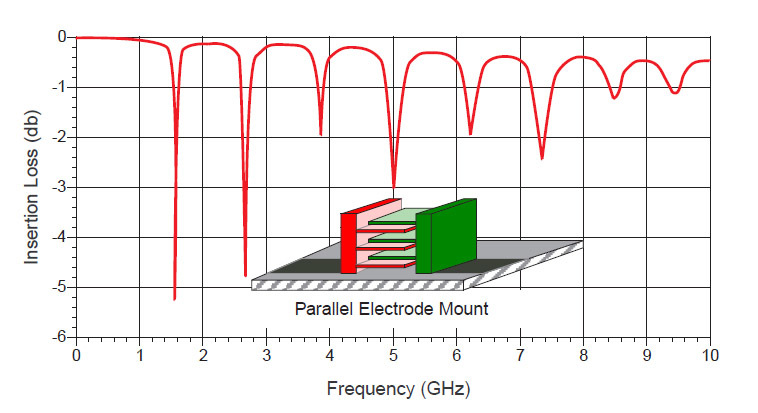
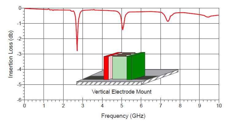
On the top picture, the capacitor plates are arranged parallel to the printed circuit board, and on the bottom - perpendicular.
It is assumed that the disappearance of the odd PRF frequencies is associated with a decrease in the parasitic capacitances between the plates of the ceramic capacitor and the printed circuit board. But why at the same time disappear odd resonances and remain even? If you have any thoughts on this, welcome to the comments!
Since the SRF and PRF frequencies of ceramic capacitors can lie in a very wide range, information about them becomes vital when designing electronic devices.
In its documentation, Johanson Technology gives the values of these frequencies, and the PRF frequency corresponds to the frequency of the first parallel resonance (capacitor plates are parallel to the board surface).
Here are typical resonant frequencies for Johanson Technology capacitors of size 0402:
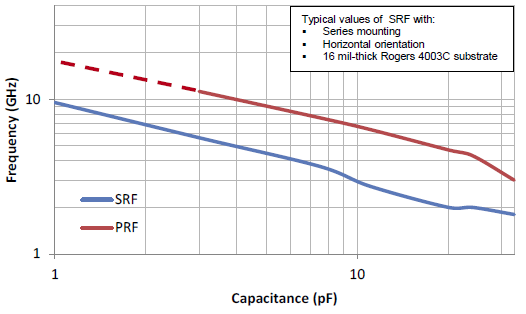
And typical values of resonant frequencies for Johanson Technology capacitors of size 0603:
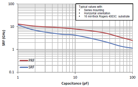
As you can see, the resonant frequencies move to lower frequencies with increasing capacitance and decreasing the size of capacitors. And this leads to a narrowing of the operating frequency range when it is necessary that this capacitor behaves like a ... capacitor!
Practical recommendations
- Carefully study the documentation for the used capacitors to eliminate the situation when the “correct” circuit does not work correctly.
- Do not use for filtering high-frequency noise low-frequency ceramic capacitors, capacitors with unknown characteristics (and even more so - electrolytic capacitors).
- Determine the frequency ranges of interference and select the filter capacitors, based on these ranges. Consider with this inductance of conductors, comparable to the parasitic inductance of high-frequency capacitors. To calculate the inductance of the conductor, you can use the formula:where L is the inductance, nH, x is the conductor length, cm, w is the conductor width, cm, h is the height of the conductor, see
- Follow the recommendations of manufacturers of electronic components regarding the rules of wiring high-frequency printed circuit boards.
- To extend the working range of the ceramic capacitor can be installed on its side (except for the first parallel resonance).
- In high-frequency circuits, the frequency of the series resonance of the capacitors used must be significantly higher than the operating frequency range. To consolidate this thought, Johanson Technology cites an example from their own experience, when, as the operating frequency approaches the serial resonance frequency, a 10 pF capacitor behaved like a 1000 pF capacitor!
If the device uses a wireless module Bluetooth, Wi-Fi, GSM, GPS, etc. with an external antenna, it is usually recommended to provide in the antenna circuit space for the installation of matching elements (placeholders). This allows, if necessary, to make a painless adjustment of the high-frequency part of the boards. To simplify this task, Johanson Technology proposes to use special high-frequency component cash registers , which make the process of matching RF circuits less time consuming.
Source: https://habr.com/ru/post/325952/
All Articles