Implementation of pseudo-3D in racing games
Introduction
Why pseudo-3d?
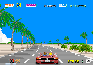
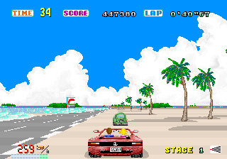
Why would anyone want to create roads in the old school style today, when every computer can draw graphics consisting of millions of polygons on the fly? Are polygons not the same, only better? Not really. Polygons do create less distortion, but it is the deformations in the old game engines that give such a surreal, dizzying sense of speed, felt in many additional poly games. Imagine that the scope is controlled by a camera. When moving along a curve in a game using one of these engines, it looks like it is looking at a curve. Then, when the road becomes straight, the view also straightens. When driving in a corner with a poor view, the camera seems to be looking behind the ledge. And since such games do not use the traditional format of tracks with exact spatial ratios, you can easily create tracks on which the player will ride at breathtaking speed. You do not need to worry about the fact that objects appear on the track faster than the player can react, because the physical reality of the game can be easily changed according to the gameplay style.
But in such a system there are many shortcomings. The depth of physics used in simulation games will be lost, so these engines are not adapted for these games. However, they are simple to implement, work fast, and games based on them are usually very interesting!
')
It is worth noting that not every old racing game uses these techniques. In fact, the method described in the article is only one of the ways to create a pseudo-three-dimensional road. In other cases, projected and scaled sprites or various ways of actually projecting the road are used. The degree of mixing real mathematics with tricks depends on the creators. I hope you enjoy exploring the special effect I proposed.
How well do you need to understand math?
If you…
... you know trigonometry, then it will be quite enough to understand the whole tutorial
... you know only algebra and geometry, then skip the “scope” explanation
... you want to avoid mathematical explanations, then read the sections “The Simplest Road”, “Curves and Turns”, “Sprites and Data” and “Hills”.
This is a universal technique, and you can understand in more detail simply by adding the appropriate sections. If you know complicated math, then you will be interested, but if you know only arithmetic, you can reach the level of detail created in games such as the Pole Position or the first OutRun.
How well do you need to know programming?
If you understand raster graphics, this will greatly help: it is enough to know what a scanline is, and that each line consists of a number of pixels. Examples of programs are written in pseudocode, so knowledge of a particular language is not required.
Ready? Let's get started!
Raster effects: short introduction
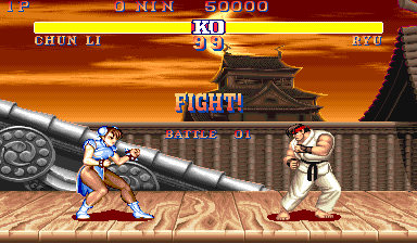
The pseudo-three-dimensional road is one of the cases of a more general class of effects, called raster effects. The most famous of the raster effects are used in Street Fighter II: when moving the fighters left or right, the surface of the earth changes in perspective. But this is not really 3D. Surface graphics are stored as a very wide angle shot. When scrolling, lines of the screen that are “farther away” move more slowly than closer ones. That is, each line on the screen moves independently of the other. Below is the final result and how the graphics of the earth's surface are stored in memory.

Basics of creating roads
Introduction to raster roads
We are accustomed to perceive 3D-effects in the framework of polygons, whose peaks are suspended in three-dimensional space. However, old computers were not powerful enough to cope with a large number of three-dimensional calculations. Therefore, raster effects were used most often in old games. These are special effects created by line-by-line change of a variable. This is well suited for the operation of old graphics hardware, which had hardware acceleration of scrolling and used the mode of indexed colors.
The pseudo-road raster effect was actually created in much the same way as the perspective effect in Street Fighter II, where the static image was deformed to add the illusion of three-dimensionality. Here is how it was implemented:
Most raster roads begin with a flat road image. In essence, this is a graphic depiction of two parallel lines on the ground, stretching into the distance. At distance, these lines seem to be connecting to the observer. This is the basic rule of perspective. In addition, to create the illusion of movement, most of the arcade racing games on the road were drawing stripes. The movement of these lanes on the road was achieved either by cyclically switching colors or changing the palette of each row. Curves and turns were performed by scrolling each line independently, as in Street Fighter II.
We will look at curves and turns in the next section. In the meantime, let's concentrate on scrolling the road forward.
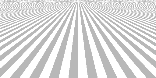
Simplest road
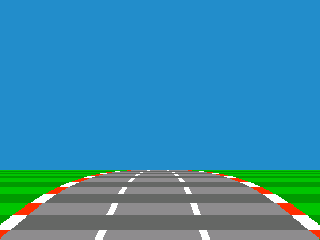
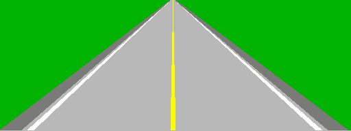
Take the image of the road described above: two parallel lines denoting the right and left side of the road, stretching into the distance. Moving away from the observer, they are getting closer. Here is an example of what this might look like:
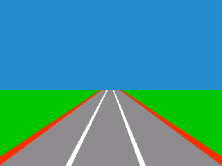
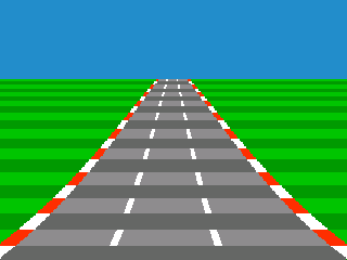
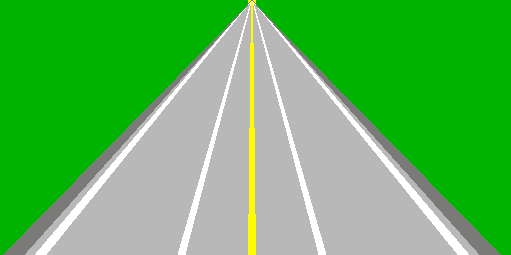
This image lacks road markings that create a good sense of perspective. For this effect, in games, in addition to other road markings, alternating dark and light stripes are used. To add them, let's define the “texture position” variable. This variable is zero at the bottom of the screen and increases its value with each line up. When its value is below a certain number, the road is drawn in one shade. When the value is above this number, it is drawn in a different shade. After the maximum value is exceeded, the position variable is again equal to zero, creating a repeating pattern.
However, changing it for each line is not enough, because then you will get only a few bands of different colors, which do not decrease with the removal of the road. So, we need another variable that will change by a specified amount. It needs to be added to another variable each line, and then add the last to the change in the position of the texture.
Here is an example of how the value of Z changes for each line when moving into the distance. After the variables, I wrote what I need to add to get the values for the next line. I called the values DDZ (delta-Z), DZ (delta-Z), and Z. DDZ remains constant, DZ varies linearly, and Z - along the curve. It is possible to consider the Z coordinate of the Z position, DZ the position velocity, and DDZ the position acceleration (change in acceleration). Note that the value "4" is chosen arbitrarily, because it is convenient for this example.
DDZ = 4 DZ = 0 Z = 0 : dz += 4, z += 4<br>
DDZ = 4 DZ = 4 Z = 4 : dz += 4, z += 8<br>
DDZ = 4 DZ = 8 Z = 12 : dz += 4, z += 12<br>
DDZ = 4 DZ = 12 Z = 24 : dz += 4, z += 16<br>
DDZ = 4 DZ = 16 Z = 40 : ..
Notice that DZ changes first, and then it is used to change Z. This can be explained as follows: let's say we are moving in texture at speed 4. This means that after the first line we read the texture in position 4. The next line will be in position 12. After it is 24. Thus, the passage through the texture is going faster and faster. That's why I call these variables the “texture position” (the place of the texture that we read), the “texture speed” (how fast we go through the texture) and the “texture acceleration” (how fast the texture speed changes).
We use a similar method for drawing curves and hills without too many calculations. Now, to create the illusion of texture movement, you just need to change the beginning of the texture position at the bottom of the screen for each frame.
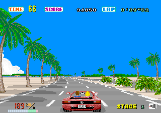
You may notice the disadvantage of this trick: the scaling factor is not accurate. This leads to a distortion, which I will call the "oatmeal effect." Such a deformation effect was present in early pseudo-three-dimensional games, for example, in OutRun: objects, including stripes on the road, seemed to slow down when moving from the center of the screen to the outside.
This method of finding the value of Z has another drawback: it is not easy to predict what the value will be at each distance, especially when using hills. We will learn a more complicated way, which I call the Z-map (Z-map). This is a table that calculates the distance Z for each raster line of the screen. But first, we need some more mathematics ...
Excursion into mathematics: a projection of a three-dimensional perspective
There are ways to get rid of the effect of oatmeal. However, their implementation requires knowledge of traditional three-dimensional mathematics. We need to find a way to translate the 3D coordinates so that they can be positioned on a 2D surface.
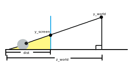
In the figure above, the eye (in the lower left corner) looks through the screen (blue vertical line) at an object in our three-dimensional world (“y_world”). The eye is at a distance of "dist" from the screen, and at a distance of "z_world" from the object. If you were engaged in geometry or trigonometry, you might have noticed that there are not two triangles in the picture. The first triangle is large, from the eye to the surface to the right and up to the object that the eye is looking at. I painted the second triangle yellow. It is formed by the eye, a point on the screen in which we see an object, and a surface.
The hypotenuses of these two triangles (the lines from the eye to the object) are at one angle, although one is longer than the other. In essence, it is the same triangle, only scaled down. This means that the ratio of horizontal and vertical sides will be the same! In a mathematical notation:
y_screen/dist = y_world/z_worldNow we need to convert the equation to get y_screen. We get:
y_screen = (y_world*dist)/z_world
That is, to find the y coordinate of the object on the screen, we take the y coordinate of the world, multiply it by the distance from the eye to the screen, and then divide by the distance in the world. Of course, if we do this, then the center of the look will be in the upper left corner of the screen! To verify this, it suffices to substitute y_world = 0. For centering, you need to add half the screen resolution to the result. The equation can be slightly simplified if we imagine that the nose is pressed against the screen. In this case, dist = 1. It turns out the following equation:y_screen = (y_world/z_world) + (y_resolution/2)
There is a relationship between the ratios and viewing angle, as well as image scaling, so that it does not depend on the screen resolution. But to solve the problem with the road, we will not need it. If you're interested, look at the diagram in top view: the angle to the edge of the screen is the scope, and the same connection is maintained.
More math: adding scope to a three-dimensional projection
In general, this is usually not necessary for most "road" engines. But this is useful so that the projection parameters do not depend on the resolution, or for objects that need to be rotated, or to integrate with genuine 3D effects.
Let's go back to the original projection formula. The “dist” value of the equations above will be called “scaling” here:y_screen = (y_world*scaling)/z_world + (y_resolution/2)
The idea is that we need to scale all the points on the screen by a certain amount, which will allow the points to remain visible within the field of view (field-of-view, FOV). For the x axis of the FOV and the y axis of the FOV, two constants will be needed.
For example, suppose we are working in a resolution of 640x480 and want the FOV to be 60 degrees. We saw the scheme of a three-dimensional projection in the side view. For this case, let's look at the diagram of the projected space in the top view: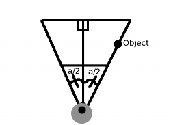
One way to solve the problem is to assume that if the object is on the right side of our FOV, it should be displayed on the screen at x = 640 (because the screen resolution is 640x480). If you look at the scheme, you can see that FOV can be divided into two right triangles, in which the angle of each is equal to fov_angle / 2 (a / 2). And since our FOV is a cone, the object located on the right edge of the FOV, i.e. x = R * sin (a / 2) and
z = R * cos (a / 2), where R is any radius value. We can, for example, take R = 1. And we need the object to be displayed on the screen at x_screen = 640. We get the following (taking into account the basic projection formula):x_screen=640 fov_angle=60 y_world=sin(60/2) z_world=(60/2) x_resolution/2=320 scaling=?
x_screen = (y_world*scaling)/z_world + (x_resolution/2)
640 = (sin(30)*scaling/cos(30)) + 320
320 = tan(30)*scaling
320/tan(30) = scaling
: scaling = (x_resolution/2) / tan(fov_angle/2)
We replaced a / 2 with 30 (half of 60 degrees), denoted as sin / cos = tan, and voila! You can check this by placing the object at the right end of the scope, substituting these values into the original projection equation and making sure that X takes the value 640. For example, the point (x, z) with coordinates (20, 34.64) will be at X = 640, because that 20 is 40 * sin (30), and 34.64 is 40 * cos (30).
It should be noted that the FOV values for the horizontal (x) and vertical (y) axes will be different for a standard and widescreen monitor in a horizontal position.
More accurate road: using the Z-card
To solve the perspective problem, we need to create a pre-computed list of distances for each line of the screen. In short, the problem is in describing the plane in 3D.
To understand how this works, imagine first a two-dimensional analog: the line! To describe the horizontal line in 2D, we can say that for each pair of coordinates (x, y) the y coordinate will be the same.
If we bring it into three-dimensional space, the line will become a plane: for each distance x and z, the coordinate y will remain the same! If we consider a flat horizontal surface, it does not matter how far the camera is located, y will be constant. It also does not matter how far the point is to the left or right, the value of y will always be the same.
Let us return to clarifying the distance to each of the lines of the screen: let's call our list a Z-card. The question of calculating the Z-map is to convert the three-dimensional projection formula to find the value of Z for each screen Y!
First, take the equation from the previous section:Y_screen = (Y_world / Z) + (y_resolution / 2)
Since we have Y_screen (each line), we transform the equation to find Z:Z = Y_world / (Y_screen - (height_screen / 2))
Y_world as a whole is the difference between the ground level and the height of the camera, which will be negative. It is the same for each line, because, as stated in the introductory paragraph, we are still interested in a flat road. Besides the fact that the road will look more clearly and avoid the “oatmeal effect”, there is another advantage: the simplicity of calculating the maximum rendering distance.
The road is located on the screen by reading this buffer: for each distance, you need to find out what part of the road texture belongs to it, noting how many units each line or pixel of the texture takes.
Although we know the distance for each row of the screen, it may be useful to cache for each row or the width of the road, or the scaling factor. The scaling factor is opposite to the distance chosen in such a way that the value on the line in which the graphic image of the player’s machine is the most is 1. It can be used to scale the sprites on a given line or to determine the width of the road.
Curves and turns
Create bends
To make the road curve, you just need to change the position of the center line in the shape of the curve. For this you can use a couple of ways. One way is the same way that the Z positions were created in the “Simplest Road” section: using three variables. That is, starting from the bottom of the screen, the amount by which the center of the road moves to the left or right of each line is steadily increasing. As with texture reading, we can consider these variables as the position of the center line (curve), the speed of the curve, and the acceleration of the curve.
However, this method has problems. One of them is that it is not very convenient to create S-shaped curves. Another limitation: the entrance to the turn looks exactly the same as the way out of it: the road is bent, and then just unbent.
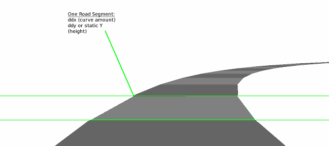
To improve the situation, you can introduce the concept of road segments. The road segment is a part invisible to the player. It can be considered an invisible horizontal separator, which sets the curvature of the road above this line. At any point in time, one of these segment dividers is at the bottom of the screen, and the other goes down at a constant rate to the very bottom. Let's call the lower segment the base segment, because it sets the initial curvature of the road. Here's how it works:
When we start to draw the road, we start by looking at the base point and, accordingly, set the drawing parameters. As the turn of his segment approaches, the line of the segment is at a distance and approaches the player almost like any other road object, except that it has to descend down the screen at a constant pace. That is, at a specific speed with which the player moves, the segment divider descends down the screen by the same number of lines per frame. Or, if a Z-map is used, for the same number of z-map elements per frame. If the segment “accelerated” towards the player, as they do 3d-objects on the track, the road would be bent too sharply.
Let's see how it works. Suppose the line segment for the left curve is down halfway down, and the base segment is just a straight road. When drawing the road, it will not start to bend until it collides with the “left curve” segment. Then the road curve begins to change with the pace indicated by this point. When the moving segment reaches the bottom of the screen, it becomes the new base segment, and the previous base segment rises to the top of the road.
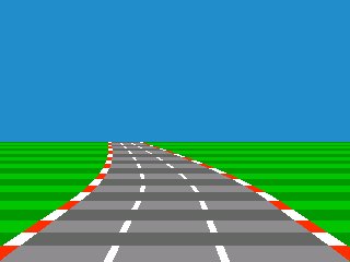
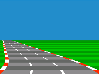
Two roads are shown below: one straight, followed by a left turn, and the other with a bend to the left, followed by a straight. In both these cases, the position of the segment is halfway down the Z-map (or halfway down the screen). In other words, the road starts to bend or become straight halfway down the road. In the first picture, the camera enters a turn, and in the second it goes out of it.
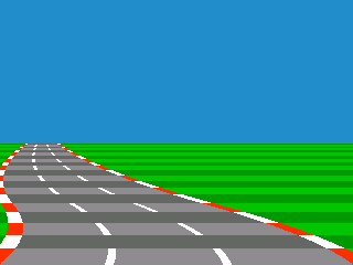
But the same technique and the same position of the segment, applied to the S-shaped curve:
The best way to track the position of a segment is to determine where it is on the Z map. That is, do not tie the position of the segment to the position Y on the screen, but tie it to the position on the Z-map. Thus, it will still begin on the horizon of the road, but it will be much more convenient to work with hills. It should be noted that on a flat road without changing heights, these two methods of tracking the position of a segment are similar.
Let's illustrate the above with the code:
current_x = 160 // 320 dx = 0 // , ddx = 0 // , , : Z- segment.position: dx = bottom_segment.dx Z - segment.position: dx = segment.dx "" ddx += dx current_x += ddx this_line.x = current_x "" // segment_y += constant * speed // , segment.position < 0 // 0 - bottom_segment = segment segment.position = zmap.length - 1 // segment.dx = GetNextDxFromTrack() // "" One of the great advantages of realizing curves in this way is that if there is a curve followed by a straight road, then the player will be able to see the straight road when exiting the curve. Similarly, if a curve is followed by a curve in a different direction (or even a more curved curve in the same direction), then the player can see this next section of the course before falling on it.
For the illusion to be complete, you need to add horizon graphics. With the approach of the curve the horizon does not change (or moves slightly). Then, when the curve is completely drawn, it is assumed that the machine turns along it, and the horizon quickly scrolls in the opposite direction of the curve. When the curve straightens again, the background continues to scroll until the curve ends. If you use segments, you can simply scroll (scroll) the horizon in accordance with the settings of the base segment.
The general formula for curves
Having studied the technique of curves, described in detail in the “Simplest Road” section, we can make an interesting conclusion. This conclusion is more relevant to mathematics than to the material presented above, and you can safely skip it if your graphics engine should not be resolution independent or use the “3d-projected segments” technique discussed in the section on hills.
Considering an example of a curve using “Z” from the “Simplest Road” section, you can see that the z-position (or x-position) of a given string is the sum of an increasing series of numbers (for example, 1 + 2 + 3 + 4). Such a series is called an arithmetic series or an arithmetic progression. If you use instead of 1 + 2 + 3 + 4, for example 2 + 4 + 6 + 8 or 2 * 1 + 2 * 2 + 2 * 3 + 2 * 4, you can get a sharper curve. “2” in this case is the variable segment.dx. It can also be factorized by getting 2 (1 + 2 + 3 + 4)! Now all you have to do is find a formula describing 1 + 2 + ... + N, where N is the number of lines that make up the curve. It is known that the sum of an arithmetic progression is equal to N (N + 1) / 2.Therefore, the formula can be written as s = A * [N (N + 1) / 2], where A is the sharpness of the curve, and s is the sum. This equation can still be converted to add a starting point, for example, the center of the road below the screen. If we denote it by “x”, then we get s = x + A * [N (N + 1) / 2].
Now we have a formula to describe the curve. We want to get an answer to the question “knowing the starting point x and N lines of the curve, what should A be, so that the curve reaches s at the end of the x-position?” Transforming the equation to find A, we get A = 2 (s - x) / [n (n + 1)]. This means that the sharpness of a given curve can be stored relative to the X position, which makes the graphics engine independent of resolution.
Turns in perspective style
It is much less interesting when, when turning in the game, only the sprite of the car moves. Therefore, instead of moving the sprite of the player’s car, we will leave it in the center of the screen and move the road, and more importantly, move the position of the center line in the front (i.e., lower) part of the screen. Now we assume that the player will always look at the road, so we will make the road end in the center of the screen. To do this, you will need a variable angle of the road. Therefore, we calculate the difference between the center of the screen and the position of the front of the road, and then we divide the road schedules into heights. This will give us the amount to move the center of the road on each line.
Sprites and data
Positioning objects and scaling
Sprites need to be drawn from behind in front. Sometimes this method is called the artist's algorithm . To do this, you must determine in advance where on the screen each object should be drawn, and then draw objects at different stages.
This is done in the following way: when we go over the Z-map while drawing the road, we also need to note which line of the screen each sprite should be associated with. If the sprites were sorted by Z, this is trivial: each time you read a new Z-map value, you need to check whether the Z position of the next sprite is closer to the camera than the current Z-map value, or if they are equal. If this is the case, then you should mark the sprite's Y screen position as belonging to the current line. Then check out the next sprite in the same way. Continue this process until we get a sprite from the list, whose Z position is further than the current one.
The position of the X object must be tracked relative to the center of the road. Then the simplest method of horizontal positioning of the sprite is to multiply the value by the scale factor of the current line (the reciprocal of Z) and add the result to the center of the road.
Storing route data
When I did my first demo with the road, I stored the level information in the list of events that should occur at certain distances. Of course, distances were indicated in units of the position of the texture. Events consisted of commands start and end curves. As I recall, the speed at which the road begins and ends to bend is arbitrary. The only rule is that it should correspond to the speed of the player’s car.
However, if you are using a system with segmentation, you can simply use a list of commands. The distance each team takes is similar to the speed at which the invisible segment moves to the bottom of the screen. It also allows you to create a route format that works for a tile map that allows you to transfer a fairly realistic track geography. That is, each tile can be one segment. A sharp turn can turn the track 90 degrees, and smoother - 45 degrees.
Road texturing
Now you may want to use on the road a real graphic texture instead of the changing lines that we have created at the moment. For this you can use a couple of ways. Cheap and easy way: prepare a couple of textures for the road (for the effect of changing lines). When drawing each horizontal line of the road, you need to stretch the texture to match the width of this line. Or, if stretching is not possible, you must select a string from one of two full bit images of the road (the approach used by the Outrunners).
If you want the road to look more accurate, make it so that Z for each line corresponds to the line number of the graphic texture. And voila! A single over-the-road road!
However, if you only need stripes of alternating colors, the answer is even simpler, especially when using a fixed point. For each Z you need to make one of the bits represent the shade of the road (dark or light). Then just draw the appropriate road drawing from the flowers for that bit.
The hills
Variations of the hills
It seems that there are an almost infinite number of ways to create the effects of the hills. Hill effects can be created with a wide range of geometric precision, with some less accurate techniques creating more convincing results. We will consider two possible ways.
Fake Hills
After a lot of experiments, I came to a flexible way to mimic the hills, which uses few calculations. In addition, it accurately tracks objects below the horizon. This is the effect of scaling and distortion, vertically stretching and compressing the road. To generate the curvature of the hill, it uses the same summation trick used to draw the curves.
Here's how to do it: first, the draw cycle should start from the beginning of the Z-card (nearest) and stop when it reaches the end (farthest). If we decrease the position of rendering each line by 1, the road will be drawn flat. However, if you reduce the position of rendering each line by 2, doubling the lines in the aisle, then the road will be drawn twice as high. And, finally, by varying the value of the decrement of the position of drawing each line, you can draw a hill, starting as a plane and rising up. If the next drawing position is farther from the current drawing position by more than one line, then the current Z-map line is repeated until we reach it, creating a scaling effect.
Descents from the hills are made in a similar way: if the position of the drawing increases, not decreases, then we will sink below the last drawn line. Of course, the lines below the horizon will not be visible on the screen. Only lines that are one or more pixels above the last row are drawn. However, we still need to track objects below the horizon. To do this, you need to take into account the position Y of each sprite when walking around the Z-map. Creating a Z-card, more than is necessary for a flat road, can help. Thus, when stretching the buffer, it will not become too pixelated.
Now we need to move the horizon so that the picture is convincing for the player. I love to use the background in the style of the game “Lotus”: in it the horizon not only consists of the outlines of the sky, but also of the graphics of a distant land. When the hill goes up (increasing the field of view), the horizon should descend slightly down from the top of the road. When the hill goes down and the camera "rests" on the hill (limiting the field of view), the horizon should rise up.
Here's what the effect looks like for descending from a hill and climbing onto it, of course, without horizon charts:
pros
- Low calculation load: no multiplication or division required
- Objects on the back of the hill are tracked.
- It seems that the viewing angle follows the player passing through the hills.
Minuses
- Accurate 3D geometry is not possible.
:
Such formulas of curves with accumulation can be used flexibly if you do not need insane curves or huge hills. In many games that use such tricks, the road scrolls so fast that even a small curve looks convincing.
However, to create a more impressive road you may need to exaggerate the effect. You can use high ddx or ddy in any of these curve formulas, but dx or dy should not exceed reasonable values. YouTube user Foppygames found another trick creating steeper curves from these formulas with accumulation: for each row, multiply the value of dx or dy by the value of z! This makes the curve more steep at a distance than it is in the foreground, and creates a rather convincing effect .
And the experiments don't end there. In fact, the best thing about these engines is that there are no “right” ways to implement them. Anything that creates nice looking curves and bends, is strongly encouraged! In my first road engine, I used a sine wave lookup table to bend the road.
You can also use multiplication: to shift the road to the right, you can, for example, multiply the x position by 1.01 for each row. To shift to the left by the same amount, multiply by 0.99 or 1 / 1.01 (the reciprocal of 1.01). However, armed with the knowledge that many old processors did not have multiplication operations or were weak in it, I stopped on the accumulation technique, because it only uses addition. It seemed to me a more "authentic" way to create the bends of the road.
In some games, for example, in OutRun, even the system of simple splines is used (at least judging by the excellent port on C ++ Cannonball made on the basis of reverse engineering .
So, playing and experimenting, you can choose the most suitable technique for you!
... or continue reading to find out the tricky trick mixing 3d-polygons. It is almost as fast, even more convincing and can be reproduced on the same old raster equipment. Intrigued?
Real 3d projected segments
Comparing 3d projected segments and raster roads
Raster roads are beautiful, but they can be made even more impressive by using a simple polygon rendering method. This rendering method can “pull” even the same weak raster equipment. However, it uses more computation.
This trick is known to be used in games like Road Rash and Test Drive II: The Duel. That's what it is: the track consists of polygonal segments. However, instead of moving in full 3d-space, they only move relative to the camera. For curves, the road still leans to the left or right, almost the same as on raster roads: there is no real rotation that would be present when turning on a curve in a fully polygonal engine.
Here is a brief explanation of the principle:
- Since the curves and angles of the roads are still simulated, costly rotation calculations will not be needed.
- In essence, the road is a strip of quadrangles: each section of the road is connected to the next section. This means that we can calculate the visibility of a part of the road only on the basis of its screen position Y relative to the previous neighbor.
- The relationship between these quadrilaterals never changes. That is, the angle never actually changes, so the quadrangles are always and automatically sorted by Z.
Simple 3d-road
First, we divide the road into polygonal quadrangles. Each of them will be called a segment. Like a segment in a fully raster road, here each segment still has a curve (ddx), and either a hill (ddy), or a position y, which determines its height. Of course, they may have other attributes, such as a change in surface graphics.
The figure below shows a segmented road made up of a small number of polygons. Therefore, we can easily see the boundaries between the segments and how they affect the curvature of the road:
When rendering, we first find the position of y on the screen of each 3d segment using the formula screen_y = world_y / z. Or if the division is too slow, then you can find the height above the ground of a given segment by multiplying the height of the segment by the scaling factor for this row. Then it can be subtracted from the reverse z-map (this map is the answer to the question: what will y be for each z position of the flat road?) To find the final position on the screen.
Then you need to linearly interpolate the width of the road and the texture (if required) between these heights. Understanding which 3d segments need to be drawn and which are not can be very simple: a three-dimensional segment will not be drawn from the front to the back of the screen, whose screen_y value is projected as less than the last three-dimensional segment drawn (however, its sprites can still be visible because they are issued - do not forget about it).
Scrolling road
Now we need to learn how to scroll through these segments, move the entire volume of polygons moving towards the camera. When the nearest polygon segment passes through the camera, you need to move all the way back to the starting point so that it closes. This is similar to how you can implement scrolling of a two-dimensional tile field by scrolling up one tile, and when it is reached, all tiles are shifted and new data of the tile map is loaded. Here we scroll up one segment, and when it is reached, we move the road back and load the new road data.
But there is another very important detail: for example, the road has a sharp curve. You may have noticed that when it bends around this polygonal curve, it fluctuates at the moment of crossing the border of the segments and the road is then cleared. This happens for an obvious reason: when passing through a curved segment, the center of the camera is associated with changes in the road. That is, by the time we reach the end of this segment, the road will no longer be centered. It looks as if we are driving at an angle. You may be tempted to correct this by moving the road to the center by simply interpolating the positions of x objects.
However this is not trueand does not solve the problem completely: if the road is curved in a straight line, everything will be fine. The problem is that the road is curving, so the polygons are not built at a distance! In other words, we approximate a curve using polygonal segments. We want the shape of the curve to be more or less constant, even when scrolling.
Jake on codeincomplete.com has a great solution to this problem. Instead of changing the position of the x road while moving along a segment, it is worth changing the initial dx value from 0 to something that keeps the road in the center when driving along the segment. To do this, use the following formula: The
dx = -percentage_of_segment_traversed * ddxpercentage of the segment can be in the range from 0 to 1.0 and returns to its original value when the camera crosses the segments.
From the point of view of mathematics, this makes X expensive as a function of its Z. In other words, we maintain the same curve shape, regardless of how the approximation points scroll. The frontmost segment is “dragged into place” with the rest of the road, and this means that the subsequent position of the X segments is placed correctly. You will notice this clearly if you test the way with a road of several polygons. This solves the following problems during the passage of the segment (assuming that the shape of the curve does not change):
- The center of the road (position x) remains constant
- The dx is adjusted so that the next segment starts at the correct x position regardless of the scrolling position of the road.
The video illustrates this technique. I used a small number of segments and a very sharp curve to demonstrate the method. Note that when moving polygons to the player, they create the perfect curve shape. This is more obvious if you follow the right side of the road.
Sprites placement
However, sprites on this three-dimensional segment should still be displayed and properly cropped - if you accept that you are doing your own renderer and do not use the Z-buffer. In fact, the sprites can be drawn at the last stage: if the sprite is on a fully visible segment, it does not need to be cut off, because it comes straight from the ground, which is our only polygon.
But if the sprite is on a segment that is invisible or partially visible, then we can easily cut it off. First find the top of the sprite. Then each line of the sprite will be drawn until it collides with the last visible screen position of the Y segment. That is, if there is a segment behind the sprite that should cover its part, then we stop rendering the sprite when we reach this line. And if the top of the sprite is below the Y position of the last segment, then the sprite will be completely invisible and can be skipped.
Variations and rendering technology
After we have introduced the term polygons, it may be tempting to believe that polygon rendering procedures are needed to work with them. Technologies such as OpenGL or a simple trapezoid rendering procedure will do just fine. But even tile and sprite two-dimensional equipment will be quite enough for this.
Notice that each beginning and each end of the road segment is completely horizontal. This means that they always begin and end on a single scan line. Almost the same way as a fully pseudo-three-dimensional road is rendered on tile equipment by scrolling flat road graphics, you can repeat this technique for three-dimensional segments. For more on this, see the section “Special Road Equipment”. Although it considers the equipment of arcade machines, originally intended for drawing the effects of the road, the same technique can be recreated in simple two-dimensional sprite systems using vertical scrolling of the road graphics along with the horizontal one.
Additional reading about three-dimensional projected segments
Since my demonstration of such a variation is not yet ready, I recommend studying the amazing Code inComplete manual if you are interested in the details of this technique.
pros
- For hills, you can use real three-dimensional geometry, which significantly increases the number of possible parts.
- A more holistic system: changes in the width of the earth and the road do not need to be performed in different techniques
Minuses
- Need more calculations
- You need to use a decent number of segments, otherwise the road will look like a deformed and polygonal one.
Accomplishment
Multiple roads
Most arcade racing games handle many roads at once. Although the most obvious reason for this is the presence of several roads on the screen at the same time, but in this way other effects can be achieved. For example, in OutRun, several roads are used to create a six-lane highway. This allows the game to easily expand and narrow the road, as well as create convenient ramifications. In this case, two roads are superimposed on each other, and one of them is given priority for drawing. Here is the famous beginning of the OutRun with and without two roads (look at the right side of the bushes):
And, more importantly, below is an example of a highway on which two roads are laid to create six lanes, with and without the second road:

Similar effects
Infinite “chessboard” The
infinite “chessboard” in the Space Harrier arcade game is a simple variation of the road creation technique. As in the case of roads, the game contains graphics of lines approaching the player in a perspective projection. In fact, Space Harrier uses the same equipment as the Hang-On.
The pictures below show the Space Harrier chessboard effect with palette changes and no changes. To turn it into a chessboard, you just need to change the color palette every few lines. This is similar to the light and dark stripes on the road.


What about scrolling left and right? This is just a variation of the turns in a perspective style: when a player moves to the left or right, the graphics of the earth are warped. After a few pixels slip, the earth "resets" or "collapses" its position. Therefore, it seems that it scrolls to the left or the right indefinitely.
Case study
Special equipment for roads
Despite the fact that there are many ways to render roads, it is interesting that many arcade games used equipment designed specifically for this purpose. These chips automate the principles of drawing roads, but not the road calculations themselves. A typical example is Sega's OutRun road chip used in games such as Super Hang-on, Outrun, and Space Harrier.
First, the chip had its own graphics memory. In this road ROM, a perspective view of the road was practically kept, flat, centered and without curvature. The programmer approximately indicated for each line of the screen that line of perspective graphics that needs to be drawn. Each line also had an X offset (for the curvature of the road) and each line had a different color palette (for drawing road markings and motion simulations). To demonstrate the example, here are some road graphics from the Sega racing game along with the road that was displayed in the game (special thanks to Charles MacDonald for his road viewing application):

The first thing you might notice is that the road graphics have a much higher resolution than the game graphics. In these examples, the road has a resolution of up to 512x256, and the resolution of the game display is only 320x224. This gives the graphics engine a sufficient amount of graphics to reduce the amount of distortion. You may also notice that the perspective of the road stored in the ROM is completely different from the perspective displayed in the game. This happened because the graphics in the ROM only stores how the road may look at different widths of the road. The choice of the necessary lines for each line of the screen from a large graphic image is the task of the program.
The equipment supports two roads at the same time, so you can assign priority to the left or right road. This is necessary for those parts of the game in which the road forks, or when the central divider is located between the lanes.
If you are hacking a ROM, you can study examples of “road” chips in the MAME files src / mame / video / segaic16.c and src / mame / video / taitoic.c. Note that the Sega road graphics is stored in a two-bit planar format, and the center of the graphics may have a fourth color (the yellow line shown in the figures above).
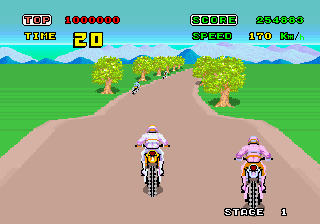
Enduro
Enduro is a great game. It was released in 1983 for an incredibly weak gaming console of the 70s. But she still manages to create a convincing effect of the road, complemented by changes in the weather and the alternation of day and night. In addition, this game is exciting even today!
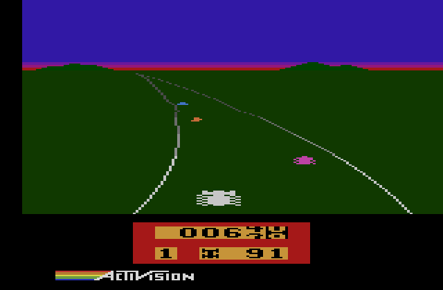
Enduro Screenshot
As we can see, Enduro is a little different from the road engines we reviewed. Immediately it becomes obvious that the road is drawn only by contours: the land on the sides of the road is not drawn in a different color. There are also no obstacles on the sides. If you play Enduro, you may notice that the road does not move in perspective. Instead, the sprite of the player’s cars and the road are shifted left and right, creating the illusion of turns.
To better understand why Enduro looks that way, let's look at the limitations of the Atari 2600. The Atari 2600 console was designed for Combat (tank game) and Pong games. Therefore, it could only display two sprites, two squares denoting the projectiles of each player, a square representing the ball, and a low-resolution background. And it's all.
But what is remarkable about Atari video equipment is that it is essentially one-dimensional: the program must update the graphics for each scan line itself. For example, to draw a sprite, the programmer needed to load a new line of graphics to display at the beginning of each development line. To draw a ball object, the programmer needed to turn on the ball when the TV beam was on the desired line, and turn off the ball when the beam approached a line on which the ball is no longer visible.
This led to an important side effect: a solid vertical line could be drawn down the screen, turning on the ball or projectile, and then not turning it off! If the programmer moved these objects on each line, then diagonal lines could be drawn.
Now back to our topic. You can draw a road using background blocks, but the resolution is too low to be effective. Therefore, in Atari racing games, two graphic objects of a projectile or ball were used to draw the left and right sides of the road, almost the same way they could be used to draw lines. Enduro, in particular, used the sprit of the projectile of the first player and the sprite of the ball to draw the left and right sides. In the Pole Position, both projectile sprites were used to draw the sides of the road, and then the ball sprite was used to draw the dotted line in the center.

Screenshots of the Pole Position at 2600 for comparison
We did not discuss how objects moved on the Atari 2600 line by line. The Atari graphics chip had a function called HMOVE (horizontal move, horizontal shift). He allowed the programmer to very easily set the offset of each line for all objects. The programmer needed only to indicate how many pixels different objects need to move, then call HMOVE, and voila - they all moved according to the desired values!
In Enduro, this function was used to draw curves. In short, Enduro created a table in memory of how the HMOVE values of the left and right sides change when the screen is drawn. It occupied almost half of the available memory of the Atari 2600. Since the memory of the Atari was so small, this value was read only for every four lines. For the left and right sides of the road two different tables were used.
When the road is straight, all the array values for the right side of the road were equal to 8. HMOVE uses only the top 4 bits, so the value 8 loaded in HMOVE did not move the sides of the road. The lower 4 bits were used as an approximate fixed-point form.
For example, here’s what a curve looks like in memory as it approaches (the horizon is the end of the array):
08,08,08,08,08,08,0a,0a,0b,0c,0e,0d,0e,0e,0f,10,13,11,12,13,14,17,16,17And the next frame:
08,08,09,09,0a,0a,0b,0b,0c,0d,0d,0e,0f,0f,10,11,12,12,13,14,15,16,17,18Notice that the increasing values of the curve gradually overwrite the smaller values, shifting to the front of the screen to create the illusion that the curve is approaching the player. And what does Enduro do with this data? Here is the part when used to record the curve for the right side of the road.
For each line of a road sweep:
LDA $be ; $be AND #$0f ; 4 ( HMOVE) ADC $e4,x ; (X - ) STA $be ; ( , ) STA HMBL ; Horizontal Motion - Ball ( ) What does this code do? So, $ be is a counter for an increasing curve value. When it loads, the upper 4 bits are discarded, leaving a range from 0 to 16 ($ 0-F). Then the curve table entry corresponding to this scan line is loaded and added. At the end, it is stored in the counter and loaded into the horizontal shift register for the ball object (right side of the road).
In this way we achieve several actions. First, the sides of the road move every two lines only when the road is straight: if the array consists only of the values 8 and $ be on the first line contains 0, then the next line will contain 8 (the upper nibble is still 0). The next line after it will contain $ 10. But when $ 10 is loaded again into register A on the next sweep line, the upper nibble is discarded, leaving 0 again! As a result, the counter alternately takes values of $ 10 and 8. Since HMOVE values use only the upper 4 bytes, the string is alternately shifted to 0 or 1 position.
Well, okay, what if the whole array consists of nines, and not eights? Here's what happens: the first line of the sweep 9 is saved to the ball's HMOVE register and written back to the counter. On the next line, 9 is again added to the value from the table, resulting in $ 12 (decimal 18). This will move the ball to 1 (the top 4 bits are 1). On the line after it, the upper nibble is discarded, leaving 2. Adding 9 from the table, we get $ B. Let's look at another scan line. The value B is loaded. There is no high nibble. Adding 9, we get $ 14 (20).
The sequence described above is 09,12,0b, 14. It will cause the ball to move every second line to these 4 lines. But gradually the lower nibble will be big enough for the procedure to shift the ball sprite two lines in the column to the left. The template will then collapse, but after a few more lines, the side of the road will again shift to two lines in the column. In essence, this is an example of simple and extremely fast fixed-point math.
There is another obstacle in the implementation of the road system on such weak equipment: the positioning of sprites. In more complex systems, sprites can be positioned horizontally on the road as a percentage of the road width. But this requires multiplication with a fixed or floating point, and these operations are performed very slowly in the processor 6502. For comparison, Enduro has only three possible positions for machines, which saves computational resources.
Road rash
Both Road Rash and Road Rash on 3do have awesome graphics engines. The original version of the game for Genesis provided a feeling of relatively accurate three-dimensionality on the Genesis 68000 processor with a frequency of 7.25 MHz, and also coped with scaling objects on the road in real time. The 3do version was no less surprising, because it turned out to be a mixture of 3D and pseudo-3D techniques. They were expertly combined, giving the player an amazing sense of speed.
As I mentioned above, the Road Rash and Road Rash engines for 3do were a mix of 3D tricks and pseudo-3D tricks. They used a technique similar to that described in the section “Real 3d-projected segments”: hills are in 3D space, and road curves are not. Road Rash curves use the same method described in this article, and each road segment has its own DDX or x-acceleration value. Each segment also has a height relative to the height of the last segment. There are 50 segments on the screen at the same time.
But Road Rash for 3do is really interesting because the programmers added a collapse that reinforces the sensation of speed: objects away from the camera move slower, and objects near the camera move faster.
Roadside Rash for 3do also added polygonal objects on the sidelines, whose X coordinates are still relative to the road. They are used to create hills, buildings, and other complex elements. It takes a large amount of data, so the geometry and textures are loaded from disk in the process of passing the road.
STUN Runner: The arcade machines against the Lynx
STUN Runner at the time of release on the arcade machines in 1989 was an amazing game. It used the technology of a fully three-dimensional polygons with a fill. She invited the player to take control of a futuristic racing machine, flying through the winding corridors at breakneck speed.
A little later, I saw a version for the Atari Lynx. The Atari Lynx was a portable system that was released around the same time as the original Game Boy. As in the Game Boy, it has an 8-bit processor at 4 MHz. So the port was terrible, right? Well, watch the video for yourself:
In fact, the port was fantastic! He became almost perfect and grabbed everything that made the game on arcade machines so amazing. And this is on the portable equipment era Game Boy. How did they do it?
It turned out that the Lynx had an important weapon in its arsenal: hardware scaling. But it didn’t help much when rendering polygonal graphics. It turns out that not only Lynx had aces up his sleeve: the author of the port also invented his own tricks.
To recreate the speed of the arcade machine Lynx-version STUN Runner returned to the pseudo-3D engine. The pieces of polygons that make up the walls are actually sprites. In essence, these are the objects on the side of the road that are glued to the road, almost the same as the objects on the side in any other pseudo three-dimensional racing game. They are drawn using the artist's algorithm (back to front). This creates a convincing illusion of polygonal graphics and allows you to take advantage of the strengths of the equipment. And to save space in the cartridge, one sprite did not make up the full ring of the tunnel graphics. This not only saves space on the absence of empty, transparent pixels, but also allows you to use the horizontal reflection function of graphics hardware.
Another interesting problem that the port author had to solve was the branching of the tunnel. It can be seen in the above video. The branching tunnel is in fact a large sprite, the scale of which increases when approaching the player. After the player chooses a new path, the fork pattern disappears. According to the author, sometimes you can see how the transport flies right through this sprite!
If you are interested in learning more about this, then read the interview with the original author at AtariAge .
Roads on Commodore 64
This information belongs to Simon Nicol , who has found a great technique for fast roads on the C64.
For a start, a small preface: on many console systems, pseudo-three-dimensional roads were created by drawing a straight road with tiles and line-by-line scrolling to create the appearance of a curvature. However, for a game with a normal level of frames per second, this method was too fast on the Commodore 64.
Simon's engine instead uses the C64 bitmap mode and the fast fill algorithm. Its fast fill algorithm uses self-modifying code to speed up rendering: each line is a sequence of pixel-by-pixel save operations that indicate the address in the video memory. However, at the moment when the color should change, the code changes. The save command is turned into a load command and the save address is turned into a new color number.
The main advantage of this technique is that it can still use the sprite combining technique, which allows you to display more than eight sprites on the screen. According to Simon: “To offset the horizontal scrolling, in order to get a stable raster effect, manipulations with the $ D011 register are necessary. Otherwise, the raster IRQ at $ D012 will flicker terribly depending on the number of sprites in a particular raster line. For a smooth display, it is necessary to ensure the necessary synchronism in the processor, or not to use on-screen graphics and simply change the border color. It will be solid and without flicker, but the road will not be displayed on the screen, because it will have to be turned off. Such smooth line-by-line color changes to the border were used to raster down the screen, and they can be used to pause there,where you need to display the top of the screen. This technique was called hold-off $ D011 or sometimes FLD (flexible line distancing) (it was used to get rid of bad lines on the Commodore VIC).
Other
Power Drift engines Power Drift is
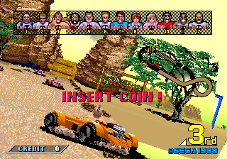
interesting because it is one of the few games I know of that used sprite-based 3D. Each fragment of the track is a small piece of the sprite, and the created Sega camera circling showed this. I have no evidence, but I think a similar system was used in games like the F1 Exhaust Heat and RadMobile. It is also worth noting that the Power Drift booth could tilt almost 45 degrees, so it was important to fasten it with a belt. Screenshots taken from system16.com.
Racin 'force
The reverse engineering of Racin 'Force was performed by Chalz Macdonald. Racin 'Force runs on a Konami GX PCB, which has a daughter board with voxel engine features. This hardware is based on old hardware that could only draw floor cards in the mode 7 style of the SNES console. Its capabilities have been expanded and allowed to create a height map using smart technology: it projects not only a tile map on a flat 3D surface, but also height information for each pixel onto its own separate 3D plane. Then, for each pixel of the screen, it searches for information about the heights on the projected height map and, if necessary, extrudes each pixel upwards. Screenshots taken from system16.com.
Further research
Here are interesting sites that may be useful for a deeper study of pseudo-three-dimensional roads:
Code
Formulas and tips
3D projection
y_screen = (y_world*scale / z) + (screen_height >> 1) or:
z = (y_world*scale) / (y_screen - (screen_height >> 1)) This formula takes the x or y world coordinates of the object, the z z of the object, and returns the x or y coordinate of the pixel. Or, with known world and screen coordinates, it returns the location by z.
The scale determines the field of view (field-of-view, FOV) and can be found as follows:
scale_x = x_resolution/tan(x_angle/2) scale_y = y_resolution/tan(y_angle/2) Fast linear interpolation
o(x) = y1 + ((d * (y2-y1)) >> 16) Here it is assumed that all numbers are represented as 16.16 with a fixed comma. y1 and y2 are two values between which interpolation needs to be performed, and d is a 16-bit fractional distance between two points. For example, if d = $ 7fff, then it will be the middle between two values. This is useful for determining where the value is between the two segments.
Fixed-point arithmetic
Floating-point operations are very costly on older systems that do not have specialized mathematical devices. Instead, a fixed-point system is used. In it, a certain number of bits are allocated to the fractional part of the number. For the test, let's assume that we allocated only one bit to the fractional part and left the remaining seven bits to the integer part. This bit of the fractional part will represent half (because half plus half is equal to the whole). To obtain the integer value of the number stored in this byte, the number is shifted one position to the right. This method can be extended and use any number of bits for the fractional and integer parts of a number.
Fixed-point multiplication is smarter than addition. In this operation, two numbers are multiplied, and then shifted to the right by the number of bits reserved for the fractional parts. Due to overflow, offset may sometimes be needed before multiplication, not after. See the fixed-point multiplication example in the “Fast Linear Interpolation” section.
Turning point
x' = x*cos(a) - y*sin(a) y' = x*sin(a) + y*cos(a) Here is a simple point rotation formula. In the article I briefly mentioned it as a very costly operation. As you can see, it uses at least two searches on the table, four multiplication operations, and two additions, but the sine and cosine values can be reused for each point. Rotation for hills means rotation along the Z and Y coordinates, rather than X and Y. For the derivation of this formula, see the section Turning axes .
Elimination of division
Instead of dividing the object into the z coordinate in standard projection formulas, you can use the properties of the road to speed up the calculations. Suppose we have the z and y position of a 3D segment, and we need to find which line of the screen it corresponds to. First, we read the z-card until we reach the z-position of the 3D segment. Then multiply the height of the segment by the corresponding scaling value. The result will be the number of pixels above the road to which the segment belongs.
Using Z as scaling value
Scaling procedures consist in increasing or decreasing the reading speed of the graphic data drawing procedure. For example, if you set a half-reading speed, the sprite will be twice the size. This happens because with each pixel rendering, the read position of the sprite data increases only by half, which leads to an increase in the read position by an integer number only for every two pixels.
Typically, the scaling procedure has parameters, such as x, y, and scaling factor. But since the coefficient is 1 / z, you can reuse the value Z of this sprite! However, we still need a scaling factor to determine the sprite's borders in order to center it when scaling.
Glossary
Bad string- in the C64 VIC II graphics chip on the first pixel of each background tile, the VIC replaces the processor to insert more data, such as colors. Because the program still has fewer cycles to calculate, this is called bad lines.
The elevation map is an array of elevation values. In a polygonal or voxel landscape engine, this can be a two-dimensional array (imagine the landscape in top view). However, in the road engine the height map is enough to be one-dimensional (imagine the landscape in the side view).
Indexed color mode- In older systems with a small number of colors on the screen, indexed color modes were usually used. One of the most popular indexed color modes is the 256-color VGA mode. In these modes, each pixel was represented by a byte. Each byte kept the index value from 0 to 255. When drawing the screen, the index number for each pixel was in the palette. Each entry in the palette could be one of 262,144 possible VGA colors. As a result, even though at the same time there could be only 256 colors on the screen, the user could choose each color from a much larger palette.
Linear interpolation is the process of obtaining intermediate values from a set of data by drawing lines between points.
Algorithm of the artist- is a way to draw overlapping objects from distant objects to the close ones. It ensures that closer objects will always be on top of distant ones.
Planar graphics mode is a mode in which an N-bit image was composed of N single-bit images combined to produce the final image. It is the opposite of most graphics modes (sometimes called chunky ), in which an N-bit image is composed of N-bit pixel values.
The raster effect is a graphical trick that uses the nature of most computer (raster) displays based on the scanning lines.
Scaling factor- the reciprocal of Z. The number by which to multiply the scale of the object at a given distance along the Z axis.
Segment (roads) - I use the term segment to indicate the position at which the road behaves in one way and above in another. For example, a segment may separate the left turn in the lower half of the screen from the right turn in the upper half. As the segment approaches the player, it seems that the road bends first to the left and then to the right.
Three-dimensional segment (roads)- I use this term to refer to a horizontal line having both a distance in Z, and a height in Y in world coordinates. Unlike the vertex, which can be a 3D point, the 3D segment will be a 3D line, whose left and right end points on the X axis are plus and minus infinity.
Voxel is a three-dimensional pixel. Voxel landscape engines and ray tracing engines became popular thanks to the game Commanche: Maximum Overkill.
Z-Map is a lookup table that links each line of the screen to a distance of Z.
Gallery
Below is a set of screenshots showing different ways to create custom road engines.
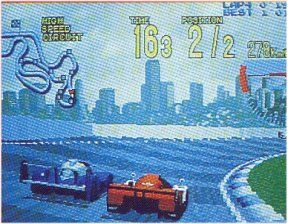
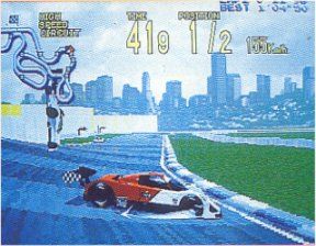
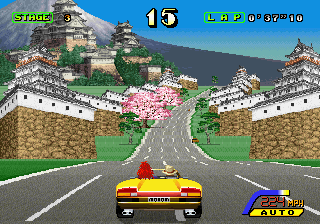
Cisco Heat
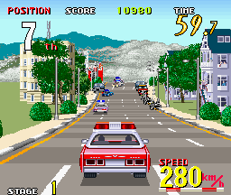
The hills in this game are approaching like a solid wall. Turns also look very exaggerated. The engine seems to be quite flexible and handles several roads at the same time, and can also show the height of one road relative to another.
Pole Position
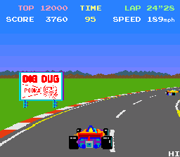
This is the first smooth motion pseudo three-dimensional game that I remember. Today it is not very impressive graphically.
Hydra
Another shoot em up for Atari in the style of Roadblasters. It has a very beautiful jump effect, in which the perspective of the road layer shifts, which is why the nearest objects disappear from the screen. In this game, objects are projected interestingly at different distances to the ground.
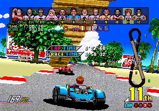
Outrunners
This sequel to Outrun is a great example of hills similar to roller coasters. Everything is quite exaggerated, resulting in a super-fast racing game, but with good handling.
Road rash
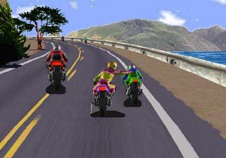
In the Road Rash version for the 32-bit generation of consoles, everything was textured, and the buildings were cleverly painted near the curb. Therefore, many people had the impression that this is a completely polygonal game that quickly works on 3do. However, the way objects are bent around the edges, the collapse of buildings and the fact that it was impossible to turn back, proves that this is not a completely polygonal game. The harsh lines on the pavement give a hint of a system of projected segments. Trails are very detailed and varied. The 16-bit Road Rash is also of high quality, it has a flexible engine with a small amount of fake texturing (but it was slow).
Turbo

Preceded by the Pole Position with hills and bridges. Are there any disadvantages? In the game there are no transitions from the hills to bridges and curves. For it used analog graphics scaling equipment.
Spy Hunter II
I do not know what the creators of Spy Hunter II thought. Good idea, bad performance. The effects of the road are very similar to the Turbo, but the transitions are made a little better.
Pitstop II

This technique is so fast that even on a weak Commodore 64 you could play a split screen racing game.
Enduro
Enduro demonstrates the use of pseudo-3D on the Atari 2600.
Enduro Racer
Not to be confused with Enduro: it was a 3D similar to Excitebike. The screenshot shows the hill making technique. The hills are quite sharp, flexible, but in general do not affect the position of the horizon, so I think that interpolated points were used.
Lotus
The Lotus used a technique of rather curved hills. Interestingly, Lotus painted the top of the road above the horizon, and then filled the gap with a solid color to simulate the descent from the hill.
Test Drive II
I don’t know exactly how Test Drive 2 graphics were created. Although it’s obvious that the race is not polygonal, it really tries to reproduce realistically a lot of roads. The game is similar to the Need for Speed series, but has overtaken it by several years in time of release.
Speed buggy
When cornering in this game, not only is the perspective shifted, but the road also slides a little to the left or right.
Source: https://habr.com/ru/post/325482/
All Articles