MIPSfpga and interrupts
The article provides several examples of how to configure and use MIPS32 Release 2 interrupts, including a detailed description of the configuration set in this case, and how to work with an external interrupt controller.
All the code described is published on github as part of the mipsfpga-plus [ L3 ] project.
Introduction
It is assumed that the reader:
- familiar with the subject area in the Harris-Harris volume [ L1 ];
- has some programming experience in microcontrollers (of any architecture), including the use of timers and interrupts;
- has access to the source codes MIPSfpga [ L2 ] and mipsfpga-plus [ L3 ];
By writing this article I do not set a goal to comprehensively present all the features of work with interruptions for the MIPS microAptiv cores, since this would require extensive translation of documentation and writing about the same amount of comments. The goal is to show working examples of configuration and use of interrupts in three possible modes: backward compatibility, vector, and using an external controller. Therefore, in order to make the reader feel more comfortable, it is recommended to get acquainted with the following sections of the documentation:
- MIPS32 MicroAptiv UP Processor Core Family Integrator's Guide [ D1 ]
(section 4 "Interrupt Interface"); - MIPS32 MicroAptiv UP Processor Core Family Software User Manual [ D2 ]
(sections: 5.1-5.6 "Exceptions and Interrupts in the microAptiv UP Core", 6.2.13 "Count Register", 6.2.15 "Compare Register", 6.2.16 "Status Register", 6.2.17 "IntCtl Register", 6.2 .22 "Cause Register", 6.2.28 "EBase Register", 6.2.33 "Config3 Register"); - Codescape GNU Tools for MIPS Programmer's Guide [ D3 ]
(sections: 15.5. "Exceptions", 15.6. "Interrupts").
In all examples, for clarity, the launch is described on the mipsfpga-plus system operating in the simulator. With equal success, this can also be done on hardware - the performance of the entire code has been tested on a Terasic DE10-Lite board [ L4 ].
Accepted notation
Signal names are in italics ( SI_Int [7: 0] ), unless otherwise indicated, all signals are interface signals for the top-level module of the MIPSfpga system (m14k_top). For registers, a saturated font ( Count ) is used, the names of individual bits (fields) are given through a dot indicating the registers to which they relate ( Cause.DC ), on separate extracts from the documentation the register fields can be indicated by subscripts ( Cause IV ). For all registers x32 width is assumed, if it is not specified separately. When specifying constants in the extracts from the documentation, there is an indication of the number system before the "lattice" symbol (16 # 180, 2 # 00001).
Since In MIPSfpga, unfortunately, the option "GPR Shadow Registers" (Shadow Register Set, SRS) is not available, then the article omits the details related to general purpose shadow registers. Where this functionality is found in the diagrams, it is reflected in a gray (faded) color.
Exception Handling
Exceptions are all events that lead to the transition of the processor in kernel mode: memory access errors, division by zero, etc., including interrupt requests from external devices. Handling all possible exceptions is an extensive topic that is not properly considered in isolation from the operating system (OS) kernel, which is clearly beyond the scope of this article. However, even if the use of the OS is not supposed (Bare Metal code), the developer should still provide for a minimal set of handlers in memory in order to learn about the occurrence of an exception and to prevent the program execution from going into “free float”.
if Status.EXL = 1 then vectorOffset ← 16#180 else if ExceptionType = TLBRefill then vectorOffset ← 16#000 elseif (ExceptionType = Interrupt) then // if (Cause.IV = 0) then vectorOffset ← 16#180 else if (Status.BEV = 1) or (IntCtl.VS = 0) then vectorOffset ← 16#200 else if Config3.VEIC = 1 then VecNum ← Cause.RIPL else VecNum ← VIntPriorityEncoder() endif vectorOffset ← 16#200 + (VecNum × (IntCtl.VS || 2#00000)) endif endif endif endif Cause.ExcCode ← ExceptionType // , Status.EXL ← 1 // , " " if Status.BEV = 1 then vectorBase ← 16#BFC00200 else // EBase[31:30] = 2'b10 // kseg0 kseg1 vectorBase ← EBase[31:12] || 16#000 endif // // vectorBase vectorOffset // 29 30 PC ← {vectorBase[31:30], (vectorBase[29:0] + vectorOffset[29:0])} The following algorithm is not taken into account in the above algorithm:
- exceptions that cause the processor to reset (Reset, SoftReset, NMI - cause a transition to 16 # BFC00000);
- EJTAG exceptions;
- Cache / SPRAM Parity error, which when Status.BEV = 0 instead of the cached kseg0 segment, is mapped to the non-cacheable kseg1 segment ( vectorBase [29] = 1'b1) and EBase [29:12] = 0 in this particular case means not 16 # 80000000 , and 16 # A0000000. In our case, this is not critical, since in the MIPSfpga project, the memory segments overlap (see the RTL code of the mfp_ahb_lite_decoder module) and the upper three bits of the address are ignored when accessing the memory;
- XTLB Refil exception with offset 0x80, which is not described in [ D2 ], but is mentioned in [ D3 ] and all supplied code examples. If someone from readers can clarify this point - I will be grateful for the information.
Full details of the exceptions can be found in [ D2 ].
Thus, even without using interrupts, the developer should ensure that exception handlers are available at the following offsets:
- 16 # 000 - TLB Refill Handler;
- 16 # 080 - XTLB Refil;
- 16 # 100 - Cache / SPRAM Parity error;
- 16 # 180 - General Exception Handler.
Interrupt Handling Modes
There are only three of them:
- Interrupt Compatibility mode - compatibility mode;
- Vector Interrupt (VI) mode - vector mode;
- External Interrupt Controller (EIC) mode - external interrupt controller mode.
By default, the processor starts in compatibility mode (Compatibility). Further, it can be changed by setting the corresponding values of bits (fields):
- Status.BEV - determines the base address from which the offset of the interrupt handler vector is calculated, is set programmatically, the value after reset is 1;
- Cause.IV - defines the offset of the interrupt handler vector, is set by software, the value after reset is not defined;
- IntCtl.VS - Vector Spacing, determines the offset between the vectors, is set programmatically, the value after reset is 0;
- Config3.VINT - Vectored interrupts, read-only, equal to 1 for all microAptiv cores, incl. and for MIPSfpga;
- Config3.VEIC - detects the presence of an external interrupt controller, is read-only, the value is set by the SI_EICPresent signal.
A full description of the listed bits (fields) and registers to which they relate is given in the documentation, we note the impact of the totality of their values on the interrupt handling mode:

System timer
Before proceeding to the description of work with interruptions consider one of their most frequent sources - the system timer. It is extremely simple in its capabilities, but it is part of the processor core and can work even in the power saving mode, which means it is available in any environment.
Two registers are used to work with it:
- Count - Counter register. If Cause.DC == 0 (disable count register, default = 0), is incremented by one for each processor tick. The only way to reset the counter values is to write a new value (for example, zero) to it, a timer interrupt signal (caused by the equality Count == Compare ) does not automatically reset the counter;
- Compare - The comparison register. When Count == Compare and Compare ! = 0, the SI_TimerInt signal, which serves as the source of the interrupt, is set to one, and the Cause.TI (timer interrupt) bit is simultaneously set. To reset this signal, you need to write to Compare .
To work with these registers, it is convenient to use the mips32_setcompare and mips32_setcount macros, which are declared in mips / cpu.h, to initialize and reset the timer, in fact, use the same code [ S0 ]:
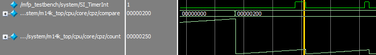
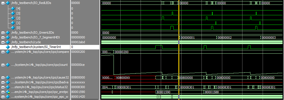
mips32_setcompare(MIPS_TIMER_PERIOD); //set compare (TOP) value to turn on /reset timer mips32_setcount(0); //reset counter The screenshot below shows the moments of timer initialization and reset when processing an interrupt.
The presence of the SI_TimerInt signal is not sufficient to trigger an interrupt. In order for it to be processed, it must be correctly routed at the RTL level, which depends on the current interrupt mode (Interrupt mode), which will be discussed below.
Interrupt Compatibility mode
Backward compatibility mode with MIPS32 Release 1. Key features:
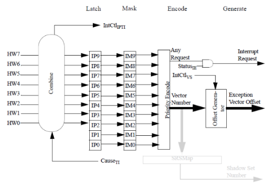
- 8 external interrupts are available: inputs SI_Int [7: 0] , which correspond to the flags Cause.IP9 - IP2 ;
- 2 software interrupts are available: Cause.IP1 - IP0 ;
- regardless of the input at which the interrupt occurred, control is transferred to a single handler, which, among other things, is responsible for handling exceptions;
- hardware interrupt prioritization is missing;
- the definition of the highest priority interrupt is left to the developer and is performed inside the handler by analyzing Cause.IP9 - IP0 , Cause.TI .
- the timer interrupt output ( SI_TimerInt ) must be associated with one of the SI_Int [7: 0] inputs. For this, it is not necessary to explicitly connect the signals to each other, you can use the input SI_IPTI [2: 0] , the value at which 0x2 means that SI_TimerInt is connected to SI_Int [0] , respectively, 0x7 will mean connection to SI_Int [5] . Connection to SI_Int [5] is considered traditional.
- if we talk about MIPS32 Release 1 processors, only 6 external interrupts were available in them ( Cause.IP9 - IP8 are missing) [ D4 ], hence the inability to switch the timer interrupt using SI_IPTI [2: 0] to any port more than SI_Int [5] . Thus, the backward compatibility mode provides several more options than was originally available in MIPS32 Release 1.
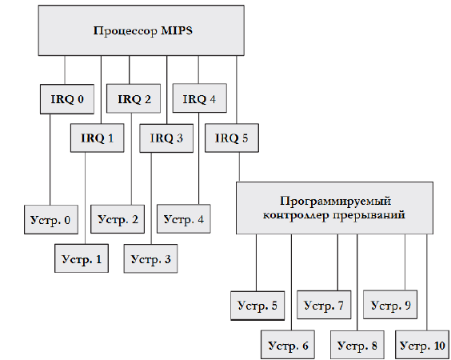
Those who received the first experience of development for embedded systems on relatively modern microcontrollers may experience some confusion from "only" 6 external interrupts and one common handler for everything, including the lion's share of exceptions. Here we should take into account some historicity of the MIPS architecture: it was assumed that the interrupt sources will be connected hierarchically, it was taken into account that the entry code in (exit) interrupt is common for all handlers, and since external devices are inherently slow (events rarely occur), then there is no particular loss in performance from "manual" checking of sources and priorities, and there is even some room for possible optimizations. An example of such a connection from [ L5 ] is shown below.
Even if these features are considered a “flaw”, they are easily compensated by the possibility of using an external interrupt controller connected via the corresponding interface of the MIPSfpga processor core, which will be discussed in the corresponding section.
Example
Start order
- Check that the following settings are set in the mfp_ahb_lite_matrix_config.vh file (the setting for using the external interrupt controller must be commited) [ S1 ]:
`define MFP_USE_WORD_MEMORY //`define MFP_USE_IRQ_EIC - Go to the directory mipsfpga-plus / programs / 06_timer_irq /;
- In the main.c file, install [ S2 ]:
#define RUNTYPE COMPATIBILITY - Run the build program and run it in the simulator:
02_compile_and_link.bat 05_generate_verilog_readmemh_file.bat 06_simulate_with_modelsim.bat - After the completion of the simulation script, press "no" to prevent the simulator from closing;
Program Description and System Configuration
The settings set in the RTL header files lead to the following configuration of the interrupt interface of the processor core [ S3 ]:
assign SI_Offset = 17'b0; //not used assign SI_EISS = 4'b0; //not used assign SI_Int[7:4] = 4'b0; assign SI_Int[3] = uart_interrupt; assign SI_Int[2:0] = 3'b0; assign SI_EICVector = 6'b0; //not used assign SI_EICPresent = 1'b0; //no external interrupt controller assign SI_IPTI = 3'h7; //enable MIPS timer interrupt on HW5The file exceptions.S contains the necessary interrupt vectors for operation, they are practically of the same type [ S4 ]:
.org 0x200 # set symbol offset from section beginning .weak __mips_isr_sw0 # if the symbol does not already exist, it will be created __isr_vec_sw0: la $k1, __mips_isr_sw0 # load interrupt handler (__mips_isr_sw0) addr beqz $k1, __general_exception # if it is not present then go to generic nop jr $k1 # jump to irq_sw0 nopException vectors differ from interrupt vectors in that if the corresponding handler is not defined in the program, the code is looped [ S5 ]:
.org 0x0 # set symbol offset from section beginning .weak _mips_tlb_refill # if the symbol does not already exist, it will be created __tlb_refill: la $k1, _mips_tlb_refill # load exception handler (_mips_tlb_refill) addr beqz $k1, __tlb_refill # if _mips_tlb_refill doen not exist then just loop here nop jr $k1 # jump to _mips_tlb_refill. # we can use 'j _mips_tlb_refill' nop # but it works only with 1st 28 bits of addrIn the mian.c file, the timer [ S0 ] is sequentially initialized:
mips32_setcompare(MIPS_TIMER_PERIOD); //set compare (TOP) value to turn timer on mips32_setcount(0); //reset counterInterrupt initialization [ S6 ]:
//compatibility mode, one common handler // Status.BEV 0 - place handlers in kseg0 (0x80000000) mips32_bicsr (SR_BEV); // Cause.IV, 0 - general exception handler (offset 0x180) mips32_biccr (CR_IV); // interrupt enable, HW5, SR_SINT1 - unmasked mips32_bissr (SR_IE | SR_HINT5 | SR_SINT1);And their processing in a single handler, assuming sequential: checking whether the exception is an interrupt, determining which interrupt is needed to be processed, and the processing itself [ S7 ]:
void __attribute__ ((interrupt, keep_interrupts_masked)) _mips_general_exception () { MFP_RED_LEDS = MFP_RED_LEDS | 0x1; uint32_t cause = mips32_getcr(); //check that this is interrupt exception if((cause & CR_XMASK) == 0) { //check for timer interrupt if(cause & CR_HINT5) { MFP_RED_LEDS = MFP_RED_LEDS | 0x10; n++; mipsTimerReset(); mips32_biscr(CR_SINT1); //request for software interrupt 1 MFP_RED_LEDS = MFP_RED_LEDS & ~0x10; } //check for software interrupt 1 else if (cause & CR_SINT1) { MFP_RED_LEDS = MFP_RED_LEDS | 0x8; mips32_biccr(CR_SINT1); //clear software interrupt 1 flag MFP_RED_LEDS = MFP_RED_LEDS & ~0x8; } } MFP_RED_LEDS = MFP_RED_LEDS & ~0x1; }- In this example, the associated interrupt flag (HW5) is used to check the interrupt of the system timer, for the same purpose you can use Cause.TI (macro CR_TI);
- Each of the stages of the program is reflected by the corresponding state of MFP_RED_LEDS;
In the timer interrupt (HW5), the counter is incremented, the timer is reset, and the program interrupt request flag SW1 is set [ S8 ]:
n++; mipsTimerReset(); mips32_biscr(CR_SINT1);In interrupt SW1, only the interrupt flag is reset [ S9 ]:
mips32_biccr(CR_SINT1);- All flag macros used for this are declared in mips / cpu.h;
In the code of the main function, the counter is cyclically outputted to 7-segment indicators [ S10 ]:
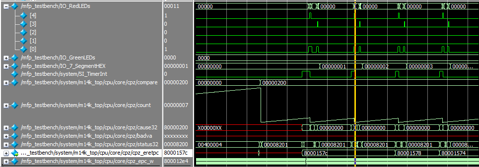
for (;;) MFP_7_SEGMENT_HEX = n;- The result of the program is a signal diagram similar to the one below. Please note that we can observe the values of the registers, in particular Cause and Status , PC , Count and ompare , in real time, which greatly simplifies debugging.
Vector Interrupt mode
Interrupt vector mode.
Key Features:
- the number and composition of interrupts processed (8 external and 2 software), as well as the procedure for working with SI_TimerInt are completely similar to Interrupt Compatibility mode;
- to handle each of the interrupts using its own handler (vector);
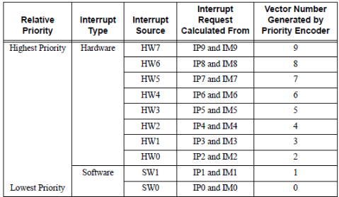
- interrupts have priorities that determine the order in which they are processed by the processor core. In order of increasing priority: SW0, SW1 (software interrupts), HW0-HW7 (hardware interrupts, correspond to SI_Int signals [7: 0])
- the first of the vector interrupt handlers is placed at offset 0x200;
- the offset between the first and second, as well as all subsequent processors is determined by the field IntCtl.VS . So for IntCtl.VS = 1, this offset will be 0x20:

Example
Start order
- It is completely analogous to that for backward compatibility mode, except for the need to install [ S2 ] in the main.c file:
#define RUNTYPE VECTOR Program Description and System Configuration
- RTL system configuration is similar to that for backward compatibility mode;
- It uses the same file exceptions.S [ S4 , S5 ] and absolutely identical timer initialization order [ S0 ];
Setting up interrupt operation is as follows [ S11 ]:
//vector mode, multiple handlers // Status.BEV 0 - place handlers in kseg0 (0x80000000) mips32_bicsr (SR_BEV); // Cause.IV, 1 - special int vector (offset 0x200), // where 0x200 - base for other vectors mips32_biscr (CR_IV); // get IntCtl reg value uint32_t intCtl = mips32_getintctl(); // set interrupt table vector spacing (0x20 in our case) // see exceptions.S for details mips32_setintctl(intCtl | INTCTL_VS_32); // interrupt enable, HW5 and SW0,SW1 - unmasked mips32_bissr (SR_IE | SR_HINT5 | SR_SINT0 | SR_SINT1);The program operation procedure is absolutely similar to the previously described one, except that the timer interrupt (HW5) is used to set not one but two program interrupt flags (SW0 and SW1), which will then be processed in order of priority [ S12 ]:
void __attribute__ ((interrupt, keep_interrupts_masked)) __mips_isr_hw5 () { MFP_RED_LEDS = MFP_RED_LEDS | 0x4; n++; mipsTimerReset(); mips32_biscr(CR_SINT0); //request for software interrupt 0 mips32_biscr(CR_SINT1); //request for software interrupt 1 MFP_RED_LEDS = MFP_RED_LEDS & ~0x4; }For interrupt handling SW0, a separate vector is used [ S13 ]:
void __attribute__ ((interrupt, keep_interrupts_masked)) __mips_isr_sw0 () { MFP_RED_LEDS = MFP_RED_LEDS | 0x2; mips32_biccr(CR_SINT0); //clear software interrupt 0 flag MFP_RED_LEDS = MFP_RED_LEDS & ~0x2; }- SW1 processing is performed by the same _mips_general_exception as in the case of backward compatibility mode, but with an important addition: the transition to this function is not because the processor immediately went to the offset 0x180. Execution is transmitted to 0x220, but since the mips_isr_sw1 function is not declared, then goes to general_exception (this is done by the assembler code from exceptions.S, which is given above) [ S14 ].
- The result of the program is a signal diagram similar to the following:
External Interrupt Controller mode
External Interrupt Controller
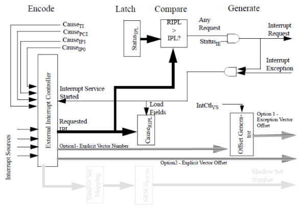
Before proceeding to the description of work in the External Interrupt Controller mode, consider how this module interacts with the processor core and what it is like.
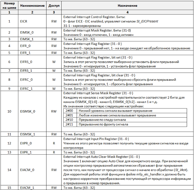
The controller's task is to register external interrupts and issue information on the most priority among them to the Interrupt Interface:
- SI_EICPresent - sign of the presence of an external interrupt controller;
- SI_Int [7: 0] - the priority of the requested interrupt;
- SI_EISS [3: 0] - determines the number of the set of shadow registers (shadow set number), in the case of MIPSfpga - not used;
- SI_EICVector - vector number of the requested interrupt;
- SI_Offset [17: 1] - offset of the requested interrupt;
Accepting the next interrupt request for processing, the processor informs the controller:
- SI_IAck a single impulse informs about the start of interrupt processing;
- SI_IPL [7: 0] - the priority of the processed interrupt;
- SI_IVN [5: 0] - the number of the vector of the interrupt being processed;
- SI_ION [17: 0] - offset of the interrupt being processed;
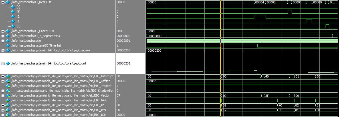
The typical interaction between the controller and the processor core is shown below:

You should also consider:
- Since In this case, interrupt prioritization is performed by a non-processor core, then all interrupts generated by it should also be sent to the controller input: a system timer interrupt ( SI_TimerInt signal Cause.TI flag), program interrupts ( SI_SWInt signals [1: 0] , Cause.IP1 flags - IP0 ) and others - is reflected in more detail in [ D2 ];
- How the kernel calculates the address of the handler offset: takes it directly from SI_Offset [17: 1] , or converts from SI_EICVector is determined by the currently activated option: "Option 1 - Explicit Vector Number" or "Option 2 - Explicit Vector Offset". In the first case - 64 vectors are available to us, in the second - we have 256K memory counted from the base to accommodate our vectors in it, which should be enough even for the most demanding task interruption. MIPS microAptiv core commercial customers set this parameter in the graphical configurator. It is not available in MIPSfpga, but this setting can be done in the file m14k_cpz_eicoffset_stub.v: 84. To do this, it is necessary to replace the value of eic_offset with one:
assign eic_offset = 1'b1; - The decision to process the interrupt requested by the controller is made by the processor on the basis of the minimum acceptable priority (set in Status.IPL ), all interrupts with a priority lower than the specified one will be ignored;
MIPSfpga-plus Interrupt Controller
Main characteristics:
- It is part of the MIPSfpga-plus [ L3 ] system;
- Up to 64 interrupts are available, the exact number of which can be specified in the configuration file (mfp_eic_core.vh) [ S15 ];
- Two types of input channels are implemented: direct (direct channel) and sensitivity setting (sense channel). For the first, an indication of the interrupt request is a high signal level. For the second, this parameter can be configured: front, decay, low signal level, any change in signal;
- The maximum number of channels such as sense channel is 32;
- The simplicity of the controller allows, if necessary, to implement even more interrupts, for this you will need to make small changes to the code, in particular, to add configuration registers;
- All signals input to the controller must be synchronized;
- The work is supported both in the mode "Option 1 - Explicit Vector Number" and "Option 2 - Explicit Vector Offset";
- The program can automatically configure the function of automatically lowering the interrupt flag at the beginning of its processing by the processor core;
- If necessary, a separate sandbox with a controller is available on github, in which its work was debugged [ L6 ];
- The controller is connected to the processor core at the top level of MIPSfpga-plus (mfp_system.v), EIC_input - signals from interrupt sources, other I / Os refer to the processor interrupt interface [ S21 ]:
`ifdef MFP_USE_IRQ_EIC .EIC_input ( EIC_input ), .EIC_Offset ( SI_Offset ), .EIC_ShadowSet ( SI_EISS ), .EIC_Interrupt ( SI_Int ), .EIC_Vector ( SI_EICVector ), .EIC_Present ( SI_EICPresent ), .EIC_IAck ( SI_IAck ), .EIC_IPL ( SI_IPL ), .EIC_IVN ( SI_IVN ), .EIC_ION ( SI_ION ), `endif //MFP_USE_IRQ_EIC The controller includes the following files:
- mfp_eic_core.v - controller core [ S17 ];
- mfp_eic_core.vh - main configuration file (see comments inside) [ S15 ];
- mfp_eic_handler.v - contains logic for converting the interrupt number to vector / offset and back (see comments inside) [ S18 ];
- mfp_eic_priority_encoder.v - priority encoder with a hierarchical (tree) organization [ S19 ];
- mfp_ahb_lite_eic.v is a top-level module that provides an interface with the AHB-Lite bus [ S20 ].
In order to form a general idea of the configuration of the controller, we list its configuration registers, their full description in [ D5 ]. For all registers except EICR , EISMSK_0 and EISMSK_1, it is assumed that the bit number corresponds to the controller's input number. So, for example, EIFR_0 [3] = 1 - means that an unhandled interrupt is waiting for input 3.
Example
Start order
- Check that the following mode [ S1 ] is set in the file mfp_ahb_lite_matrix_config.vh:
`define MFP_USE_IRQ_EIC `define MFP_USE_WORD_MEMORY - Check that the m14k_cpz_eicoffset_stub.v file is set to:
assign eic_offset = 1'b0; - Go to the directory mipsfpga-plus / programs / 07_eic /;
- Run the build program and run it in the simulator:
02_compile_and_link.bat 05_generate_verilog_readmemh_file.bat 06_simulate_with_modelsim.bat - After the completion of the simulation script, press "no" to prevent the simulator from closing;
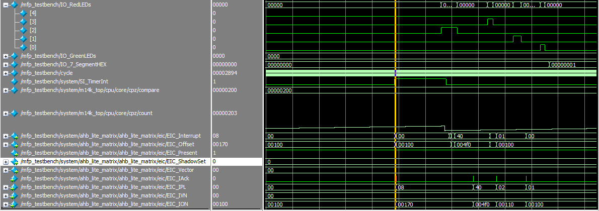
Program Description and System Configuration
The settings set in the RTL header files lead to the following configuration [ S16 ]:
wire [ `EIC_CHANNELS - 1 : 0 ] EIC_input; assign EIC_input[`EIC_CHANNELS - 1:8] = {`EIC_CHANNELS - 6 {1'b0}}; assign EIC_input[7] = SI_TimerInt; assign EIC_input[6] = 1'b0; assign EIC_input[5] = uart_interrupt; assign EIC_input[4:2] = 3'b0; assign EIC_input[1] = SI_SWInt[1]; assign EIC_input[0] = SI_SWInt[0]; assign SI_IPTI = 3'h0;- Interrupt Interface bus signals are processed by the mfp_ahb_lite_eic module, as shown above;
The file exceptions.S is similar to the two previous examples, except for the naming of interrupts and their number. So, the latest HW63 is located at offset 0x9E0 [ S22 ]:
.org 0x9E0 .weak __mips_isr_eic63 __isr_vec_eic63: la $k1, __mips_isr_eic63 beqz $k1, __general_exception nop jr $k1 nop- All macros necessary for working with the registers of the controller are moved to the file eic.h [ S23 ];
- The timer is initialized in main.c in the same way as before;
Initialization of interrupts [ S24 ]:
//eic mode //unmask interrupt MFP_EIC_EIMSK_0 = (1 << IRQSW0) | (1 << IRQSW1) | (1 << IRQTIMER); MFP_EIC_EIMSK_1 = (1 << IRQ63); //enable auto clear MFP_EIC_EIACM_0 = (1 << IRQSW0) | (1 << IRQSW1) | (1 << IRQTIMER); //set interrupt on rising edge of the signal MFP_EIC_EISMSK_0 = (SMSK_RIZE << SMSKSW0) | (SMSK_RIZE << SMSKSW1) | (SMSK_RIZE << SMSKTIMER); // Status.BEV 0 - vector interrupt mode mips32_bicsr (SR_BEV); // Cause.IV, 1 - special int vector (0x200) // where 0x200 - base when Status.BEV = 0; mips32_biscr (CR_IV); // get IntCtl reg value uint32_t intCtl = mips32_getintctl(); // set interrupt table vector spacing (0x20 in our case) // see exceptions.S for details mips32_setintctl(intCtl | INTCTL_VS_32); // enable external interrupt controller // enable interrupts MFP_EIC_EICR = 0x1; mips32_bissr (SR_IE);- RTL : interrupt_sence — [ S28 ], interrupt_channel — EIFR [ S29 ]. priority_encoder — EIC_input , [ S19 ]. handler_params_encoder [ S18 ], /;
, (Option 2 — Explicit Vector Offset), (m14k_cpz_eicoffset_stub.v), mfp_eic_core.vh [ S15 ]
`define EIC_USE_EXPLICIT_VECTOR_OFFSET- / , .. , mfp_eic_handler.v IntCtl.VS = 1 (32 ) [ S25 ];
, [ S26 ]:
ISR(IH_SW0) { MFP_RED_LEDS = MFP_RED_LEDS | 0x1; mips32_biccr(CR_SINT0); //clear software interrupt 0 flag MFP_RED_LEDS = MFP_RED_LEDS & ~0x1; }- ISR EH_GENERAL eic.h [ S27 ];
- :
- :
void __attribute__ ((interrupt)) v0 (); void __attribute__ ((interrupt, use_shadow_register_set)) v1 (); void __attribute__ ((interrupt, keep_interrupts_masked)) v2 (); void __attribute__ ((interrupt, use_debug_exception_return)) v3 (); void __attribute__ ((interrupt, use_shadow_register_set, keep_interrupts_masked)) v4 (); void __attribute__ ((interrupt, use_shadow_register_set, use_debug_exception_return)) v5 (); void __attribute__ ((interrupt, keep_interrupts_masked, use_debug_exception_return)) v6 (); void __attribute__ ((interrupt, use_shadow_register_set, keep_interrupts_masked, use_debug_exception_return)) v7 (); void __attribute__ ((interrupt("eic"))) v8 (); void __attribute__ ((interrupt("vector=hw3"))) v9 (); :
- use_shadow_register_set , .. MIPSfpga;
- interrupt("vector=hw3") ;
- , (interrupt, keep_interrupts_masked), :
void __attribute__ ((interrupt, keep_interrupts_masked)) __mips_isr_sw0 () { 80001544: 401b7000 mfc0 k1,c0_epc 80001548: 27bdfff0 addiu sp,sp,-16 8000154c: afbb000c sw k1,12(sp) 80001550: 401b6000 mfc0 k1,c0_status 80001554: afbb0008 sw k1,8(sp) // k1 status.exl,.erl,.um, .ie; 80001558: 7c1b2004 ins k1,zero,0x0,0x5 // status 8000155c: 409b6000 mtc0 k1,c0_status 80001560: afbe0004 sw s8,4(sp) 80001564: 03a0f025 move s8,sp ... } 80001568: 03c0e825 move sp,s8 8000156c: 8fbe0004 lw s8,4(sp) 80001570: 8fbb000c lw k1,12(sp) 80001574: 409b7000 mtc0 k1,c0_epc 80001578: 8fbb0008 lw k1,8(sp) 8000157c: 27bd0010 addiu sp,sp,16 80001580: 409b6000 mtc0 k1,c0_status 80001584: 42000018 eret - , (interrupt), :
void __attribute__ ((interrupt)) __mips_isr_hw5 () { 80001588: 401a6800 mfc0 k0,c0_cause 8000158c: 401b7000 mfc0 k1,c0_epc 80001590: 27bdfff0 addiu sp,sp,-16 80001594: afbb000c sw k1,12(sp) 80001598: 401b6000 mfc0 k1,c0_status // k0 cause.ip7-ip2 8000159c: 001ad282 srl k0,k0,0xa 800015a0: afbb0008 sw k1,8(sp) // k1 cause.ip6-ip2 status.im7-im2 800015a4: 7f5b7a84 ins k1,k0,0xa,0x6 // k1 status.exl,.erl,.um; // .ie ( 1) 800015a8: 7c1b2044 ins k1,zero,0x1,0x4 // status 800015ac: 409b6000 mtc0 k1,c0_status 800015b0: afbe0004 sw s8,4(sp) 800015b4: 03a0f025 move s8,sp ... } 800015b8: 03c0e825 move sp,s8 800015bc: 8fbe0004 lw s8,4(sp) //disable interrupts (status.ie = 0) 800015c0: 41606000 di 800015c4: 000000c0 ehb 800015c8: 8fbb000c lw k1,12(sp) // epc 800015cc: 409b7000 mtc0 k1,c0_epc 800015d0: 8fbb0008 lw k1,8(sp) 800015d4: 27bd0010 addiu sp,sp,16 // status 800015d8: 409b6000 mtc0 k1,c0_status 800015dc: 42000018 eret - , keep_interrupts_masked, , . .
Thanks
The author is grateful to the team of translators of the textbook by David Harris and Sarah Harris “Digital Circuit Design and Computer Architecture”, by Imagination Technologies for the academic license for a modern processor core and personally for Yuri Panchul YuriPanchul for his work on promoting MIPSfpga.
Links
[L1] - Digital circuit design and computer architecture ;
[L2] - How to start working with MIPSfpga ;
[L3] - MIPSfpga-plus project on github ;
[L4] — FPGA Terasic DE10-Lite ;
[L5] — Embedded Linux System Design and Development P. Raghavan, Amol Lad, Sriram Neelakandan ( );
[L6] — ahb_lite_eic github ;
[L7] — Codescape MIPS SDK ;
Documentation
[D1] — MIPS32 microAptiv UP Processor Core Family Integrator's Guide ;
[D2] — MIPS32 microAptiv UP Processor Core Family Software User's Manual ;
[D3] — Codescape GNU Tools for MIPS Programmer's Guide ;
[D4] — MIPS32 Architecture For Programmers Volume III: The MIPS32 Privileged Resource Architecture ;
[D5] — MIPSfpga+ External Interrupt Controller ;
[D6] — MIPS32 microAptiv UP Processor Core Family Datasheet ;
Images and tables
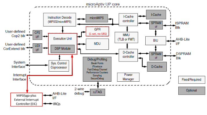
[P0] — MIPS 32 microAptiv UP Core Block Diagram (: D6 );
[P1] — ;
[P2] — MIPS. ();
[P3] — (: L5 );
[P4] — . ();
[P5] — (: D2 );
[P6] — (: D2 );
[P7] — (: D2 );
[P8] — . ();
[P9] — (: D2 );
[P10] — (: D1 );
[P11] — (: L6 );
[P12] — , ();
[P13] — , ().
References to source code
[S0] — ;
[S1] — mipsfpga-plus ;
[S2] — 06_timer_irq ;
[S3] — mipsfpga-plus ;
[S4] — ;
[S5] — ;
[S6] — ;
[S7] — ;
[S8] — ;
[S9] — ;
[S10] — main 06_timer_irq ;
[S11] — ;
[S12] — ;
[S13] — ;
[S14] — ;
[S15] — mipsfpga-plus ;
[S16] — mipsfpga-plus ;
[S17] — ;
[S18] — ;
[S19] — ;
[S20] — AHB-Lite ;
[S21] — ;
[S22] — HW63 ;
[S23] — ;
[S24] — ;
[S25] — Setting the vector offset increment in the external interrupt controller mode ;
[S26] - Interrupt handler in the external interrupt controller mode ;
[S27] - ISR and EH_GENERAL macros ;
[S28] - Module interrupt_sence ;
[S29] - Module interrupt_channel .
')
Source: https://habr.com/ru/post/324900/
All Articles