Guess the filter by impulse response

On some site, in some forum, a good young man nicknamed SciFi puzzled his team with history.
He found in the technical guidance materials of a foreign company Texas Instruments [FSK Modulation and Demodulation With the MSP430 Microcontroller] the digital filter he needed. But foreigners were very cunning, and in the source code they gave the following:
************************************************** * Running this filter takes 113 cycles ************************************************** ;***************************************************** ; New simpler filter at following specification ; Freq_Stop: 2.5KHz, Attenuation_Stop: 40dB ; Freq_Pass: 1.4KHz, Attenuation_Pass: 1dB ; Order of filter = 5 ;***************************************************** filters: bis #INTERRUPT_TOGGLE,global_status mov #WDF_PARMS,mem_ptr .word 4f16h .word 0000h .word 498fh .word 0000h .word 4f17h .word 0008h .word 8607h .word 4708h .word 1108h .word 4806h .word 1108h .word 1108h .word 1108h .word 1108h .word 1108h . . . Encrypted the demons! But the good fellow of SciFi, also did not miss. Overpowered their tricks and translated their secret writing into C:
')
signed short filter(signed short x) { static signed short fltmem[5]; signed short r6, r7, r9; r7 = fltmem[4] - fltmem[0]; fltmem[0] = x; r6 = (r7 >> 1) - (r7 >> 6) - fltmem[4]; fltmem[4] = fltmem[3]; fltmem[3] = r6; r6 -= r7; r7 = fltmem[2] - x; r9 = (r7 >> 3) - (r7 >> 6) + fltmem[2]; r7 -= r9; fltmem[2] = fltmem[1]; fltmem[1] = r7; return (r6 - r9)>>1; } As it turned out, the demons were encrypted twice. This code was obtained explicitly using a compiler, so only the compiler can use relative addressing. But the code itself deserves interest and respect. As you can see, it does not contain multiplication operations and can be effectively executed even on the simplest processors. The good fellow SciFi, and all the others, had a question: “What kind of filter is it?”.
To restore the block diagram of the filter on such a code, if possible, it is very time consuming. Therefore, we will go the other way. The conclusion about the type and parameters of the filter will be done on the amplitude-frequency characteristic (AFC). How to get it? Yes, how to send two bytes.
Immediately, we note that this filter is a filter with an infinite impulse response. This is guessed in the source code, the state of the filter is stored in the static array signed short fltmem [5];
We remove 60 samples of the filter impulse response, that is, the filter response to a single impulse. But in the conditions of integer arithmetic, in order to get the final result with the best accuracy, we will input not 1 but 10000 values to the filter input. More precisely, the maximum possible number that does not cause overflow must be supplied.
Test code for removing impulse response:
printf("%d\r\n", filter(10000)); for(int i=1;i<100;i++) { printf("%d\r\n", filter(0)); } The result obtained, using copy-pasting, will be processed in the mathematical package MathCad.
Construct a graph of impulse response. On the interval of 0-20 counts, it looks like this:

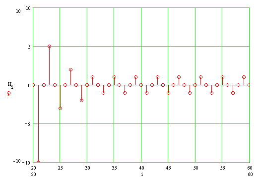
And on the interval of 20-60 samples, it looks like this:

From the analysis of the impulse response it is clear that the filter is not without flaws. The impulse response contains continuous oscillations of amplitude one discrete. In the theory of the synthesis of filters with an infinite characteristic [Goldenberg LM and others. Digital signal processing. M .: Radio and Communications, 1985] it is accepted to call such oscillations limit cycles, which arise due to the rounding error of integers.
The complex transfer coefficient of the filter under study can be defined as the Fourier transform of the impulse response. Only in the case of a discrete impulse response, integration over the time axis can be replaced by addition over all nonzero samples. In our case, the complex ratio of the transmission case is determined by the expression:

Where H is an array of impulse response samples;
f is the frequency normalized to the sampling rate;
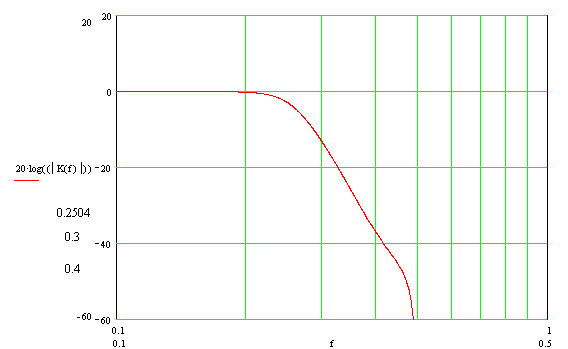
We construct a graph of the modulus of the complex transmission coefficient, amplitude-frequency characteristic, in a logarithmic scale (LAFC). Here and below, when plotting graphs, the frequency normalized to the sampling frequency is used.

Using the built-in tools of the mathematical package, we define the key points of the frequency response:
- Filter cut-off frequency by -3dB level - 0.25
- The transmission coefficient at a frequency of 0.3 - -13.266dB
- The transmission coefficient at a frequency of 0.4 - -37.013dB
Accordingly, the slope of the characteristic outside the passband is:
 DB / decade
For completeness, we give the phase-frequency characteristic (phase response):

The phase shift at a frequency of 0.48 is (180 + 180 + 87) = 447 degrees. Breaking a phase on a graph can be puzzling if you forget about the ambiguity of the arctangent.
Also, for the sake of completeness, we give the group delay time (GDT).

Now, deep in thought, you can answer the question “What is this filter?” .
The order of the filter. From the analysis of the logarithmic amplitude-frequency characteristic, it can be assumed that this filter is a 10 order link, the characteristic slope outside the passband is about 20 * 10 = 200 dB / decade. But from the analysis of the phase characteristics it can be seen that the phase shift tends to 90 * 5 = 450 degrees. Here, the inexperienced “filter guesser” involuntarily has thoughts about the non-minimal phase property of this link. But do not forget that the “analog” frequency is displayed in the “digital” through the tangent and, therefore, the laws of the analog world (20 dB / decade, etc.) work only at frequencies much less than the sampling frequency. In our case, we consider LAFH in the area close to half the sampling rate, and the laws of the analog world do not work.
Thus, by the form of the phase characteristic, it can be concluded that this link is a link of 5th order.
Type of filter. Taking into account the form of LAFC (in the bandwidth of LAFC is as flat as possible) and the type of graph of the HRT (extremum near the cut-off frequency), it can be assumed that this link is a Butterworth filter. To confirm our assumption, we construct LAFC, PFH and GHZ of an ideal digital Butterworth filter with a cut-off frequency of 0.25 synthesized by the bilinear transformation method [ Wikipedia ].
On the graphs, a red solid line indicates the values corresponding to the filter under investigation, a blue dashed line - an ideal digital Butterworth filter synthesized by the bilinear transformation method


As can be seen from the graphs, the almost complete coincidence of the parameters of the studied filter with the parameters of an ideal digital Butterworth filter synthesized by the bilinear transformation method.
Conclusion
In this paper, we investigated the remarkable implementation of the 5-order Butterworth digital filter. This implementation of the filter, despite its shortcomings in the form of a limit cycle, deserves great respect. Texas Instruments engineers managed to implement a fairly complex filter algorithm of 5 order in integers, not using the multiplication and division operations, while ensuring acceptable stability and consistency of the filter characteristics to the prototype.
Your humble servant sincerely hopes that the method used to analyze the code of digital filters used in this work will be interesting and useful to the reader.
Source: https://habr.com/ru/post/324522/
All Articles