Parametric modeling in CAD SolveSpace: Introduction
Many of us at school or university attended drawing lessons, but not many of us liked it. I spent hours with the ruler, compass and a poorly sharpened pencil, trying to draw dimension lines, endless hatching and strange shapes evenly and without blots, to some might seem interesting. Moreover, by that time there already existed computer programs capable of automating this boring, senseless, and ruthless occupation. A real breakthrough in the field of design of parts and preparation of design documentation occurred in 1989 with the debut of parametric modeling in the Computer-Aided Design (CAD) System Pro / Engineer.
This is the introductory article for the Parametric Modeling series. From this cycle you will learn about the internal structure of the real solver of geometric constraints , problems and their solutions on the example of open-source CAD "SolveSpace" . To whom the world of three-dimensional modeling is not alien, welcome under kat!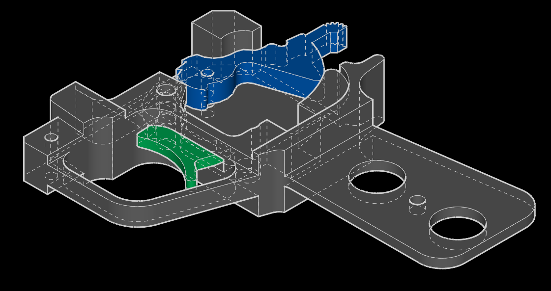
Model trigger RPG-7, created in CAD SolveSpace
Idea
Parametric modeling is based on a simple idea: to express complex geometric shapes of products using simple primitives (entities) , the shape of which is set using parameters (parameters) and the relations between them. Parameters can be the coordinates of points, angles, lengths, radii of circles or ellipses. Relations between parameters are called constraints . For a design engineer, such restrictions appear as dimensions or geometrical relations of incidence (coincidence), parallelism, perpendicularity or tangentity of the simplest geometric forms: points, lines, circles, ellipses, etc. The set of primitives that serve as the basis for constructing a geometric representation of a part, called a sketch . With this approach, the process of building a sketch is reduced to the formation of a rough outline of the contour of objects and the imposition of such restrictions that uniquely determine the values of the parameters of all primitives. The advantage of this approach is that the engineer does not need to accurately determine the coordinates of all objects, it is enough to specify only the geometric relationships between objects, and all the work on calculating the resulting coordinates of objects is performed by the geometric constraint solver - the basis of the parametric modeling approach. It is the presence of such a solver that distinguishes parametric CAD systems from the rest.
SolveSpace
Details of the implementation of the parametric modeling system will be considered on the basis of the open-source project SolveSpace created by Jonathan Westhues and currently supported by the open-source community of developers, including the author of this article, that is, me .
Among all open source projects, SolveSpace has the most adequate implementation of a geometric constraint solver . SolveSpace solver has a si-like interface and is available for licensing and use in commercial projects. The main advantage of the solver created by Jonathan is the symbolic approach to writing the original equations, which makes it very quick and easy to create new constraints, and also provides the ability to calculate expressions in the value fields. Another advantage of SolveSpace solver is the ability to consistently solve both two-dimensional and three-dimensional constraints.
As a counter-example, we can give the built-in FreeCAD solver, which is built on other principles, which causes a number of problems. One of the problems is the difficulty of adding new constraints due to the fact that you have to manually write down all the partial derivatives of the equations. But the main disadvantage of the FreeCAD solver is its limited scope in the design of two-dimensional sketches, which negatively affected the functionality of FreeCAD - it still does not have the normal ability to make three-dimensional assembly of parts.
Sketch
Despite the fact that SolveSpace is a parametric system of three-dimensional modeling, three-dimensional bodies are created based on a set of two-dimensional contours. Contours in SolveSpace can consist of line segments, circles and their arcs, as well as cubic splines. Hierarchically nested contours become “holes”, and contours nested in “holes” again become part of bodies.

Sketch example
In SolveSpace, extrusion bodies and rotation bodies (lathe) can be created , and all other bodies can be obtained by combining these two types using so-called Boolean operations , which are the basis of Constructive Solid Geometry (CSG) .

Extrusion Body Example
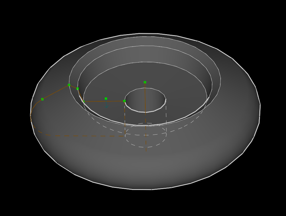
Example of a rotation body (revolution, lathe)
Constraints
Restrictions in parametric CAD systems differ from the dimension lines of ordinary computer-aided design systems. Their main difference is that changing the size value changes the sketch itself, that is, the restrictions provide an interface for two-way interaction. Restrictions can "measure" the size of a sketch, that is, perform the role of dimensions "for reference" (reference) . On the other hand, constraints can change the thumbnail itself when the value of the constraint parameter changes. This is very convenient, since in many cases the design engineer needs to create documentation not for a single product, but for a whole family of products that have a similar shape, but different values of a number of sizes. For example, it can be ordinary nuts:
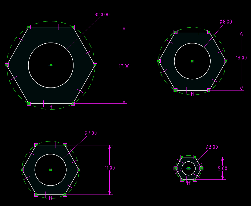
Sketches of nuts of various sizes
Automatic restructuring of the drawing when changing some parameters of the part
This is the power of parametric modeling: changing only one or several parameters, we achieve a complete restructuring of the entire model, including a three-dimensional view and sets of views on each of the drawings. You do not need to make thousands of edits, if you only need to change one size - it is enough to set its new value and the solver of geometric constraints will calculate the new coordinates of the objects, and in case of entering incorrect values it will give an error message.
Part 1: Introduction
Part 2: Sketch
Part 3: Degrees of freedom and constraint equations
Part 4: "The ways of the Solver are inscrutable" or "Newton's Wormholes"
')
Source: https://habr.com/ru/post/324160/
All Articles