FPGA Image Filtering

This article is a continuation of my previous article on motion detection on FPGAs . In it, I want to consider the implementation of three image filtering algorithms, one of which is the most important when developing a motion detector.
The need to apply filtering is caused by noise present in the frame. These noises are of a different nature: some of them are made by the camera itself, others are made by transformation algorithms, others are made by the environment, but they all create obstacles for us to detect objects.
In this project, I was faced with the noise that the camera makes and the algorithms for image binarization (Background subtraction and Frame difference). These noises manifest themselves in the form of individual points or their accumulations both locally and throughout the frame. Depending on the detection algorithm used, they can be ignored or mistaken for an object.
')
To avoid such false detection or minimizing its probability, we will apply filtering.
Median filter
The median filter, in my opinion, is the most significant for suppressing the interference I encountered while developing this project. It is just suitable for eliminating all sorts of small dispersed patches, but it is not an ideal tool because allows slightly larger areas of concentrated interference.
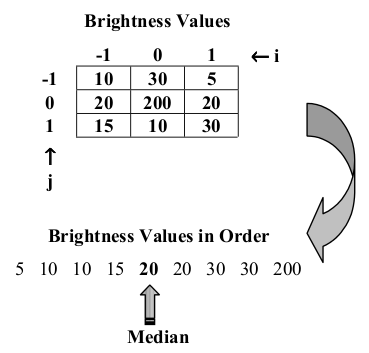
The median filter is a sliding window, in our case, a dimension of 3x3 pixels. At the input it takes 9 values (pixels), and the output gives one. The median filter works like this: sorts the input data (pixels) in ascending order and gives the median result (median).
This algorithm is quite simply implemented in the C language, but for the FPGA its implementation is somewhat different. The functional classic filter scheme is shown in the figure below. It consists of 19 basic elements.
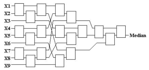
Each basic element (node) is a comparator and multiplexer.

In Verilog it looks like this:
Median filter node
module median_node #( parameter DATA_WIDTH = 8, parameter LOW_MUX = 1, // disable low output parameter HI_MUX = 1 // disable high output )( input wire [DATA_WIDTH-1:0] data_a, input wire [DATA_WIDTH-1:0] data_b, output reg [DATA_WIDTH-1:0] data_hi, output reg [DATA_WIDTH-1:0] data_lo ); wire sel0; alt_compare cmp( .dataa(data_a), .datab(data_b), .agb(sel0), .alb() ); always @(*) begin : mux_lo_hi case (sel0) 1'b0 : begin if(LOW_MUX == 1) data_lo = data_a; if(HI_MUX == 1) data_hi = data_b; end 1'b1 : begin if(LOW_MUX == 1) data_lo = data_b; if(HI_MUX == 1) data_hi = data_a; end default : begin data_lo = {DATA_WIDTH{1'b0}}; data_hi = {DATA_WIDTH{1'b0}}; end endcase end endmodule The mega- function alt_compare is used as a comparator. Further, all nodes are connected according to the scheme. Simulation of the filter in ModelSim looks like this:
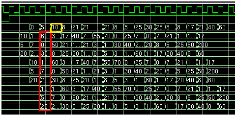
Red rectangle - input data, yellow - filter output. The output signal is delayed by 1 clock. The filter has a synchronous register output.
So, everything is clear with the median filter, it remains to deal with the 3x3 window.
3x3 sliding window
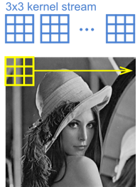
That's how it looks in action. I imagine it not as a window slides over the picture, but as a picture passes through a static window), but this does not change the essence.
In the FPGA, the window is not complicated, but it requires 2 FIFO elements the size of one line, in our case 320 elements. It looks like this:
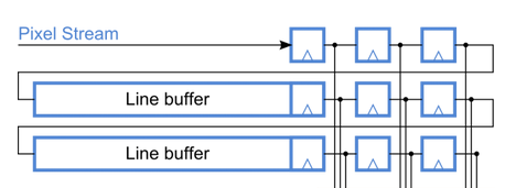
The bottom line buffer is line 1, the top line buffer is line 2, and the data of line 3 is taken directly from the stream when both FIFOs are filled in 320, in our case, elements.
In the Verilog language, this is done like this:
Line buffer
wire [7:0] line3_data = data_in; wire line2_empty; wire line2_wr_rq = (data_in_en && !line2_data_ready); wire line2_data_valid = !line2_empty; wire line2_data_ready; wire [7:0] line2_data; wire [7:0] median_out_t, sobel_out_t, gaus_out_t; reg [7:0] filter_out_r = 0; // row 3 FIFO alt_fifo_512x8 LINE2_FIFO ( .aclr(), .clock(clk), .data(line3_data), .rdreq(line1_wr_rq), .wrreq(line2_wr_rq), .almost_full(line2_data_ready), .empty(line2_empty), .full(), .q(line2_data), .usedw() ); wire line1_wr_rq = (line2_data_valid && !line1_data_ready); wire line1_data_ready; wire [7:0] line1_data; // row 2 FIFO alt_fifo_512x8 LINE1_FIFO ( .aclr(), .clock(clk), .data(line2_data), .rdreq(line1_rd_rq), .wrreq(line1_wr_rq), .almost_full(line1_data_ready), .empty(), .full(), .q(line1_data), .usedw() ); // median filter top median_top #( .DATA_WIDTH(8) ) median_top ( .clk(clk), .a0(a0), .b0(b0), .c0(c0), .a1(a1), .b1(b1), .c1(c1), .a2(a2), .b2(b2), .c2(c2), .median(median_out_t) ); Detector Sobel
The Sobel detector is an operator that calculates an approximate brightness gradient. Like the median filter, the Sobel detector is a window, in our case 3x3, function with 9 inputs and one output. In the classic version, the output of this function is the square root of the sum of squares of gradients along the X and Y axes. The result of the detector operation looks like white outlines of contrasting objects on a black background.
Filter coefficient matrix:
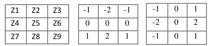
The gradient is calculated by convolving the pixel values with the coefficients of the filter matrix using the formula:
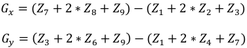
As in the case of the median filter, we need to use the formation of a 3x3 pixel window to work with this filter:
Shift register 1, 2, and 3 on the functional diagram are zapayplaynny input data from the FIFO, on Verilog looks like this:
reg [7:0] a0,b0,c0,a1,b1,c1,a2,b2,c2; always @(posedge clk or negedge nRst) if (!nRst) begin a0 <= 8'd0; b0 <= 8'd0; c0 <= 8'd0; a1 <= 8'd0; b1 <= 8'd0; c1 <= 8'd0; a2 <= 8'd0; b2 <= 8'd0; c2 <= 8'd0; end else begin a0 <= line1_data; b0 <= line2_data; c0 <= line3_data; //pipeline step 1 a1 <= a0; b1 <= b0; c1 <= c0; //pipeline step 2 a2 <= a1; b2 <= b1; c2 <= c1; end The code of the detector itself is very simple:
Edge detector
module sobel_detector (clk,z0,z1,z2,z3,z4,z5,z6,z7,z8,edge_out); input clk; input [7:0] z0,z1,z2,z3,z4,z5,z6,z7,z8; output [7:0] edge_out; reg signed [10:0] Gx; reg signed [10:0] Gy; reg signed [10:0] abs_Gx; reg signed [10:0] abs_Gy; reg [10:0] sum; always @ (posedge clk) begin //original //Gx<=((z2-z0)+((z5-z3)<<1)+(z8-z6)); //masking in x direction //Gy<=((z0-z6)+((z1-z7)<<1)+(z2-z8)); //masking in y direction // modified Gx <= (z4-z3); Gy <= (z4-z1); abs_Gx <= (Gx[10]?~Gx+1'b1:Gx);//if negative, then invert and add to make pos. abs_Gy <= (Gy[10]?~Gy+1'b1:Gy);//if negative, then invert and add to make pos. sum <= abs_Gx+abs_Gy; end //Apply Threshold assign edge_out = (sum > 20) ? 8'hff : 8'h00; endmodule sobel_detector sobel ( .clk(clk), .z0(a0), .z1(a1), .z2(a2), .z3(b0), .z4(b1), .z5(b2), .z6(c0), .z7(c1), .z8(c2), .edge_out(sobel_out_t) ); However, when testing this detector, it turned out that a lot of noise goes on its output, and instead of a beautiful white outline on a black background, we see white spots. What is the reason for such a result, I did not understand, the use of different threshold values of the classical detector did not give the desired result.
I did not search for the reasons for such a detector’s behavior, because This detector is of no practical interest to me, only informative. Instead, I modified the matrix of the Sobel operator and got an acceptable result.
Classic Matrix:
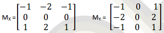
Modified Matrix:

Gauss Filter
The Gaussian filter, like the median filter, is used to eliminate noise in the frame, but it also has a side effect - blurring the image. In our project there is no such noise that needs to be removed with a Gaussian filter, therefore the implementation of this filter is of academic interest only.
Like the two previously considered filters, the Gauss operator is also a 3x3 window function.
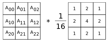
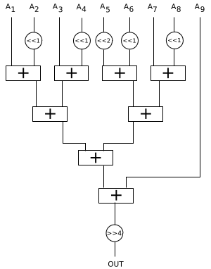
Schematically, its implementation looks like this:
Verilog code:
Gaussian filter
module gaus_filter #( parameter DATA_IN_WIDTH = 8 )( input wire [DATA_IN_WIDTH-1:0] d00_in, input wire [DATA_IN_WIDTH-1:0] d01_in, input wire [DATA_IN_WIDTH-1:0] d02_in, input wire [DATA_IN_WIDTH-1:0] d10_in, input wire [DATA_IN_WIDTH-1:0] d11_in, input wire [DATA_IN_WIDTH-1:0] d12_in, input wire [DATA_IN_WIDTH-1:0] d20_in, input wire [DATA_IN_WIDTH-1:0] d21_in, input wire [DATA_IN_WIDTH-1:0] d22_in, output wire [DATA_IN_WIDTH-1:0] ftr_out, ); wire [10:0] s1 = d00_in+(d01_in<<1)+d02_in+(d10_in<<1); wire [10:0] s2 = (d11_in<<2)+(d12_in<<1)+d20_in+(d21_in<<1); wire [11:0] s3 = s1+s2+d22_in; assign ftr_out = s3>>4; endmodule gaus_filter #( .DATA_IN_WIDTH(8) ) gaus_filter_inst( .d00_in (a0), .d01_in (a1), .d02_in (a2), .d10_in (b0), .d11_in (b1), .d12_in (b2), .d20_in (c0), .d21_in (c1), .d22_in (c2), .ftr_out (gaus_out_t), ); Filter Input Values
The absolute difference of frames of a grayscale representation for its subsequent filtering is fed to the input of the median filter, while the input of the Sobel detector and the Gauss filter is fed to the grayscale representation itself, and not its difference.
findings
The above filters were not perfected because there was no need for this project. If desired, you can implement and use more complex and resource-intensive filter designs for a specific task, and this article is for informational purposes only.
For the further development of this project, we need only a median filter.
Demonstration of the result
The right half of the screen alternately displays different modes of operation, indicated by color markers (the square in the corner of the image )
Black - grayscale view without filtering
Red - frame difference without filtering
Green - frame difference filtered by median filter
Blue - Sobel's detector
White - Gaussian filter
The first pass to the video is the work of the Frame difference algorithm. Filtering by the median filter is not very noticeable on the video. Second pass - Background subtraction. There is a noticeable difference between the difference without filtering and filtering - some separate white dots have disappeared.
After the Gauss filter, the image changes to grayscale and the difference becomes noticeable: with Gauss, the image is less sharp than just grayscale.
Materials
→ Median filter FPGA implementation
→ Sobel filter implementation
→ Gaussian filter on FPGA
Source: https://habr.com/ru/post/324070/
All Articles