Count to three
Ternary calculations
I am preparing a course of lectures on the architecture of computers for students of our university, and as a small practical warm-up, I would like to suggest that students build a primitive programmable calculator in threefold logic. Specifically, this article tells about the basic module that will be used in the construction, namely about the ternary multiplexer. In this text, I will not go beyond the simplest adder (and its implementation in hardware), the text, and so it turns out quite saturated. In subsequent articles, I will slowly tell you where this curve will lead me, since I am at the very beginning of the adventure.
- We count to three: times
- We count to three: two (memory)
- We count to three: three (counters)
- We count to three: four (one-digit computer and a three-team command system)
I chose a balanced ternary system in which one trit can represent one of the three values -1, 0 or 1. You can read about it in great detail here .
')
Any questions from the category of "why ?!" I answer in advance: "Because I can".
Building material: ternary multiplexer
Logic level
The basic building material is the ternary multiplexer. Logically, this is a five-pin thing: one of them (sel) receives the three-way selector signal, and, depending on it, one of the three inN, inO or inP input signals is output to the multiplexer (out).
On the diagrams, it is usually drawn something like this:

The demultiplexer works in a similar way: depending on the selector, one input closes at one of the three outputs. The piece of hardware that I use has bidirectional keys, so it is both a multiplexer and a demultiplexer (however, I do not use demultiplexing capabilities yet).
Implementation in the gland
The design of the piece of iron belongs to Alexander Shabarshin , I honestly whistled it entirely. The only thing I did was split the piece of metal for surface mounting, since These microcircuits are much cheaper than output ones, in China you can take them for 50 cents apiece.

Before I came across this design (by the way, there was a lot of information on ternary calculations and pieces of iron for them on the Alexander forum ), I tried to make a garden from cd4016 and cd4007, which worked, but it was extremely cumbersome and inconvenient. The use of dg403 keys gives a true ternary element without any kind of redundancy, such as coding a ternary system in a two-bit binary.
By the way, unlike many theorists, Alexander went much further, he designed and ordered his own chips, working on the ternary logic:
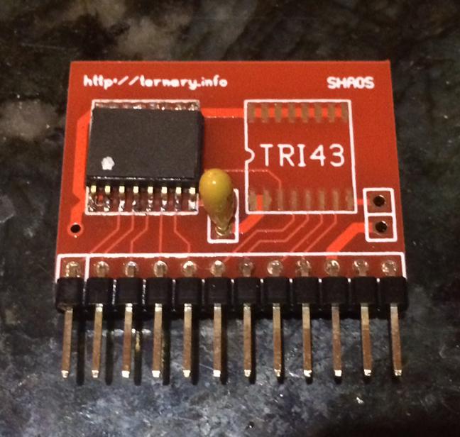
To create one TRIMUX multiplexer, Alexander used two dg403 key chips, one logic power is between -5V and 0V, and the second is between 0V and 5V, which allows you to work with a ternary signal represented by three voltage levels -5, 0 and 5V. But this leaves half the legs free, so two ternary multiplexers fit into the two dg403 chips.

How to use it? Single argument functions
Let's skip the trivial identity function, which can be obtained by applying -1, 0, 1 to the corresponding multiplexer inputs.
To begin with, let's add to the input signal A one (of course, in the -1.0,1 ring):
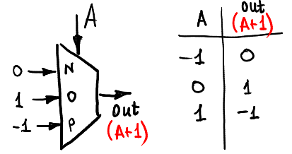
And so we can subtract a unit:
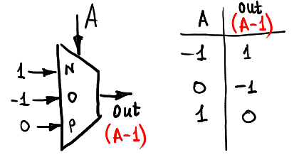
This is how we can calculate the function of one argument max (A, 0):
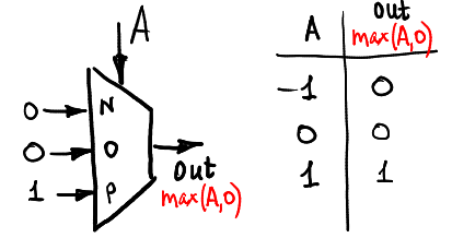
And here is min (A, 0):

Functions of two arguments: half adder
A + B
So, one multiplexer is enough for us to calculate the function of one argument. To calculate the function of two arguments, you have to use three or four multiplexers. For example, if we want to calculate the sum of two ternary signals A and B (still within the ring -1,0,1), then we can use the following scheme:
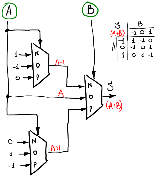
The first level of multiplexers counts the functions of one argument from signal A, and the second uses them depending on the level of signal B.
Consensus
If we want to calculate the consensus function of two ternary signals (it is -1 if A = B = -1 and 1 if A = B = 1, otherwise it is zero), then this can be done as follows:

Implementation in the gland
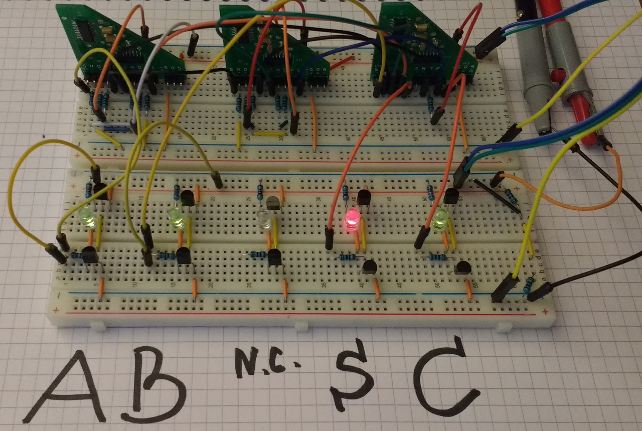
So, we just created a half adder . Depending on the two inputs A and B, it outputs two outputs S and C, which can be calculated as A + B = S + 3 * C.
Let's test it! Red diode = -1, off = 0, green = 1. Thus, this photo tells us that S = -1, C = 1, that is, 1 + 1 = -1 + 3 * 1:
This table gives all nine possible states of our half-adder, each cell lists the corresponding values of S and C. According to the links in the cells, the corresponding photographs of iron.
| S, C | B | |||
| -one | 0 | one | ||
| A | -one | 1, -1 | -1.0 | 0.0 |
| 0 | -1.0 | 0.0 | 1.0 | |
| one | 0.0 | 1.0 | -1,1 | |
The functions of the three arguments: the full adder
A full adder should take three arguments as input, not two as a half-adder. The third argument is a transfer from the lower order. So, of the three inputs A, B and Cin, we need to calculate two outputs S and Cout according to the law A + B + Cin = S + 3 * Cout.
Sum of three trit
For the function of three arguments, the idea is exactly the same as for the function of two: we apply layer-by-layer data preparation for subsequent calculations. That is, the first layer of multiplexers only accepts A, the second only B, and the last multiplexer only Cin.
This is what the S calculation scheme might look like:
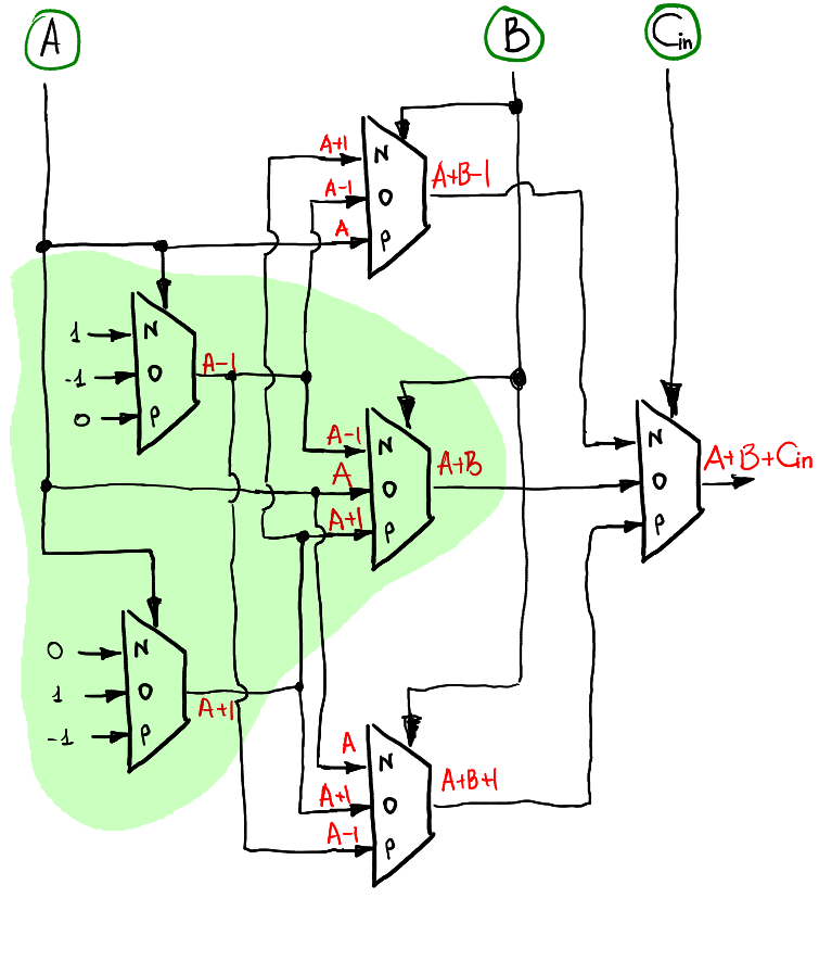
Note that when Cin = 0, then in fact this should repeat the work of the half-adder. It is logical that the half-adder is included in the full adder circuit (highlighted in green).
Result overflow
The overflow trit is considered to be completely analogous and quite the same way the scheme includes the calculation of the overflow trit at the half-adder:

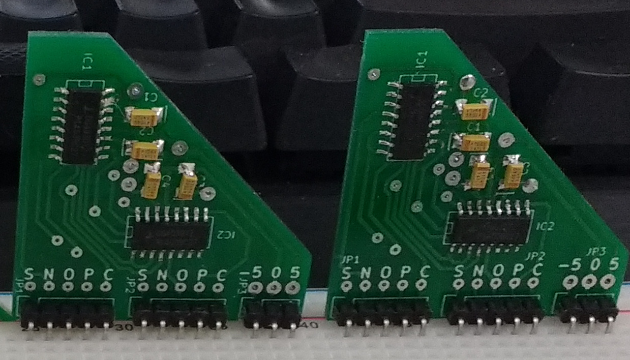
Implementation in the gland
This time I was too lazy to poke the wires on the breadboard, so I quickly spread the fee:

And blew out the age-old dust from the stocks of getinacas:
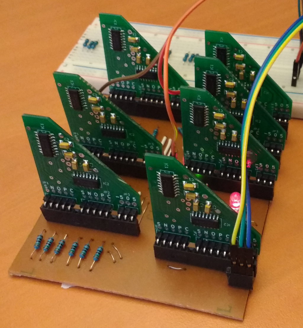
Here are all 27 possible states of the full adder, note that the middle table (which for Cin = 0 ) repeats the table for the half-adder.
| Cin = -1 | B | |||
| -one | 0 | one | ||
| A | -one | 0, -1 | 1, -1 | -1.0 |
| 0 | 1, -1 | -1.0 | 0.0 | |
| one | -1.0 | 0.0 | 1.0 | |
| Cin = 0 | B | |||
| -one | 0 | one | ||
| A | -one | 1, -1 | -1.0 | 0.0 |
| 0 | -1.0 | 0.0 | 1.0 | |
| one | 0.0 | 1.0 | -1,1 | |
| Cin = 1 | B | |||
| -one | 0 | one | ||
| A | -one | -1.0 | 0.0 | 1.0 |
| 0 | 0.0 | 1.0 | -1,1 | |
| one | 1.0 | -1,1 | 0.1 | |
What is good about a full adder is that such boards can be assembled into a sandwich until the desired bit depth is reached.
Here is a sandwich for two digits:
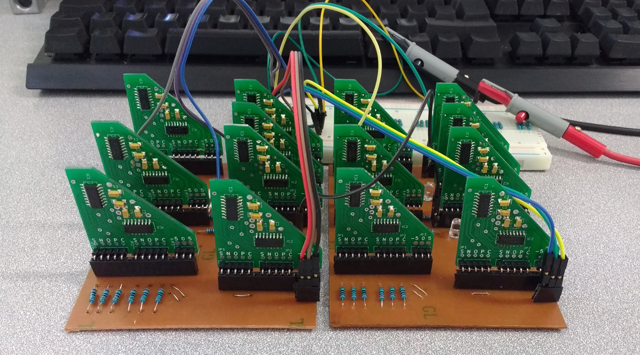
This is how he decides the example -4 + 2 (the left board is the lower order):

In fact, of course, for the youngest bit we don’t need a full adder, a half adder would be enough, because we don’t need to make a transfer to the input of a young adder. But I already disassembled the half-adder on the breadboard, and I'm too lazy to collect it back :)
Conclusion
In this article, I briefly explained what and how you can build a base for ternary calculations. In the following releases, wait for counters, memory, ALU, etc. Stay tuned!
Source: https://habr.com/ru/post/324062/
All Articles