How programs are designed: from UML to automata
Creating additional visual and documentary support for the program is a time-consuming and tedious process: it takes a lot of time and seems completely redundant if the software architecture is simple or is a reference one. However, in practice, programmers are not always faced with such tasks.
We have already described how automated programming helps to solve the problems of creating documentation and developing the logic of the entire program (using examples from primitive to complex ). Today we will talk about what other concepts and tools can be used for this purpose - and what place does automatic programming take among them.
 Andrew Butitta / Flickr / CC
')
In most cases when developing software, if the system requires revisions, programmers simply take the code and correct errors as they like, and then show the result to the customer.
Most often, the solution architecture is explained verbally or using the simplest block diagrams. A universal modeling language (UML) based on several previous standards, such as the Grady Bucha method (Booch), the Jim Rumbach method (OMT) and the Aivar Jacobson method (OOSE), was supposed to help in this matter. And certain hopes were pinned on him.
People tried to work with the UML, hoping that it would become a kind of “silver bullet”, but it did not become widely popular. Researchers identify three main obstacles that have prevented the mass distribution of state diagrams as a generally accepted means of describing algorithms and complex program behaviors.
First, to describe the behavior, in addition to state diagrams, it was proposed to use other types of diagrams, however, the rules governing their interaction were not regulated.
Secondly, no approaches were proposed for sharing diagrams describing the structure and behavior of programs. Third, diagrams for describing behavior were mainly used by developers to communicate with each other, while the purpose of UML is to make a specification and then translate it into program code.
A similar fate awaited many other solutions, which, however, are not full-fledged alternatives to UML. We are talking about the legend system for business process modeling ( BPMN ), entity-relationship models ( ERM ), data flow diagrams ( DFD ), state diagrams, etc. According to Chris Furman (Cris Fuhrman), all this is nothing more than communication tools.
However, project specifications are needed because they record the result of the design process, freeing the developer’s mind to solve other problems, and are also used as input data at the implementation stage.

Stages of developing a software system with complex behavior
Automata programming is an approach that can facilitate the specification process. During operation, graphs are created in which, under the influence of external or any other input effects, state transitions are performed and output “impulses” are formed. For this, a text version of the technical specification is first formed, in which the customer prescribes the detailed work of the desired solution.
After that, the symbols of input and output effects, sources and receivers of information are declared, and then the scheme is drawn. Transition graphs allow the customer to better understand what the programmer will do.
Having a diagram of links and a transition diagram, using a formal transformation, you can build a code that implements an automaton in a programming language. After that, the specifications become part of the system’s design documentation. Project documentation is compiled in natural language and usually contains a statement of the problem, a description of the structure and behavior of the system, examples of its use.
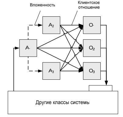
The principles of the automaton approach are also used in object-oriented programming. This is possible thanks to the concept of “automata and control objects as classes”. Such a model is adopted, for example, in the UniMod automatic programming tool. The architecture of the system with complex behavior, built according to this principle is shown in the figure below.
Comparison of a separate class to each control object leads to the fact that the efforts of developers to isolate these objects at the modeling stage do not disappear at the implementation stage. In addition, each request or command has access only to a strictly defined part of the computational state.
In general, the process of designing a system with complex behavior can be described as follows:
This algorithm does not limit the programmer in choosing a model of the development process (waterfall, iterative, cluster, etc.) and is easily modified into a multi-iteration one. However, it also allows you to make changes to an already existing object-oriented system and does not require development "from scratch."
We have already described how automated programming helps to solve the problems of creating documentation and developing the logic of the entire program (using examples from primitive to complex ). Today we will talk about what other concepts and tools can be used for this purpose - and what place does automatic programming take among them.
Andrew Butitta / Flickr / CC')
Why didn't the UML take off?
In most cases when developing software, if the system requires revisions, programmers simply take the code and correct errors as they like, and then show the result to the customer.
“Today, programming is not engineering science, but applied mathematics. At the same time, programmers immediately learn to write code, ”said Anatoly Shalyto, head of the Programming Technology Department at ITMO University.
Most often, the solution architecture is explained verbally or using the simplest block diagrams. A universal modeling language (UML) based on several previous standards, such as the Grady Bucha method (Booch), the Jim Rumbach method (OMT) and the Aivar Jacobson method (OOSE), was supposed to help in this matter. And certain hopes were pinned on him.
People tried to work with the UML, hoping that it would become a kind of “silver bullet”, but it did not become widely popular. Researchers identify three main obstacles that have prevented the mass distribution of state diagrams as a generally accepted means of describing algorithms and complex program behaviors.
First, to describe the behavior, in addition to state diagrams, it was proposed to use other types of diagrams, however, the rules governing their interaction were not regulated.
“Many people think that this language is too voluminous,” says researcher and entrepreneur Jordi Cabot. “This is due to the large number of diagrams available in UML.”
Secondly, no approaches were proposed for sharing diagrams describing the structure and behavior of programs. Third, diagrams for describing behavior were mainly used by developers to communicate with each other, while the purpose of UML is to make a specification and then translate it into program code.
A similar fate awaited many other solutions, which, however, are not full-fledged alternatives to UML. We are talking about the legend system for business process modeling ( BPMN ), entity-relationship models ( ERM ), data flow diagrams ( DFD ), state diagrams, etc. According to Chris Furman (Cris Fuhrman), all this is nothing more than communication tools.
Transition to machines
However, project specifications are needed because they record the result of the design process, freeing the developer’s mind to solve other problems, and are also used as input data at the implementation stage.
Stages of developing a software system with complex behavior
Automata programming is an approach that can facilitate the specification process. During operation, graphs are created in which, under the influence of external or any other input effects, state transitions are performed and output “impulses” are formed. For this, a text version of the technical specification is first formed, in which the customer prescribes the detailed work of the desired solution.
After that, the symbols of input and output effects, sources and receivers of information are declared, and then the scheme is drawn. Transition graphs allow the customer to better understand what the programmer will do.
Having a diagram of links and a transition diagram, using a formal transformation, you can build a code that implements an automaton in a programming language. After that, the specifications become part of the system’s design documentation. Project documentation is compiled in natural language and usually contains a statement of the problem, a description of the structure and behavior of the system, examples of its use.
Automatic description in OOP
The principles of the automaton approach are also used in object-oriented programming. This is possible thanks to the concept of “automata and control objects as classes”. Such a model is adopted, for example, in the UniMod automatic programming tool. The architecture of the system with complex behavior, built according to this principle is shown in the figure below.
Comparison of a separate class to each control object leads to the fact that the efforts of developers to isolate these objects at the modeling stage do not disappear at the implementation stage. In addition, each request or command has access only to a strictly defined part of the computational state.
In general, the process of designing a system with complex behavior can be described as follows:
- Conducting object decomposition, when the system is divided into many independent interacting entities.
- Comparison of entities with classes, definition of interfaces of classes and relations.
- Isolation of those entities that have complex behavior - the automata approach will be used to describe them.
- Setting a set of control states for each entity. Requests and commands are matched with the input and output variables of the controlling automaton, and interface components with its events. On their basis, the control automat itself is built.
- Implement human classes in the selected object-oriented language. Code generation can be performed both automatically and manually.
This algorithm does not limit the programmer in choosing a model of the development process (waterfall, iterative, cluster, etc.) and is easily modified into a multi-iteration one. However, it also allows you to make changes to an already existing object-oriented system and does not require development "from scratch."
Source: https://habr.com/ru/post/323780/
All Articles