Digitizing sound on STM32 (ADC + DMA) and encoding to Speex for transmission
 In continuation of my yesterday's article on Geektimes, I want to tell more about the implementation of digitizing and encoding sound on the STM32 microcontroller.
The article will show how to set up a project in STM32CubeMX, collect data from the ADC in two circular buffers using DMA, connect the Speex library and encode the data. Perhaps a lot of material will seem very obvious, but I hope at least someone will find it useful.
I ask under the cat.
What is Speex?
Speex is a free speech compression codec that can be used in voice-over-the-Internet (VoIP) applications. Speex codec compressed data can be stored either in the Ogg audio data storage format or transmitted directly using UDP / RTP packets. © Wiki
I learned about Speex from Speech Recognition on STM32F4-Discovery , I advise you to read, most of the code was taken from there.
')
Element base
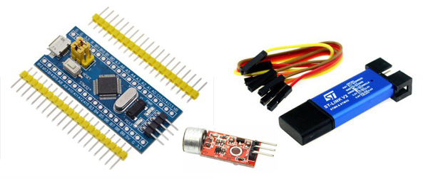 In this article, I will use the cheapest and most common debugging board based on the STM32F103C8T6 microcontroller. To her must be separately purchased programmer. The approach will not change for any Discovery card. I connected to the debugging microphone module with amplifier Max9812.
The scheme can be seen in the article specified at the very beginning. There, I turn on the ADC signal straight from the output of Max9812. To do this, on the purchased module you need to short-circuit the capacitor on the leg OUT (I feel that as a fifth point I cannot do this, but I don’t know how to do that). The input signal is obtained from the constant component of ~ 1.6V. We shoot it and in the program we bring it to the sign type for encoding.
Setting up a project in STM32CubeMX
Let's create a new project with the STM32F103C8T6 microcontroller. First of all, we indicate that we have an external quartz resonator connected. We do not need clock quartz now, although it is also on the debug board. Do not forget to enable the Serial Wire debugging interface. Then we turn on the necessary input of the ADC, I have this IN8 (see the diagram in the previous article). Well, a convenient timer by which the DMA will take data from the buffer.

After that, go to the Clock Configuration tab and configure the clocking scheme. I did this:

I set the frequency for the main periphery of the microcontroller to a maximum of 72 MHz. Timers are also set to 72 MHz, remember this value. You can do it differently, but then the timer will have to be recalculated in its own way.
Go to the Configuration tab. Here we need to configure the ADC, DMA and Timer.
The ADC is set up using timer 3 trigger. Right there in the DMA tab, select the first DMA Peripheral To Memory channel (from peripheral to memory). Priority is not important if there is nothing else in the program. The mode is Circular, the data size is Half Word (half words, 2 bytes) and the memory address will be incremented.

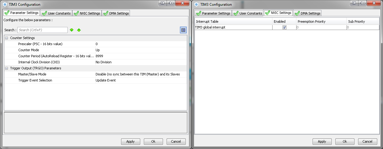
Next, set the timer. Speex supports data coding in a narrow frequency band (Narrowband, 8 kHz), wide (wideband, 16 kHz) and ultra wide (ultra-wide band, 32 kHz). We will not load the controller, we take the minimum. It turns out the controller must capture data from the ADC at a frequency of 8 kHz. The timer comes to us 72 MHz. We consider:
We adjust the timer to the value of 8999 (counting it starts from zero) and the event by the Update Event timer. We tick the global interrupt.
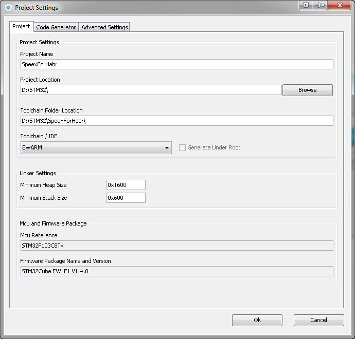
You can proceed to the generation of the project. Go to Project → Serrings . Specify the path to save the project and the size of the stack and heap. For Speex encoding, we will need approximately 0x600 and 0x1600. After that, we generate for our environment and open, I have this IAR.
 Connect the Speex library
The first thing to do is copy the folder STM32F10x_Speex_Lib with the Speex library into the project's Drivers folder. Then add the libspeex group to the project, and add the following files to it (see screenshot).
In the project properties, on the Preprocessor tab, add define HAVE_CONFIG_H and the following directories:
$ PROJ_DIR $ / .. / Drivers / STM32F10x_Speex_Lib / include
$ PROJ_DIR $ / .. / Drivers / STM32F10x_Speex_Lib / libspeex
$ PROJ_DIR $ / .. / Drivers / STM32F10x_Speex_Lib / STM32
$ PROJ_DIR $ / .. / Drivers / STM32F10x_Speex_Lib / STM32 / include
$ PROJ_DIR $ / .. / Drivers / STM32F10x_Speex_Lib / STM32 / libspeex
$ PROJ_DIR $ / .. / Drivers / STM32F10x_Speex_Lib / STM32 / libspeex / iar
Let's try to compile, everything should be fine without wiring and errors.
Programming
The main thing here is to write the code in the blocks specially allocated by USER CODE BEGIN-END, then, if you need to make changes to the Cuba project and re-generate it, all your code will be saved. I will work with the library in a separate speexx.c file. I will give his code and the code of the speexx.h header file immediately:
speexx.h
#ifdef HAVE_CONFIG_H #include "config.h" #endif #include <speex/speex.h> #include "stm32f1xx_hal.h" #define FRAME_SIZE 160 //*0.125 = 20 ( 8) #define ENCODED_FRAME_SIZE 20 // 8 #define MAX_REC_FRAMES 90 // , = MAX_REC_FRAMES*0,02 extern __IO uint16_t IN_Buffer[2][FRAME_SIZE]; extern __IO uint8_t Start_Encoding; void Speex_Init(void); void EncodingVoice(void); speexx.c
#include "speexx.h" //SPEEX variables __IO uint16_t IN_Buffer[2][FRAME_SIZE]; __IO uint8_t Start_Encoding = 0; uint8_t Index_Encoding = 0; uint32_t Encoded_Frames = 0; uint8_t REC_DATA[2][MAX_REC_FRAMES*ENCODED_FRAME_SIZE]; // uint8_t* Rec_Data_ptr = &REC_DATA[0][0]; // uint8_t* Trm_Data_ptr; // int quality = 4, complexity=1, vbr=0, enh=1;/* SPEEX PARAMETERS, MUST REMAINED UNCHANGED */ SpeexBits bits; /* Holds bits so they can be read and written by the Speex routines */ void *enc_state, *dec_state;/* Holds the states of the encoder & the decoder */ void Speex_Init(void) { /* Speex encoding initializations */ speex_bits_init(&bits); enc_state = speex_encoder_init(&speex_nb_mode); speex_encoder_ctl(enc_state, SPEEX_SET_VBR, &vbr); speex_encoder_ctl(enc_state, SPEEX_SET_QUALITY,&quality); speex_encoder_ctl(enc_state, SPEEX_SET_COMPLEXITY, &complexity); } void EncodingVoice(void) { uint8_t i; //==================== ====================== if(Start_Encoding > 0) { Index_Encoding = Start_Encoding - 1; for (i=0;i<FRAME_SIZE;i++) IN_Buffer[Index_Encoding][i]^=0x8000; /* Flush all the bits in the struct so we can encode a new frame */ speex_bits_reset(&bits); /* Encode the frame */ speex_encode_int(enc_state, (spx_int16_t*)IN_Buffer[Index_Encoding], &bits); /* Copy the bits to an array of char that can be decoded */ speex_bits_write(&bits, (char *)Rec_Data_ptr, ENCODED_FRAME_SIZE); Rec_Data_ptr += ENCODED_FRAME_SIZE; Encoded_Frames += 1; Start_Encoding = 0; } if (Encoded_Frames == MAX_REC_FRAMES) { __no_operation(); // , &REC_DATA[0][0] } if (Encoded_Frames == MAX_REC_FRAMES*2) { Rec_Data_ptr = &REC_DATA[0][0]; Encoded_Frames = 0; __no_operation(); // , &REC_DATA[1][0] } } You also need to find the timer interrupt handlers and DMA in the stm32f1xx_it.c file and supplement them by switching the Start_Encoding encoded data flag and resetting the TIM3_IRQn timer flag:
Interrupt handlers
void DMA1_Channel1_IRQHandler(void) { /* USER CODE BEGIN DMA1_Channel1_IRQn 0 */ if (DMA1->ISR & DMA_FLAG_HT1) { Start_Encoding = 1; } // DMA , if (DMA1->ISR & DMA_FLAG_TC1) { Start_Encoding = 2; } // DMA , /* USER CODE END DMA1_Channel1_IRQn 0 */ HAL_DMA_IRQHandler(&hdma_adc1); /* USER CODE BEGIN DMA1_Channel1_IRQn 1 */ /* USER CODE END DMA1_Channel1_IRQn 1 */ } /** * @brief This function handles TIM3 global interrupt. */ void TIM3_IRQHandler(void) { /* USER CODE BEGIN TIM3_IRQn 0 */ HAL_NVIC_ClearPendingIRQ(TIM3_IRQn); /* USER CODE END TIM3_IRQn 0 */ HAL_TIM_IRQHandler(&htim3); /* USER CODE BEGIN TIM3_IRQn 1 */ /* USER CODE END TIM3_IRQn 1 */ } Thus, the entire main program is reduced to starting the timer and DMA, initializing Speex and encoding it (in addition to the standard HAL initialization of course):
Speex_Init(); if(HAL_TIM_Base_Start_IT(&htim3) != HAL_OK) Error_Handler(); if(HAL_ADC_Start_DMA(&hadc1,(uint32_t*)&IN_Buffer[0],FRAME_SIZE*2) != HAL_OK) Error_Handler(); while (1) { EncodingVoice(); } And now a little run through the code. In the Speex_Init function, only the Speex encoder is initialized, the decoder must be initialized separately.
So, we set up the ADC to trigger the timer. We reset the trigger timer in the interrupt every 0.125 ms (8 kHz).
HAL_NVIC_ClearPendingIRQ(TIM3_IRQn); On DMA interruption, we have the following:
if (DMA1->ISR & DMA_FLAG_HT1) { Start_Encoding = 1; } if (DMA1->ISR & DMA_FLAG_TC1) { Start_Encoding = 2; } The DMA_FLAG_HT1 (half transfer complete) flag is raised when the DMA completed the work half (read the first half of the buffer is full), and the DMA_FLAG_TC1 (transfer complete flag) flag, respectively, when the DMA has completed the transfer (the second half is filled).
Here I came across an interesting feature that I did not know and lost time on it. On the debugger, during shutdown, DMA continues to work. Thus, the buffer always looks full and both flags are raised. It is impossible to debug the work of DMA, it does not stop.
#define FRAME_SIZE 160 //*0.125 = 20 ( 8) #define ENCODED_FRAME_SIZE 20 // #define MAX_REC_FRAMES 90 // , = MAX_REC_FRAMES*0,02 ADC sampling goes to the IN_Buffer [2] [FRAME_SIZE] double buffer, each half with 160 samples. At the output, we already get ENCODED_FRAME_SIZE bytes of data, which are sent to the REC_DATA array [2] [MAX_REC_FRAMES * ENCODED_FRAME_SIZE] at Rec_Data_ptr. The address is incremented by ENCODED_FRAME_SIZE.
After each encoding, the Encoded_Frames counter is incremented and at the moment when it becomes equal to MAX_REC_FRAMES, the first half of the output buffer becomes full and you can take data. We have time for this until the second half is filled, and so on in a circle. Data is taken from REC_DATA [0] and REC_DATA [1], respectively.
You can try to play with frame frames, quality settings, etc., but I did not.
int quality = 4, complexity=1, vbr=0, enh=1;/* SPEEX PARAMETERS, MUST REMAINED UNCHANGED */ An example of the transferred audio file is in the repository of the first article.
Materials
1. The repository with the resulting project on Github
2. Speex Codec Manual
3. Application Note from Silicon Labs
Source: https://habr.com/ru/post/323598/
All Articles