Duke Nukem 3D Source Code Analysis: Part 1

After leaving work at Amazon, I spent a lot of time reading excellent source code.
Having dealt with the incredibly wonderful idSoftware code , I started on one of the best games of all time : Duke Nukem 3D and its engine called " Build ".
')
It turned out to be a difficult experience: the engine itself is of great importance and highly valued for its speed, stability and memory consumption, but my enthusiasm has come across source code that is contradictory in terms of orderliness, compliance with recommendations and comments / documentation. While reading the code, I learned a lot about the inherited code and what allows the software to live for a long time.
As usual, I reworked my notes into an article. I hope she inspires you to read the source code and improve your skills.
I want to thank Ken Silverman for reading this article: his patience and honest answers to my letters were important to me.
Origin
Duke Nukem 3D is not one, but two code bases:
- Build Engine: Provides rendering, networking, file system, and caching services.
- Game module: uses the Build service to create a game.
Why was this separation necessary? Because in 1993, when development began, only a few people had the skills and zeal necessary to create a good 3D engine. When 3D Realms decided to write a game that would become a competitor to Doom , she needed to find powerful technology. And at this moment Ken Silverman appears on the scene.
According to his well-documented website and interviews , Ken (he was 18 at the time) wrote a 3D engine at home and sent a demo to 3D Realms for evaluation. They considered his skills promising, and concluded an agreement:
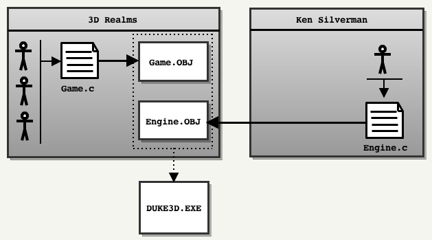
Silverman will write a new engine for 3D Realms, but will retain the source code.
It will provide only the binary static library (
Engine.OBJ ) with the header file Engine.h . For its part, the 3D Realms team will take over the work on the game module ( Game.OBJ ) and release the final executable DUKE3D.EXE .Unfortunately, the source code of both parts of the game was not open at the same time:
- The source code for the engine was released by Ken Silverman on June 20, 2000.
- The source code of the game module was released by 3D Realms on April 1, 2003.
As a result, the full source code became available only 7 years after the release of the game.
Interesting fact: the name of the engine " Build " was chosen by Ken Silverman when creating the catalog for the new engine. He used the thesaurus to find synonyms for the word "Construction" .
First contact
 Since the source code was released a long time ago (it was intended for the Watcom C / C ++ compiler and DOS systems), I tried to find something similar to Chocolate doom : a port that faithfully reproduces Duke Nukem 3D gameplay, as it was in 90 , and seamlessly compiled on modern systems.
It turned out that the Duke Nukem source code community is no longer too active: many ports are outdated again, some are created for MacOS 9 PowerPC. So far, only one ( EDuke32 ) is supported, but it has evolved too much compared to the original code.
As a result, I started working with xDuke , although it did not compile on Linux and Mac OS X (which excluded the use of Xcode: an excellent IDE for reading code and profiling).
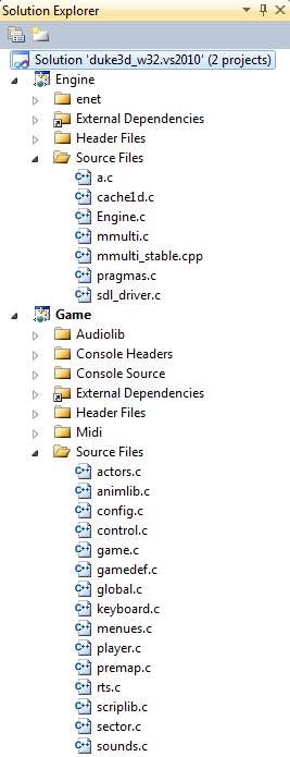
Visual Studio's xDuke faithfully reproduces the original code. It contains two projects: Engine and Game. The Engine project is compiled into a static library (
Engine.lib ), and the Game project (containing the main method) is associated with it to generate duke3D.exe .When opening VS, the engine source files look rather unfriendly due to the complex file names (
ac , cache1d.c ). These files contain something hostile to the eye and brain. Here is one of many examples in the Engine.c file (line 693) : if ((globalorientation&0x10) > 0) globalx1 = -globalx1, globaly1 = -globaly1, globalxpanning = -globalxpanning; if ((globalorientation&0x20) > 0) globalx2 = -globalx2, globaly2 = -globaly2, globalypanning = -globalypanning; globalx1 <<= globalxshift; globaly1 <<= globalxshift; globalx2 <<= globalyshift; globaly2 <<= globalyshift; globalxpanning <<= globalxshift; globalypanning <<= globalyshift; globalxpanning += (((long)sec->ceilingxpanning)<<24); globalypanning += (((long)sec->ceilingypanning)<<24); globaly1 = (-globalx1-globaly1)*halfxdimen; globalx2 = (globalx2-globaly2)*halfxdimen; Note: if the file / variable name contains a number, then this is quite possibly not a very good name!
Interesting fact: the last part of the
game.c code contains a draft of the Duke V script !Note: xDuke port uses SDL, but the advantage of the cross-platform API is lost due to WIN32 timers (
QueryPerformanceFrequency ). It seems that the SDL Timer used is too inaccurate to emulate a 120 Hz frequency in DOS.Assembly
Having dealt with the SDL and the location of the DirectX header / libraries, you can assemble the code in one click. It is very nice. The last thing left is to get the resource file
DUKE3D.GRP , and the game will start ... well, or something like that. It looks like SDL has some problems with the palette in Vista / Windows 7:
Running in windowed mode (or better on Windows 8) seems to solve the problem:
Immersion process
Now the game is working. For a few seconds, Build appears in all its splendor, showing:
- Sloping ceilings
- Realistic surroundings
- Free fall
- A sense of true 3D.
The last point was probably the most influential on players in 1996. The dive level was unsurpassed. Even when the technology reached its limit because of two-dimensional maps, Todd Replogle and Allen Blum implemented “sector effectors” that allowed to teleport a player and heighten the sense of immersion in a three-dimensional world. This feature is used in the legendary LA Meltdown map:
When a player jumps into the ventilation shaft:


The effectors of the sectors work and before the “landing” they teleport the player to a completely different place on the map:


Good games are slowly aging, and Duke Nukem is no exception: twenty years later, it is still incredibly fun to play. And now we can also study its source code!
Engine Library Overview

The engine code is in one file of 8503 lines and with 10 main functions (
Engine.c ) and in two additional files:cache1.c: contains a virtual file system (sic!) and caching system procedures.ac: C implementation of the re-created by developing code that was a highly optimized x86 assembler. The code works, but reading it is a huge meal!
Three translation modules and several functions make up a high-level architecture that is difficult to understand. Unfortunately, these are not the only difficulties that the reader will have to face.
To the interiors of the Build engine I have dedicated a whole section (see below).
Game Module Overview

The game module is entirely built on top of the engine module, the system calls of the operating system are used by the process. Everything in the game is done through Build (drawing, resource loading, file system, caching system, etc.). The only exception is the sounds and music, they are completely related to the Game .
Since I was more interested in the engine, I didn’t really understand it here. But in this module you can see more experience and organization: 15 files divide the source code into clear modules. It even has
types.h (initiator stdint.h ) to improve portability.A couple of interesting points:
game.cis a monster ofgame.clines of code.- The
menu.chas 3000 lines with “switch case”. - Most methods have “void” parameters and return “void”. Everything is done through global variables.
- Method names do not use camelCase or the NAMESPACE prefix.
- The module has a good parser / lexical analyzer, although the values of the tokens are transmitted via decimal values instead of
#define.
In general, this part of the code is easy to read and understand.
Inherited Source Code
Looking at the endless number of ports generated by Doom / Quake, I always wondered why there are so few Duke Nukem 3D ports. The same question arose when the engine was ported to OpenGL only after Ken Silverman decided to do this on his own.
Now that I looked at the code, I’d venture to explain this in the second part of this article.
Chocolate Duke Nukem 3D
I love this engine and love the game, so I couldn’t leave everything as it is: I created Chocolate Duke Nukem 3D , the port of “vanilla” source code, trying to achieve two goals in this way:
- Training: ease of reading / understanding and ease of porting.
- Reliability: the gameplay should be similar to the one we saw in 1996 on our 486s.
I hope this initiative helps to inherit the code. The most important modifications will be described in the second part of the article.
Build engine insides
Build was used in Duke Nukem 3D and many other successful games such as Shadow Warrior and Blood . At the time of release on January 29, 1996, he destroyed the Doom engine with innovative features:
- Destructible surroundings
- Sloped floors and ceilings
- Mirrors
- Opportunity to look up and down
- The ability to fly, crawl and swim under water
- Voxel objects (appeared later in “Blood”)
- Real immersion in 3D (thanks to teleports).
The crown was taken away from him in June 1996 by Quake, launched on powerful Pentiums ... but for several years Build provided high quality, designer freedom and, most importantly, good speed on most computers of that time.
The most important concept: the portal system
Most of the 3D engines divided game maps using binary space partitioning (Binary Space Partition) or Octree (Octree). Doom, for example, pre-processed each card using a time-consuming method (up to 30 minutes), which resulted in a BSP-tree, which allowed:
- Sort walls
- Determine the position
- Detect collisions.
But to please speed, one had to make concessions: the walls could not move . Build removed this restriction, it did not pre-process maps, but instead used a portal system :


On this map, the game designer drew 5 sectors (above) and connected them together, marking the walls as portals (below).
As a result, the Build world database has become ridiculously simple: one array for the sectors and one array for the walls.
  Sectors (5 records): Walls (29 records):
   ============================ ===================== ====================
   0 |  startWall: 0 numWalls: 6 0 |  Point = [x, y], nextsector = -1 // Wall in sector 0
   1 |  startWall: 6 numWalls: 8 .. |  // Wall in sector 0
   2 |  startWall: 14 numWalls: 4 .. |  // Wall in sector 0
   3 |  startWall: 18 numWalls: 3 3 |  Point = [x, y], nextsector = 1 // Portal from sector 0 to sector 1
   4 |  startWall: 21 numWalls: 8 .. |  // Wall for sector 0
   ============================ .. |  // Wall for sector 0
                                                .. |
                   First wall of sector 1 >> 6 |  Point = [x, y], nextsector = -1
                                                 7 |  Point = [x, y], nextsector = -1
                                                 8 |  Point = [x, y], nextsector = -1
                                                 9 |  Point = [x, y], nextsector = 2 // Portal from sector 1 to sector 2
                                                10 |  Point = [x, y], nextsector = -1
                                                11 |  Point = [x, y], nextsector = 0 // Portal from sector 1 to sector 0
                                                12 |  Point = [x, y], nextsector = -1
                 Last wall of sector 1 >> 13 |  Point = [x, y], nextsector = -1
                                                .. |
                                                28 |  Point = [x, y], nextsector = -1
                                                ===========================================
Another misconception about Build is that it does not emit rays: the vertices are first projected into the player’s space, and then a column / distance is generated from the viewpoint.
Duty Cycle Overview
High-level description of the frame rendering process:
- The game module transfers to the engine module the sector from which the rendering should start (usually it is the player’s sector, but it can also be a sector with a mirror).
- The engine module bypasses the portal system and visits the sectors of interest . In each visited sector:
- The walls are grouped into sets, called groups ("bunch"). They are saved to the stack.
- Sprites that are visible in this sector are defined and saved to the stack.
- Groups are processed in order from near to far: continuous walls and portals are rendered.
- Rendering stops: waiting while the game module updates visible sprites.
- Render all sprites and transparent walls in order from distant to neighbors.
- Switching buffers.
Here are each of the steps in the code:
// 1. . updatesector(int x, int y, int* lastKnownSectorID) displayrooms() { // , . ( ). drawrooms(int startingSectorID) { // "gotsector", "visited sectors". clearbufbyte(&gotsector[0],(long)((numsectors+7)>>3),0L); // umost dmost ( ). // 2. : ("bunch"). scansector(startingSectorID) { // BUNCH. // tsprite, spritesortcnt++ } // numbunches bunches. // . (O)n*n, . while ((numbunches > 0) && (numhits > 0)) { // (o) n*n for(i=1;i>numbunches;i++) { // bunchfront test } // , bunchID (closest) drawalls(closest); } } // 3. , . animatesprites() // 4. , , (, ). drawmasks() { while ((spritesortcnt > 0) && (maskwallcnt > 0)) { drawsprite or drawmaskwall } } } // . 2D- (, ) displayrest(); // 5. nextpage() An interesting fact: if you study the code, that is, a fully expanded cycle , which I used as a map.
Interesting fact: why is the buffer switching method called
nextpage() ? In the 90s, the joy of programming for VGA / VESA included the implementation of double buffering: two parts of the video memory were allocated and used in turn. Each part is called a “page”. One part was used by the VGA CRT module, and the second was updated by the engine. Switching buffers involved using the next page CRT (“next page”) by replacing the base address. You can read more about this in Chapter 23 of the book “Black Book of Graphic Programming: Bones and sinew” by Michael Abrash .Today, SDL simplifies this work with the simple flag of the
SDL_DOUBLEBUF video mode, but the method name remains as an artifact of the past.1. How to start rendering?
The absence of BSP means that it is impossible to take the point
p(x,y) and go through the nodes of the tree until we reach the leaf sector. In Build, the player’s current sector must be tracked after each position update using the updatesector(int newX, int newY, int* lastKnownSectorID) . The game module calls this engine module method very often.A naive implementation of the
updatesector would scan linearly each sector and each time check whether p(x,y) inside sector S. But the updatesector optimized by a behavioral pattern:- Writing
lastKnownSectorID, the algorithm assumes that the player has not moved very far and starts checking with thelastKnownSectorIDsector. - If point 1 failed, the algorithm checks adjacent
lastKnownSectorIDsectors using portals. - Finally, in the worst case scenario, it scans all sectors with a linear search.
On the map on the left, the last known sector of the player’s position was the sector with identifier 1 : depending on the distance the player moved, the updatesector checks in the following order:inside(x,y,1)(the player has moved not so far to leave the sector).inside(x,y,0)(the player has moved slightly to the adjacent sector).inside(x,y,2)inside(x,y,0)(the player has moved a lot: potentially checking all sectors of the game is potentially necessary).inside(x,y,1)inside(x,y,2)inside(x,y,3)inside(x,y,4)
The worst case scenario can be quite expensive. But most of the time the player / projectiles do not move very far, and the speed of the game remains high.
Details about inside
Inside is a remarkable method for two reasons:
- It can only use integers.
- It must be performed for sectors that may be concave.
I take a closer look at this method, because it perfectly demonstrates how Build works: with the help of good old vector products and XOR.
The era of fixed-point computation and the ubiquitous vector products
Since most computers in the 90s did not have a floating-point (FPU) coprocessor (386SX, 386DX and 486SX), only integers were used in Build .

The example shows a wall with end points A and B: the task is to determine whether the point is to the left or to the right.

In Chapter 61 of the book “Black Book of Programming: Frame of Reference” by Michael Abrash, this problem is solved by simple scalar product and comparison.
bool inFrontOfWall(float plan[4], float point[3]) { float dot = dotProduct(plan,point); return dot < plan[3]; } 
But in the world without floating point operations, the problem is solved by a vector product.
bool inFrontOfWall(int wall[2][2], int point[2]) { int pointVector[2], wallVector[2] ; pointVector[0] = point[0] - wall[0][0]; // pointVector[1] = point[1] - wall[0][1]; wallVector[0] = wall[1][0] - wall[0][0]; // wallVector[1] = wall[1][1] - wall[0][1]; // crossProduct Z: Z. return 0 < crossProduct(wallVector,wallVector); } An interesting fact: if you set the search string “float” in the source code of Build , then there is not a single match.
An interesting fact: the use of the
float type was popularized by Quake, because it was intended for Pentium processors and their co-processors for floating point numbers.Inside the concave polygon
Having learned how a vector product can be used to determine the position of a point relative to a wall, we can take a closer look at
inside .
An example with a concave polygon and two points: Point 1 and Point 2.
- Point 1 is considered to be outside.
- Point 2 is considered to be located inside.
The "modern" algorithm for determining the point in the polygon (point-in-polygon, PIP) is to emit a ray to the left and determine the number of crossed sides. For an odd number, the point is inside, and for even, it is outside.


Build uses a variation of this algorithm: it counts the number of edges on each side and combines the results using XOR:


Interesting fact: the Doom engine had to perform about the same tricks in R_PointOnSide . Quake used planes and floating point operations in Mod_PointInLeaf .
An interesting fact: if
inside seems difficult to you to read, I advise you to study the Chocolate Duke Nukem version , it has comments.2. Portal and opaque walls
The initial sector is transferred to the Build engine by the game module . Rendering begins with opaque walls in
drawrooms : two stages connected by a stack.
- The preprocessing stage floods the portal system (starting with
startingSectorID) and saves the walls on the stack:scansector(). - The stack consists of “bunch” elements.
- The stack elements are passed to the renderer method:
drawwalls().

What is a “bunch”?
A group is a set of walls that are considered “potentially visible.” These walls belong to the same sector and are constantly (connected by a dot) directed towards the player.
Most of the walls in the stack will be dropped, as a result only some of them are rendered on the screen.
Note: "wall proxy" is an integer that refers to a wall in the list of "potentially visible" walls. The pvWalls array contains a link to a wall in the world’s database, as well as its coordinates rotated / moved into player space and screen space.
Note: the data structure is actually more complex: only the first wall of the group is saved on the stack. The rest are in an array used as a list with references to identifiers: this is done in such a way that groups can be quickly moved up and down the stack.
An interesting fact: to mark visited "sectors", the filling process uses an array. This array must be cleared before each frame. To determine whether a sector has been visited in the current frame, it does not use the framenumber trick .
An interesting fact: in the Doom engine, quantification was used to convert angles to screen columns. In Build, the cos / sin matrix was used to convert the vertices of world space into player space.
When pouring portals, the following heuristics are used: all portals that are directed towards the player and are within the range of 90 degrees will be filled. This part is hard to understand , but it is interesting because it shows how developers were striving to save cycles everywhere:
// -> Z tempint = x1*y2-x2*y1; // , , . // : . if (((uint32_t)tempint+262144) < 524288) { //(x2-x1)*(x2-x1)+(y2-y1)*(y2-y1) is the squared length of the wall if (mulscale5(tempint,tempint) <= (x2-x1)*(x2-x1)+(y2-y1)*(y2-y1)) sectorsToVisit[numSectorsToVisit++] = nextsectnum; } Group generation
The walls inside the sector are grouped into "groups" ("bunches"). Here is a picture to explain the idea:

The figure above shows that three sectors generated four groups:
- Sector 1 generated one group containing one wall.
- Sector 2 generated one group containing three walls.
- Sector 3 generated two groups, each of which contains two walls.
Why group walls at all? Because there is no data structure in Build that allows for quick sorting. He retrieves the closest group using the process (O²), which would be very costly if performed for each wall. Resource costs are much lower than when performing for a variety of all walls.
Using groups
After filling the stack of groups, the engine starts to draw them, starting from close to far. The engine selects the first group that is not covered by another group (there is always at least one group that satisfies this condition):
/* , :( */ closest = 0; tempbuf[closest] = 1; for(i=1; i < numbunches; i++){ if ((j = bunchfront(i,closest)) < 0) continue; tempbuf[i] = 1; if (j == 0){ tempbuf[closest] = 1; closest = i; } } Note: despite the name of the variable, the group selected is not necessarily the closest.
Explanation of the principle of choice given by Ken Silverman:
2 . , x-. , . , x-. . : , . (: , , «» !) ( ) . , , , —
bunchfront- fast, complex and imperfect, so Build performs a double check before sending the result to the renderer. This disfigures the code, but as a result we get O (n) instead of O (n²).Each selected group is sent to the
drawalls(closest)renderer: this part of the code renders as many walls / floors / ceilings as possible.Visualization of walls / floors / ceilings
To understand this part, it is important to understand that everything is rendered vertically: the walls, the floor and the ceilings.
There are two clipping arrays in the renderer core. Together they track the top and bottom clipping of each column of pixels on the screen:
// - 1600x1200 #define MAXXDIM 1600 //FCS: ( x, ) short umost[MAXXDIM+1]; //FCS: ( x, ) short dmost[MAXXDIM+1]; Notes: the engine usually uses arrays of primitive types instead of an array of struct.
The engine records the vertical range of pixels, starting from the top to the bottom border. Border values move towards each other. When they determine that the pixel column is completely overlapped, the counter value decreases:

Note: most of the time, the clipping array is only partially updated: the portals leave “holes” in it.
Each wall in the group is projected into screen space, and then:
- If it is a solid wall:
- Render ceiling if it is visible.
- Render the floor if it is visible.
- Renders the wall if it is visible.
- The whole column is marked as overlapped in the clipping array.
- If this is a portal:
- Render ceiling if it is visible.
- Render the floor if it is visible.
- The engine “looks in” the following sector:
- The clipping array is updated to reflect what was drawn.

Stop condition: this cycle will continue until all groups are processed or until all columns of pixels are marked as completed.
This is much easier to understand with an example that breaks a scene, for example, a familiar hall:

On the map, portals are shown in red and solid walls in white:

Three walls of the first group are projected into the screen space: only the lower parts fall on the screen.

Therefore, the engine can render the floor vertically:

Then the engine “looks in” the sectors adjacent to each of the three walls: since their meaning is not
-1, these walls are portals. Seeing the difference between the heights of the floors, the engine understands that it is necessary to draw a step up ("UP") for each of them:
And this is all that is rendered with the first group. Now the second group is projected into the screen space.

And again only the lower part falls. This means that the engine can render the floor:

Looking into the next sector and seeing the longest portal, the engine can draw a ledge up (“STEP UP”). However, the second portal in the group leads to a lower sector: the ledge is NOT drawn.

The process is repeated. Here is a video showing the full scene:
Inside the theater:
As a result of rendering the portal door, Build painted the ledge up and the ledge down with two different textures. How is this possible with only one
picnum?:This is possible because the structure has "
picnum", it is " overpicnum" for one-sided or masked walls, and a flag that allows to "steal" the index of the bottom texture from the wall of the opposite sector. It was a hack that allowed keeping the small size of the sector structure.I compiled two other scenes in the video:
Street:
From 0:00 to 0:08: the portal of the lower line of the pavement is used to draw the vertical part of the floor.
At 0:08 the engine is looking for the level of the floor sector after the sidewalk. As it rises, the portal wall is drawn: the rendering of the pavement is complete.
From 0:18 to 0:30: a group of two pavements on the left is used to render a huge piece of floor.
Outside the theater:
This is an interesting scene in which a window appears.
The last video shows a window. Here are the details on how it is created:
Map:

The first group contains four walls that, when projected into the screen space, allow the ceiling and floor to be drawn: The

left wall of the group is the portal. After studying it turns out that the floor of the next sector is at the same height, and the ceiling is higher: there is no need to render any walls of the ledges. The second wall is opaque (marked white on the map). As a result, a full column of pixels is drawn:

The third wall is the portal. Looking at the height of the next sector, it is clear that it is lower, therefore it is necessary to render the wall of the ledge down:

The same process of “peeking” is also performed for the floor. Since it is higher, the ledge wall is drawn up:

And, finally, the last wall is processed. It is not a portal, so full columns of pixels are drawn.

An interesting fact: since the walls are drawn vertically, Build stores textures in RAM rotated 90 degrees. This greatly optimizes the use of the cache.
3. pause
At this point, all the visible solid walls are recorded in the voice-over buffer. The engine stops its work and waits for the game module to execute so that it can animate all visible sprites. These sprites are written to the following array:
#define MAXSPRITESONSCREEN 1024 extern long spritesortcnt; extern spritetype tsprite[MAXSPRITESONSCREEN]; 4. Rendering of sprites
After the game module has finished animating all the visible sprites, Build starts drawing: from the far to the near in
drawmasks().- Calculates the distance from the viewpoint to each sprite.
- Array of sprites sorted by Shell algorithm
- The engine alternately takes data from two lists (one for sprites and one for transparent walls).
- After exhausting one list, the engine tries to minimize branching and switches to a cycle that renders only one type: sprites or walls.
Profiling
Running Duke Nukem 3D through the Instruments debugger prompted me to think about what processor cycles are being spent on:
Main method:

Not surprising: most of the time is spent rendering non-transparent walls and waiting for the buffer to switch (vsync is enabled).
Displayrooms method:

93% of the time is spent drawing solid walls. 6% allotted visualization of sprites / transparent walls.
Drawrooms method:

Despite its complexity, the definition of visible surfaces (Visible Surface Determination) takes up only 0.1% of the solid wall visualization step.
The drawalls method:

* scan functions are the interface between the engine and assembler procedures:
wallscan(): wallsceilscan(): ceilings without tiltflorscan(): floor without tiltparascan(): (wallscan())grouscan(): —
:
ceilscan() florscan() , . while. , . , , , . while Doom.
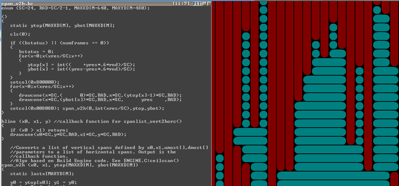
Ken sent me an evaldraw script , span_v2h.kc , showing how ceilscan () and florscan () convert a list of vertical ranges into a list of horizontal ranges:
The displayrest method:

displayrest taken from the game module . The main costs here again fall on drawing (weapons). The status bar is not drawn every frame; it is inserted only when the ammunition counter is changed.Interesting facts about VGA and VESA
Thanks to X-Mode VGA, most players started Build in 320x240 resolution. But thanks to the VESA standard, the engine also supports Super-VGA resolution. Vanilla sources are equipped with a VESA code that provides portable definition resolution and rendering.
Nostalgic can read about programming for VESA in this good guide . Today in the code leaving only the names of methods, for example
getvalidvesamodes().Sound engine
At the time, Duke3D had an impressive sound system engine. He could even mix sound effects to simulate reverb. Read more about this in reverb.c .
Inherited code
Build code is very difficult to read. I listed all the reasons for these difficulties on the Duke Nukem 3D page and Build engine: Source code issues and legacy .
Recommended reading
No Do better climbing - it's awesome!
But if you insist, then you can read id as Super-Ego: The Creation of Nukem 3D
- If you want to read about another game based on portals, then I recommend the excellent post-mortem Sean Barrett about Thief: The Dark Project.
- Many interviews with Ken Silverman:
- November 21, 2005 , classicdosgames.com ( mirror ).
- 2005 , strifestreams.com ( mirror ).
- 27 2006 , 3drealms.com ( ).
- 25 2010 misterdai.yougeezer.co.uk ( ).
- 1 2012 videogamepotpourri.blogspot.ca ( ).
[ .]
Source: https://habr.com/ru/post/323426/
All Articles