Exceptions in Windows x64. How it works. Part 2
Based on the material described in the first part of this article, we will continue the discussion of the topic of exception handling in Windows x64. And in this part we will look in detail at those areas of the PE image that are involved in the exception handling process. The described material requires knowledge of basic concepts, such as the prologue, epilogue, frame functions and understanding of basic processes, such as the actions of the prologue and epilogue, the transfer of function parameters and the return of the result of the function. If the reader is not familiar with the above, then before reading it is recommended to read the material from the first part of this article.
The article is accompanied by the implementation of the mechanism, which is located in the exceptions folder of the git repository at this address .
The section contains a table of PE image functions and information about the promotion of frames of these functions. This table is actively used by the operating system during the search for an exception handler. The size and location of the table is described in the optional data directory header (optional header data directories) of the PE image. The following sections describe the structures involved in the function description. The fields of these structures can store addresses pointing to different areas of the image. All of these addresses, unless otherwise indicated, are addresses relative to the beginning of the image.
A more detailed description of the PE image can be found in the document "Microsoft Portable Executable and Common Object File Format Specification". This article will provide only the information that is directly related to the topic under discussion.
')
The table of functions consists of elements of the type RUNTIME_FUNCTION, the definition of which is shown in Figure 1.
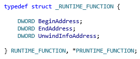
Picture 1
BeginAddress and EndAddress contain the addresses of the beginning and end of the function, respectively, and UnwindInfoAddress is the address of the spinup information structure. BeginAddress contains the address of the first byte of the function, when EndAddress contains the address of the first byte immediately after the function. This structure can also describe not the whole function, but only a part of it (chunk). This situation will be discussed in more detail in section 3.
The elements of the table are sorted in ascending order, in accordance with the initial addresses of functions / parts of functions.
As mentioned earlier, the UnwindInfoAddress field of the RUNTIME_FUNCTION structure contains the address of the UNWIND_INFO structure, which is defined below in Figure 2.
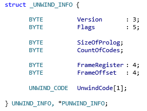
Figure 2
The Version field, as the name implies, carries a version of the promotion information. Currently the latest version is version 2.
The SizeOfProlog field contains the size of the prolog in bytes.
The FrameRegister field indicates the register number (the register numbers will be listed below), which is used as a frame pointer, and the FrameOffset field contains a value in 16-byte blocks, which is added to the RSP value when the function frame pointer is set. In fact, the frame pointer will be set to a value equal to RSP + FrameOffset * 16. The resulting offset value can be from 0 to 240. Using this intra-frame offset allows you to increase the code density, since in this case, more short instructions can be used, which use an 8-bit signed value as the offset. For example, if FrameOffset is 0, then access to the first 128 bytes of frame data can be performed using short instructions, and subsequent data is not available, since The 8-bit character value covers positive values from 0 to 127. Now, let's imagine that FrameOffset is 20, in which case the first 148 bytes of frame data can be accessed with short instructions, since Now, not only values from 0 to 127, but also values from -20 to 0 can be used as an offset. Figure 3 shows two examples of accessing a frame by the same offset, but with different FrameOffset values. Pay attention to the size of the instruction that performs access to the frame, in both cases.
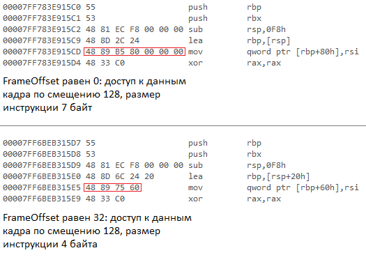
Figure 3
If FrameRegister is zero, then the frame pointer is not used, and the FrameOffset field does not carry any information. In this case, the frame pointer is the RSP.
The UnwindCode array describes the actions of the prologue. A detailed description of these codes is given in Section 4. For alignment purposes, this array always has an even number of entries. The CountOfCodes field contains the number of elements in this array. If this number is odd, then the last record of the array is not used, that is, in fact, the number of records of the array is one more than indicated in the field. The array elements are sorted in reverse order, i.e. the first element will describe the last action of the prologue.
The Flags field can contain three flags: UNW_FLAG_EHANDLER, UNW_FLAG_UHANDLER and UNW_FLAG_CHAININFO. The UNW_FLAG_EHANDLER flag indicates that the function has an exception handler (exception handler), which should be called during the search for a handler. The UNW_FLAG_UHANDLER flag indicates that the function has a spin handler (termination handler), which is to be called during spinup. The UNW_FLAG_CHAININFO flag means that this UNWIND_INFO structure is not primary, but is a continuation (chained) of the previous UNWIND_INFO structure. Setting this flag excludes setting the UNW_FLAG_EHANDLER and UNW_FLAG_UHANDLER flags, and the FrameRegister and FrameOffset fields must be identical to the primary UNWIND_INFO structure.
Immediately after the UNWIND_INFO structure, either the EXCEPTION_HANDLER structure or the RUNTIME_FUNCTION structure is located. The EXCEPTION_HANDLER structure is defined in Figure 4.
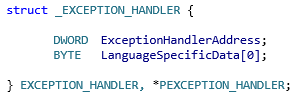
Figure 4
If the Flags field contains the set UNW_FLAG_EHANDLER or UNW_FLAG_UHANDLER bit, or both, then the EXCEPTION_HANDLER structure follows the UNWIND_INFO structure. The ExceptionHandlerAddress field contains the address of the handler to be called, and the LanguageSpecificData field contains data specific to the corresponding programming language. The prototype of the handler function, as well as the type of value returned by it, are presented below in Figure 5.
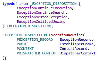
Figure 5
The ExceptionRecord parameter carries a pointer to the structure that describes the reason for the exception. The EstablisherFrame parameter carries a pointer to the frame whose handler was called. The ContextRecord parameter contains a pointer to a structure that contains the processor context at the time the exception occurred. In the process of searching for an exception handler or stack unwinding, the contents of the structure can be changed by the handlers themselves. The result of these changes will be the target context of the processor, i.e. this context will be applied to the task being performed if it is continued. The DispatcherContext parameter contains the current search context of the exception or spin-up handler. The EXCEPTION_RECORD and DISPATHCER_CONTEXT structures and the process of searching for the processor and promotion will be described in more detail in the next part of this article. The type EXCEPTION_DISPOSITION will also be discussed in the description of this process. You can find the definitions of EXCEPTION_RECORD, CONTEXT and DISPATHCER_CONTEXT in winnt.h or in the implementation of this mechanism attached to the article (under the names SExceptionRecord, SContext and SDispatcherContext, respectively).
Figure 6 shows an example of the RUNTIME_FUNCTION, UNWIND_INFO and EXCEPTION_HANDLER structures that the compiler generates for a particular function. The dotted line indicates the end of the function. The EXCEPTION_HANDLER structure is shown in the figure for completeness of the description and, despite the fact that it is not part of the UNWIND_INFO structure, is shown in the figure as part of this structure, since if it is present, it follows immediately after the UNWIND_INFO structure, as already indicated. The addresses of the beginning of the image, the beginning of the function and the end of the function are absolute; all addresses in the generated structures are relative from the beginning of the image.
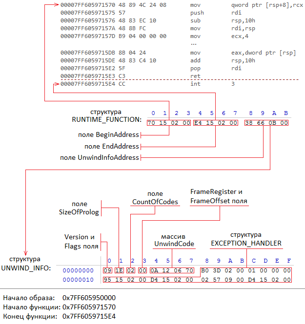
Figure 6
If the Flags field contains the UNW_FLAG_CHAININFO bit set, then the UNWIND_INFO structure is secondary (also referred to as chained), followed by the RUNTIME_FUNCTION structure. The UnwindInfoAddress field of the RUNTIME_FUNCTION structure contains the address of the previous UNWIND_INFO structure. The previous UNWIND_INFO structure, in turn, may also be secondary, but ultimately in this linked list there will be a UNWIND_INFO structure that does not have the UNW_FLAG_CHAININFO flag set. This will be the structure that belongs to the prologue of the function entry point, which is also called the primary structure. The number of connected structures can be up to 32 inclusive.
Related structures are useful in two situations.
The first situation is that the compiler can perform optimization, as a result of which it can postpone saving some constant registers. Those. their saving will not be performed in the prolog of the function entry point, but in the function body. For such code sections (in Section 2 it was already mentioned that the RUNTIME_FUNCTION structure may not describe the entire function, but only a part of it, it was just such code sections) that the compiler generates a RUNTIME_FUNCTION structure that will point to the corresponding UNWIND_INFO structure, which will describe the preservation these registers. In this case, the preservation of these registers will be performed through a normal write to the memory. Pushing onto the stack in this situation is not supported. As previously mentioned, this UNWIND_INFO structure is secondary, followed by the RUNTIME_FUNCTION structure, which contains the address of the previous UNWIND_INFO structure or the primary UNWIND_INFO structure.
The second situation: it follows from the first, by means of linked UNWIND_INFO structures, the size of the promotion information can be reduced, since There is no need to duplicate an array of promotion codes from primary and / or previous UNWIND_INFO structures.
Figure 7 shows an example of the RUNTIME_FUNCTION and UNWIND_INFO structures that the compiler generates for the function to which the previously described optimization applies. The dotted line indicates the end of the function. The RUNTIME_FUNCTION structures that follow the UNWIND_INFO structures, although they are not part of these structures, are represented as part of them, since their presence depends on the fields of the UNWIND_INFO structures. The RUNTIME_FUNCTION structures, which are marked separately in the figure, are the elements of the function table and are sorted in the table as it was indicated in section 2, in ascending order according to the initial addresses of the parts of this function. In the figure they are also presented in ascending order from bottom to top. Under each of them is represented the UNWIND_INFO structure to which they refer. The lowest RUNTIME_FUNCTION structure refers to the primary UNWIND_INFO structure. The rest refer to UNWIND_INFO structures that are secondary. Consequently, after these UNWIND_INFO structures, RUNTIME_FUNCTION structures are located, which in their content completely repeat the lowest RUNTIME_FUNCTION structure and, thus, refer to the primary UNWIND_INFO structure. It also shows from the example that the code generated by the compiler stores the RDI register not in the prolog of the function's entry point, but in the function body. This part of the code is described by the medium RUNTIME_FUNCTION structure, and in the corresponding UNWIND_INFO structure there are corresponding entries characteristic of the prolog of this section of code. The addresses of the beginning of the image, the beginning of the function and the end of the function are absolute; all addresses in the generated structures are relative from the beginning of the image.
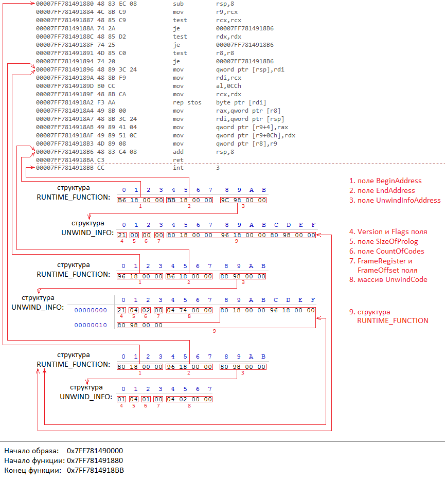
Figure 7
If the Flags field does not contain any bits set, then no structures follow the UNWIND_INFO structure.
In the previous section, the UnwindCode array of the UNWIND_INFO structure was described, which describes prolog actions. Here we look at the structure of the elements of this array, which is shown in Figure 8, as well as each code that is used in the description of the prolog actions.
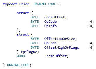
Figure 8
As can be seen from the figure, the content of the element, depending on the situation, is interpreted in one of three options.
The top structure is used when describing the prolog action.
The CodeOffset field contains an offset from the beginning of the prolog to the instruction after the instruction that performs the described action.
The OpCode field contains the code of the action being performed. Different actions take a different number of table entries, from 1 to 3. The first record is always in the format of the upper structure. The format and number of the remaining entries depends on the action code (all codes will be described below). If there is only one additional record, then this record is interpreted as a FrameOffset field. If there are two additional entries, then these entries are also interpreted as the FrameOffset field, but the first entry carries the lower 16 bits, and the second upper 16 bits of the 32-bit value. The order of the bytes in these records is direct (little endian). The purpose of these values (in the case of one and two additional entries) is described in the corresponding action codes. If the OpCode field carries the UWOP_EPILOG code, then the structure has the format of an Epilogue structure. This situation will be described in detail later. It should be noted that this code is relevant only for the structure UNWIND_INFO version 2.
The OpInfo field depends on the value of the OpCode field. It may contain the general register number that is involved in the action, the XMM register number, or a numeric value, the purpose of which is described in the corresponding action codes. The variants of interpretations of the OpInfo field not listed here are described in the corresponding action codes. Figure 9 describes the comparison of OpInfo field values with general-purpose registers and XMM registers.
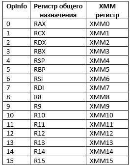
Figure 9
Some action codes contain an unsigned offset in the memory area inside the function frame. This offset is relative to the start of the function frame. If the function frame pointer is not used, then this offset is relative to the RSP value. If the frame pointer is used, then this offset is relative to the RSP value that was at the time the frame pointer was set. The value of this RSP will be equal to the Frame Pointer - FrameOffset from the UNWIND_INFO structure * 16. All offsets within the frame are multiples of 8 or 16, depending on the code of the action taken. For UWOP_SAVE_NONVOL and UWOP_SAVE_NONVOL_FAR offsets are multiples of 8, since these codes store 8-byte registers. For UWOP_SAVE_XMM128 and UWOP_SAVE_XMM128_FAR, the offset is a multiple of 16, since these codes store 16-byte registers. As mentioned in section 1 in the first part of this article, if a function has a frame pointer, saving general registers and XMM registers is done after setting the frame pointer, and therefore any unwinding codes that contain offsets in the frame area always appear in array UnwindCode before the code promotion UWOP_SET_FPREG.
The following are all valid codes. The description of the codes begins with their name, their respective numerical values and the number of records occupied by them are given in parentheses.
UWOP_PUSH_NONVOL (0; 1 record). Pushes a general-purpose register onto the stack, decreasing the RSP value by 8. The register number is indicated in the OpInfo field. As described in Section 1 of the first part of this article, the prolog first performs exactly these actions, so these codes appear last in the UnwindCode array.
UWOP_ALLOC_LARGE (1; 2 or 3 records). Selects a large area on the stack. This code has two forms. If OpInfo is 0, then the allocated size divided by 8 is stored in the next record, which allows you to allocate up to 512KB - 8. If OpInfo is 1, then the allocated size is stored in the next two records, which allows you to allocate up to 4GB - 8.
UWOP_ALLOC_SMALL (2; 1 record). Selects a small area on the stack. The allocated size is stored in the OpInfo field and is calculated as follows - OpInfo * 8 + 8, which allows you to select from 8 to 128 bytes.
Spin codes that allocate an area on the stack always use the shortest form of coding. If an area between 8 and 128 bytes is allocated, then UWOP_ALLOC_SMALL is used. If a region is allocated from 136 bytes to 512Kb - 8, then UWOP_ALLOC_LARGE is used with an OpInfo field value of 0. If an area from 512Kb to 4GB - 8 is allocated, then UWOP_ALLOC_LARGE is used with an OpInfo field value of 1.
UWOP_SET_FPREG (3; 1 record). Sets the frame pointer. The OpInfo field is reserved and not used, and the process itself is described in detail in Section 3, when describing the FrameRegister field of the UNWIND_INFO structure.
UWOP_SAVE_NONVOL (4; 2 records). Stores a general register on the stack with instructions for writing to memory. The value is saved to a previously selected area. The number of the register to be saved is specified in OpInfo. The offset from the beginning of the frame, divided by 8, is stored in the next record.
UWOP_SAVE_NONVOL_FAR (5; 3 records). Stores a general-purpose register on the stack, using a long offset, with memory write instructions. The value is saved to a previously selected area. The number of the register to be saved is specified in OpInfo. The offset from the beginning of the frame is stored in the following two entries.
UWOP_EPILOG (6; 2 records). For version 1 of the UNWIND_INFO structure, this code was called UWOP_SAVE_XMM and occupied 2 records, it saved the lower 64 bits of the XMM register, but was later removed and is now skipped. Practically this code has never been used. For version 2 of the UNWIND_INFO structure, this code is called UWOP_EPILOG, takes 2 entries and describes the function epilogue. A detailed description of this code will be given below.
UWOP_SPARE_CODE (7; 3 records). For version 1 of the UNWIND_INFO structure, this code was called UWOP_SAVE_XMM_FAR and occupied 3 entries, it saved the lower 64 bits of the XMM register, but was later removed and is now skipped. Practically this code has never been used. For version 2 of the UNWIND_INFO structure, this code is called UWOP_SPARE_CODE, takes 3 entries and has no meaning.
UWOP_SAVE_XMM128 (8; 2 records). Stores all 128 bits of the XMM register in the stack. The number of the register to be saved is specified in OpInfo. The offset from the beginning of the frame, divided by 16, is stored in the next record.
UWOP_SAVE_XMM128_FAR (9; 3 records). Stores all 128 bits of the XMM register in the stack. The number of the register to be saved is specified in OpInfo. The offset from the beginning of the frame is stored in the following two entries.
UWOP_PUSH_MACHFRAME (10; 1 record). Pushes the engine frame. The entry is used to indicate the action of a hardware interrupt or exception. This code has two forms. If OpInfo is 0, this means that the processor has pushed the following registers into the stack: SS, old RSP, EFLAGS, CS, RIP. If OpInfo is 1, then this means that the processor pushed the same registers onto the stack, as if OpInfo were 0, but pushed the error code onto the stack before pushing them. Each of the values after pushing is located at an address multiple of 8. If the value is less than 8 bytes, then the older unused bytes are zeroed. If this code is used, then it appears in the UnwindCode array the most recent. If OpInfo is 0, then the RSP value decreases by 40, otherwise by 48. In Figure 10 both cases are depicted, and the arrow indicates the direction of growth of the stack.

Figure 10
Figure 11 shows an example of the UnwindCode array for the prologue shown in Figure 1 in the first part of this article.
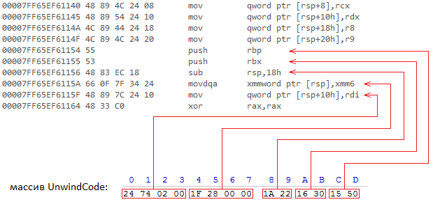
Figure 11
Figure 12 shows an example of the UnwindCode array for the prologue shown in Figure 3 in the first part of this article. It should be mentioned that for the UWOP_SET_FPREG code, all the necessary information is in the FrameRegister and FrameOffset fields of the UNWIND_INFO structure.
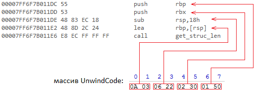
Figure 12
Now consider UWOP_EPILOG in more detail.
As noted earlier, this entry is present only in the UNWIND_INFO version 2 structure. The record has the format of the Epilogue structure, which is shown in Figure 8. This code describes the location of the function epilogue. This allows you to determine whether the processor executed the epilogue code at the time of the interruption / exclusion not by program code, as described in Section 1 in the first part of this article, but from the UnwindCode array.
A function may have several epilogs, therefore, there will be one UWOP_EPILOG entry for each epilogue. If the UWOP_EPILOG code is used, then this record appears first in the UnwindCode array, followed by at least one more UWOP_EPILOG record. The first UWOP_EPILOG entry, in the OffsetLowOrSize field, describes the size of the epilog. If bit 0 of the OffsetHighOrFlags field of the first UWOP_EPILOG record is set, then the OffsetLowOrSize field is not only the size but also an offset to the epilog of the function, which can only be when the epilog is at the end of the function / part of the function. The offset to the epilogue in these entries is reversed, i.e. it is not added to the address of the beginning of the function / part of the function, but is subtracted from the address of the end of the function / part of the function to calculate the address of the beginning of the epilogue. As already noted in section 2, the addresses of the beginning and end of the function / part of the function are contained in the BeginAddress and EndAddress fields of the RUNTIME_FUNCTION structure. If bit 0 of the OffsetHighOrFlags field of the first UWOP_EPILOG record is not set, then this record is followed by the next UWOP_EPILOG record, the OffsetLowOrSize and OffsetHighOrFlags fields of which contain the lower 8 bits and the upper 4 bits of the offset, respectively. Just as it was already noted, for each epilog of the function there is an additional UWOP_EPILOG record; in this case, as in the previous one, the OffsetLowOrSize and OffsetHighOrFlags fields form a 12-bit offset from the end of the function / part of the function.
Since The UWOP_SAVE_XMM code takes up two records, the number of records that UWOP_EPILOG takes is always even, and the last record may not be used. If this is the case, then the OffsetLowOrSize and OffsetHighOrFlags fields of the UWOP_EPILOG entry are 0.
Figure 13 shows an example of an UnwindCode array for a function that has one epilog located at the end of the function. The addresses of the beginning and end of the function are absolute.
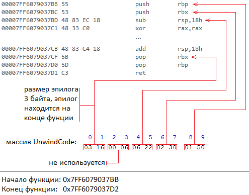
Figure 13
As shown in Figure 13, despite the fact that the function allocates an area in the stack in the prologue, the beginning of the epilogue is considered to be the place where the general registers start popping out of the stack, rather than freeing the memory from the stack. An explanation for this will be given in the next part of this article.
This is embedded in the concept of UWOP_EPILOG codes. An epilogue may consist of instructions for ejecting general-purpose registers, followed by instructions that increase the RSP by 8 (as already noted in section 1 of the first part of this article), and return instructions.
Figure 14 shows an example of an UnwindCode array for a function that has three epilogs. The addresses of the beginning and end of the function are absolute.

Figure 14
In this part of the article we have finished to consider the necessary theoretical material. In the next part of the article, we will discuss the auxiliary functions and structures that are introduced into the operating system to simplify working with the PE image structures. Then we look at the process of raising and handling the exception, as well as how these helper functions are used in the process.
The article is accompanied by the implementation of the mechanism, which is located in the exceptions folder of the git repository at this address .
1. .pdata section of PE image
The section contains a table of PE image functions and information about the promotion of frames of these functions. This table is actively used by the operating system during the search for an exception handler. The size and location of the table is described in the optional data directory header (optional header data directories) of the PE image. The following sections describe the structures involved in the function description. The fields of these structures can store addresses pointing to different areas of the image. All of these addresses, unless otherwise indicated, are addresses relative to the beginning of the image.
A more detailed description of the PE image can be found in the document "Microsoft Portable Executable and Common Object File Format Specification". This article will provide only the information that is directly related to the topic under discussion.
')
2. Table of functions
The table of functions consists of elements of the type RUNTIME_FUNCTION, the definition of which is shown in Figure 1.
Picture 1
BeginAddress and EndAddress contain the addresses of the beginning and end of the function, respectively, and UnwindInfoAddress is the address of the spinup information structure. BeginAddress contains the address of the first byte of the function, when EndAddress contains the address of the first byte immediately after the function. This structure can also describe not the whole function, but only a part of it (chunk). This situation will be discussed in more detail in section 3.
The elements of the table are sorted in ascending order, in accordance with the initial addresses of functions / parts of functions.
3. Information about promotion
As mentioned earlier, the UnwindInfoAddress field of the RUNTIME_FUNCTION structure contains the address of the UNWIND_INFO structure, which is defined below in Figure 2.
Figure 2
The Version field, as the name implies, carries a version of the promotion information. Currently the latest version is version 2.
The SizeOfProlog field contains the size of the prolog in bytes.
The FrameRegister field indicates the register number (the register numbers will be listed below), which is used as a frame pointer, and the FrameOffset field contains a value in 16-byte blocks, which is added to the RSP value when the function frame pointer is set. In fact, the frame pointer will be set to a value equal to RSP + FrameOffset * 16. The resulting offset value can be from 0 to 240. Using this intra-frame offset allows you to increase the code density, since in this case, more short instructions can be used, which use an 8-bit signed value as the offset. For example, if FrameOffset is 0, then access to the first 128 bytes of frame data can be performed using short instructions, and subsequent data is not available, since The 8-bit character value covers positive values from 0 to 127. Now, let's imagine that FrameOffset is 20, in which case the first 148 bytes of frame data can be accessed with short instructions, since Now, not only values from 0 to 127, but also values from -20 to 0 can be used as an offset. Figure 3 shows two examples of accessing a frame by the same offset, but with different FrameOffset values. Pay attention to the size of the instruction that performs access to the frame, in both cases.
Figure 3
If FrameRegister is zero, then the frame pointer is not used, and the FrameOffset field does not carry any information. In this case, the frame pointer is the RSP.
The UnwindCode array describes the actions of the prologue. A detailed description of these codes is given in Section 4. For alignment purposes, this array always has an even number of entries. The CountOfCodes field contains the number of elements in this array. If this number is odd, then the last record of the array is not used, that is, in fact, the number of records of the array is one more than indicated in the field. The array elements are sorted in reverse order, i.e. the first element will describe the last action of the prologue.
The Flags field can contain three flags: UNW_FLAG_EHANDLER, UNW_FLAG_UHANDLER and UNW_FLAG_CHAININFO. The UNW_FLAG_EHANDLER flag indicates that the function has an exception handler (exception handler), which should be called during the search for a handler. The UNW_FLAG_UHANDLER flag indicates that the function has a spin handler (termination handler), which is to be called during spinup. The UNW_FLAG_CHAININFO flag means that this UNWIND_INFO structure is not primary, but is a continuation (chained) of the previous UNWIND_INFO structure. Setting this flag excludes setting the UNW_FLAG_EHANDLER and UNW_FLAG_UHANDLER flags, and the FrameRegister and FrameOffset fields must be identical to the primary UNWIND_INFO structure.
Immediately after the UNWIND_INFO structure, either the EXCEPTION_HANDLER structure or the RUNTIME_FUNCTION structure is located. The EXCEPTION_HANDLER structure is defined in Figure 4.
Figure 4
If the Flags field contains the set UNW_FLAG_EHANDLER or UNW_FLAG_UHANDLER bit, or both, then the EXCEPTION_HANDLER structure follows the UNWIND_INFO structure. The ExceptionHandlerAddress field contains the address of the handler to be called, and the LanguageSpecificData field contains data specific to the corresponding programming language. The prototype of the handler function, as well as the type of value returned by it, are presented below in Figure 5.
Figure 5
The ExceptionRecord parameter carries a pointer to the structure that describes the reason for the exception. The EstablisherFrame parameter carries a pointer to the frame whose handler was called. The ContextRecord parameter contains a pointer to a structure that contains the processor context at the time the exception occurred. In the process of searching for an exception handler or stack unwinding, the contents of the structure can be changed by the handlers themselves. The result of these changes will be the target context of the processor, i.e. this context will be applied to the task being performed if it is continued. The DispatcherContext parameter contains the current search context of the exception or spin-up handler. The EXCEPTION_RECORD and DISPATHCER_CONTEXT structures and the process of searching for the processor and promotion will be described in more detail in the next part of this article. The type EXCEPTION_DISPOSITION will also be discussed in the description of this process. You can find the definitions of EXCEPTION_RECORD, CONTEXT and DISPATHCER_CONTEXT in winnt.h or in the implementation of this mechanism attached to the article (under the names SExceptionRecord, SContext and SDispatcherContext, respectively).
Figure 6 shows an example of the RUNTIME_FUNCTION, UNWIND_INFO and EXCEPTION_HANDLER structures that the compiler generates for a particular function. The dotted line indicates the end of the function. The EXCEPTION_HANDLER structure is shown in the figure for completeness of the description and, despite the fact that it is not part of the UNWIND_INFO structure, is shown in the figure as part of this structure, since if it is present, it follows immediately after the UNWIND_INFO structure, as already indicated. The addresses of the beginning of the image, the beginning of the function and the end of the function are absolute; all addresses in the generated structures are relative from the beginning of the image.
Figure 6
If the Flags field contains the UNW_FLAG_CHAININFO bit set, then the UNWIND_INFO structure is secondary (also referred to as chained), followed by the RUNTIME_FUNCTION structure. The UnwindInfoAddress field of the RUNTIME_FUNCTION structure contains the address of the previous UNWIND_INFO structure. The previous UNWIND_INFO structure, in turn, may also be secondary, but ultimately in this linked list there will be a UNWIND_INFO structure that does not have the UNW_FLAG_CHAININFO flag set. This will be the structure that belongs to the prologue of the function entry point, which is also called the primary structure. The number of connected structures can be up to 32 inclusive.
Related structures are useful in two situations.
The first situation is that the compiler can perform optimization, as a result of which it can postpone saving some constant registers. Those. their saving will not be performed in the prolog of the function entry point, but in the function body. For such code sections (in Section 2 it was already mentioned that the RUNTIME_FUNCTION structure may not describe the entire function, but only a part of it, it was just such code sections) that the compiler generates a RUNTIME_FUNCTION structure that will point to the corresponding UNWIND_INFO structure, which will describe the preservation these registers. In this case, the preservation of these registers will be performed through a normal write to the memory. Pushing onto the stack in this situation is not supported. As previously mentioned, this UNWIND_INFO structure is secondary, followed by the RUNTIME_FUNCTION structure, which contains the address of the previous UNWIND_INFO structure or the primary UNWIND_INFO structure.
The second situation: it follows from the first, by means of linked UNWIND_INFO structures, the size of the promotion information can be reduced, since There is no need to duplicate an array of promotion codes from primary and / or previous UNWIND_INFO structures.
Figure 7 shows an example of the RUNTIME_FUNCTION and UNWIND_INFO structures that the compiler generates for the function to which the previously described optimization applies. The dotted line indicates the end of the function. The RUNTIME_FUNCTION structures that follow the UNWIND_INFO structures, although they are not part of these structures, are represented as part of them, since their presence depends on the fields of the UNWIND_INFO structures. The RUNTIME_FUNCTION structures, which are marked separately in the figure, are the elements of the function table and are sorted in the table as it was indicated in section 2, in ascending order according to the initial addresses of the parts of this function. In the figure they are also presented in ascending order from bottom to top. Under each of them is represented the UNWIND_INFO structure to which they refer. The lowest RUNTIME_FUNCTION structure refers to the primary UNWIND_INFO structure. The rest refer to UNWIND_INFO structures that are secondary. Consequently, after these UNWIND_INFO structures, RUNTIME_FUNCTION structures are located, which in their content completely repeat the lowest RUNTIME_FUNCTION structure and, thus, refer to the primary UNWIND_INFO structure. It also shows from the example that the code generated by the compiler stores the RDI register not in the prolog of the function's entry point, but in the function body. This part of the code is described by the medium RUNTIME_FUNCTION structure, and in the corresponding UNWIND_INFO structure there are corresponding entries characteristic of the prolog of this section of code. The addresses of the beginning of the image, the beginning of the function and the end of the function are absolute; all addresses in the generated structures are relative from the beginning of the image.
Figure 7
If the Flags field does not contain any bits set, then no structures follow the UNWIND_INFO structure.
4. Promotion codes
In the previous section, the UnwindCode array of the UNWIND_INFO structure was described, which describes prolog actions. Here we look at the structure of the elements of this array, which is shown in Figure 8, as well as each code that is used in the description of the prolog actions.
Figure 8
As can be seen from the figure, the content of the element, depending on the situation, is interpreted in one of three options.
The top structure is used when describing the prolog action.
The CodeOffset field contains an offset from the beginning of the prolog to the instruction after the instruction that performs the described action.
The OpCode field contains the code of the action being performed. Different actions take a different number of table entries, from 1 to 3. The first record is always in the format of the upper structure. The format and number of the remaining entries depends on the action code (all codes will be described below). If there is only one additional record, then this record is interpreted as a FrameOffset field. If there are two additional entries, then these entries are also interpreted as the FrameOffset field, but the first entry carries the lower 16 bits, and the second upper 16 bits of the 32-bit value. The order of the bytes in these records is direct (little endian). The purpose of these values (in the case of one and two additional entries) is described in the corresponding action codes. If the OpCode field carries the UWOP_EPILOG code, then the structure has the format of an Epilogue structure. This situation will be described in detail later. It should be noted that this code is relevant only for the structure UNWIND_INFO version 2.
The OpInfo field depends on the value of the OpCode field. It may contain the general register number that is involved in the action, the XMM register number, or a numeric value, the purpose of which is described in the corresponding action codes. The variants of interpretations of the OpInfo field not listed here are described in the corresponding action codes. Figure 9 describes the comparison of OpInfo field values with general-purpose registers and XMM registers.
Figure 9
Some action codes contain an unsigned offset in the memory area inside the function frame. This offset is relative to the start of the function frame. If the function frame pointer is not used, then this offset is relative to the RSP value. If the frame pointer is used, then this offset is relative to the RSP value that was at the time the frame pointer was set. The value of this RSP will be equal to the Frame Pointer - FrameOffset from the UNWIND_INFO structure * 16. All offsets within the frame are multiples of 8 or 16, depending on the code of the action taken. For UWOP_SAVE_NONVOL and UWOP_SAVE_NONVOL_FAR offsets are multiples of 8, since these codes store 8-byte registers. For UWOP_SAVE_XMM128 and UWOP_SAVE_XMM128_FAR, the offset is a multiple of 16, since these codes store 16-byte registers. As mentioned in section 1 in the first part of this article, if a function has a frame pointer, saving general registers and XMM registers is done after setting the frame pointer, and therefore any unwinding codes that contain offsets in the frame area always appear in array UnwindCode before the code promotion UWOP_SET_FPREG.
The following are all valid codes. The description of the codes begins with their name, their respective numerical values and the number of records occupied by them are given in parentheses.
UWOP_PUSH_NONVOL (0; 1 record). Pushes a general-purpose register onto the stack, decreasing the RSP value by 8. The register number is indicated in the OpInfo field. As described in Section 1 of the first part of this article, the prolog first performs exactly these actions, so these codes appear last in the UnwindCode array.
UWOP_ALLOC_LARGE (1; 2 or 3 records). Selects a large area on the stack. This code has two forms. If OpInfo is 0, then the allocated size divided by 8 is stored in the next record, which allows you to allocate up to 512KB - 8. If OpInfo is 1, then the allocated size is stored in the next two records, which allows you to allocate up to 4GB - 8.
UWOP_ALLOC_SMALL (2; 1 record). Selects a small area on the stack. The allocated size is stored in the OpInfo field and is calculated as follows - OpInfo * 8 + 8, which allows you to select from 8 to 128 bytes.
Spin codes that allocate an area on the stack always use the shortest form of coding. If an area between 8 and 128 bytes is allocated, then UWOP_ALLOC_SMALL is used. If a region is allocated from 136 bytes to 512Kb - 8, then UWOP_ALLOC_LARGE is used with an OpInfo field value of 0. If an area from 512Kb to 4GB - 8 is allocated, then UWOP_ALLOC_LARGE is used with an OpInfo field value of 1.
UWOP_SET_FPREG (3; 1 record). Sets the frame pointer. The OpInfo field is reserved and not used, and the process itself is described in detail in Section 3, when describing the FrameRegister field of the UNWIND_INFO structure.
UWOP_SAVE_NONVOL (4; 2 records). Stores a general register on the stack with instructions for writing to memory. The value is saved to a previously selected area. The number of the register to be saved is specified in OpInfo. The offset from the beginning of the frame, divided by 8, is stored in the next record.
UWOP_SAVE_NONVOL_FAR (5; 3 records). Stores a general-purpose register on the stack, using a long offset, with memory write instructions. The value is saved to a previously selected area. The number of the register to be saved is specified in OpInfo. The offset from the beginning of the frame is stored in the following two entries.
UWOP_EPILOG (6; 2 records). For version 1 of the UNWIND_INFO structure, this code was called UWOP_SAVE_XMM and occupied 2 records, it saved the lower 64 bits of the XMM register, but was later removed and is now skipped. Practically this code has never been used. For version 2 of the UNWIND_INFO structure, this code is called UWOP_EPILOG, takes 2 entries and describes the function epilogue. A detailed description of this code will be given below.
UWOP_SPARE_CODE (7; 3 records). For version 1 of the UNWIND_INFO structure, this code was called UWOP_SAVE_XMM_FAR and occupied 3 entries, it saved the lower 64 bits of the XMM register, but was later removed and is now skipped. Practically this code has never been used. For version 2 of the UNWIND_INFO structure, this code is called UWOP_SPARE_CODE, takes 3 entries and has no meaning.
UWOP_SAVE_XMM128 (8; 2 records). Stores all 128 bits of the XMM register in the stack. The number of the register to be saved is specified in OpInfo. The offset from the beginning of the frame, divided by 16, is stored in the next record.
UWOP_SAVE_XMM128_FAR (9; 3 records). Stores all 128 bits of the XMM register in the stack. The number of the register to be saved is specified in OpInfo. The offset from the beginning of the frame is stored in the following two entries.
UWOP_PUSH_MACHFRAME (10; 1 record). Pushes the engine frame. The entry is used to indicate the action of a hardware interrupt or exception. This code has two forms. If OpInfo is 0, this means that the processor has pushed the following registers into the stack: SS, old RSP, EFLAGS, CS, RIP. If OpInfo is 1, then this means that the processor pushed the same registers onto the stack, as if OpInfo were 0, but pushed the error code onto the stack before pushing them. Each of the values after pushing is located at an address multiple of 8. If the value is less than 8 bytes, then the older unused bytes are zeroed. If this code is used, then it appears in the UnwindCode array the most recent. If OpInfo is 0, then the RSP value decreases by 40, otherwise by 48. In Figure 10 both cases are depicted, and the arrow indicates the direction of growth of the stack.
Figure 10
Figure 11 shows an example of the UnwindCode array for the prologue shown in Figure 1 in the first part of this article.
Figure 11
Figure 12 shows an example of the UnwindCode array for the prologue shown in Figure 3 in the first part of this article. It should be mentioned that for the UWOP_SET_FPREG code, all the necessary information is in the FrameRegister and FrameOffset fields of the UNWIND_INFO structure.
Figure 12
Now consider UWOP_EPILOG in more detail.
As noted earlier, this entry is present only in the UNWIND_INFO version 2 structure. The record has the format of the Epilogue structure, which is shown in Figure 8. This code describes the location of the function epilogue. This allows you to determine whether the processor executed the epilogue code at the time of the interruption / exclusion not by program code, as described in Section 1 in the first part of this article, but from the UnwindCode array.
A function may have several epilogs, therefore, there will be one UWOP_EPILOG entry for each epilogue. If the UWOP_EPILOG code is used, then this record appears first in the UnwindCode array, followed by at least one more UWOP_EPILOG record. The first UWOP_EPILOG entry, in the OffsetLowOrSize field, describes the size of the epilog. If bit 0 of the OffsetHighOrFlags field of the first UWOP_EPILOG record is set, then the OffsetLowOrSize field is not only the size but also an offset to the epilog of the function, which can only be when the epilog is at the end of the function / part of the function. The offset to the epilogue in these entries is reversed, i.e. it is not added to the address of the beginning of the function / part of the function, but is subtracted from the address of the end of the function / part of the function to calculate the address of the beginning of the epilogue. As already noted in section 2, the addresses of the beginning and end of the function / part of the function are contained in the BeginAddress and EndAddress fields of the RUNTIME_FUNCTION structure. If bit 0 of the OffsetHighOrFlags field of the first UWOP_EPILOG record is not set, then this record is followed by the next UWOP_EPILOG record, the OffsetLowOrSize and OffsetHighOrFlags fields of which contain the lower 8 bits and the upper 4 bits of the offset, respectively. Just as it was already noted, for each epilog of the function there is an additional UWOP_EPILOG record; in this case, as in the previous one, the OffsetLowOrSize and OffsetHighOrFlags fields form a 12-bit offset from the end of the function / part of the function.
Since The UWOP_SAVE_XMM code takes up two records, the number of records that UWOP_EPILOG takes is always even, and the last record may not be used. If this is the case, then the OffsetLowOrSize and OffsetHighOrFlags fields of the UWOP_EPILOG entry are 0.
Figure 13 shows an example of an UnwindCode array for a function that has one epilog located at the end of the function. The addresses of the beginning and end of the function are absolute.
Figure 13
As shown in Figure 13, despite the fact that the function allocates an area in the stack in the prologue, the beginning of the epilogue is considered to be the place where the general registers start popping out of the stack, rather than freeing the memory from the stack. An explanation for this will be given in the next part of this article.
This is embedded in the concept of UWOP_EPILOG codes. An epilogue may consist of instructions for ejecting general-purpose registers, followed by instructions that increase the RSP by 8 (as already noted in section 1 of the first part of this article), and return instructions.
Figure 14 shows an example of an UnwindCode array for a function that has three epilogs. The addresses of the beginning and end of the function are absolute.
Figure 14
Conclusion
In this part of the article we have finished to consider the necessary theoretical material. In the next part of the article, we will discuss the auxiliary functions and structures that are introduced into the operating system to simplify working with the PE image structures. Then we look at the process of raising and handling the exception, as well as how these helper functions are used in the process.
Source: https://habr.com/ru/post/322956/
All Articles