Doom engine source code analysis: rendering
From designer to player screen
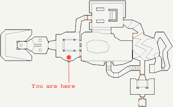
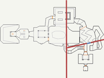
Maps were designed by a level designer in 2D using the Doom Editor (DoomED). LINEDEFS described closed sectors (SECTORS in the source code), and the third dimension (height) was indicated sector-by-sector. The first level of Doom E1M1 looks like this:
')
After completion of work on the map, it is cut using the binary space partitioning method (BSP). LINEDEF chose recursively and turned their planes into cutting planes. That is, LINEDEF was cut into segments (SEGS) until only convex subsectors remained (SSECTOR in the code).
Interesting fact: Both DoomED and iBSP were written on ... Objective-C on NextStep workstations. Fifteen years later, the same language in the same operating system performs the game on a mobile device! [approx. Trans .: in 2010, Doom came out on the iPhone] I worked a little bit as a web archaeologist and I managed to find the source code for idbsp. It is worth a look .
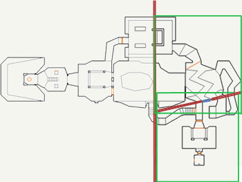
Below is an example of a recursive separation of a first-level map.
Recursion level 1
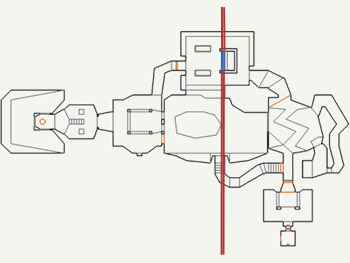
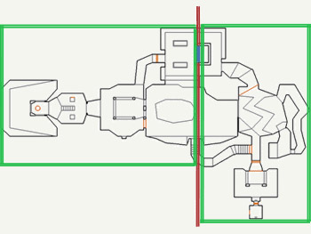
Blue marked the selected wall, turned into a cutting plane (red). The secant plane was chosen in such a way as to balance the BSP-tree, as well as to limit the number of generated SEGS. Green bounding boxes were used later to drop entire map fragments.
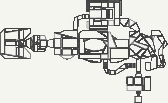
Recursion level 2 (only for the right subspace)
As a result, the SECTORS sectors were divided into convex subsectors (denoted as SSECTORS), and LINEDEFS were cut into segments (denoted as SEGS):
Work process in general
Here is the main rendering method (
R_RenderPlayerView ): void R_RenderPlayerView (player_t* player) { [..] R_RenderBSPNode (numnodes-1); R_DrawPlanes (); R_DrawMasked (); } Four operations are performed here:
R_RenderBSPNode: all subsectors on the map are sorted using the BSP tree. Large fragments are discarded using bounding boxes (shown in green in the previous image).R_RenderBSPNode: visible SEGS segments are projected onto the screen through a lookup table and truncated using a clipping array. Walls are drawn as columns of pixels. The size of the column is determined by the distance from the point of view of the player, the position of the Y column through height is associated with the player. The bases and the tops of the walls create planes visplanes. These structures are used for floor and ceiling rendering (they are called in flats code).R_DrawPlanes: Planes visplanes are converted from columns of pixels to rows of pixels and rendered on the screen.R_DrawMasked:R_DrawMasked“objects” (enemies, objects, and transparent walls).
Sort binary space decomposition
Two examples with E1M1 (the first Doom card) and BSP are as follows:
// // ax + by + c = 0 // = (a,b) // ( A B): normal = (-1,0) c = 3500 // A ( A A1 A2): normal = (1,0) c = -2500 // B ( B B1 B2): normal = (-0.24,0.94) c = -650 // (x,y) // . 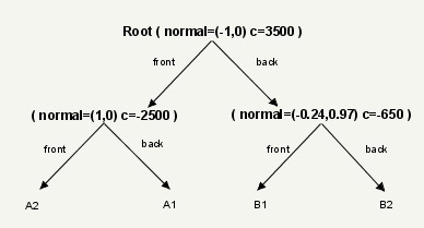
Traversing a BSP tree always starts at the root node and sorts both subspaces. Recursion is performed for both child nodes.
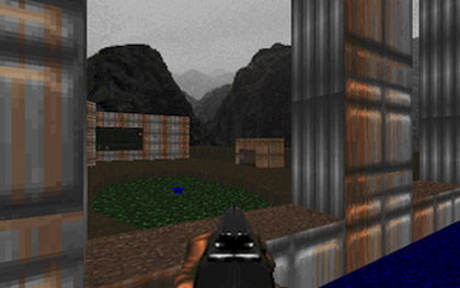
Example 1: The player (green dot) looks through the window from the point p = (2300,1900):
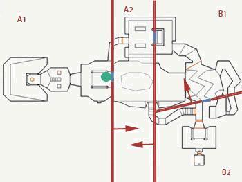
// = ( 2300, 1900 ) // R_RenderBSPNode AB (-x + 3500 = 0): -2300 + 3500 = 1200 , , . (A , B). // R_RenderBSPNode : A1/A2 B1/B2. // R_RenderBSPNode A1/A2 (x - 2500 = 0): 2300 - 2500 = -200 , . (A1 , A2). // R_RenderBSPNode B1/B2 (-0.24x +0.97y - 650 = 0): -0.24 * 2300 + 0.97 * 1900- 650 = 641 , . (B1 , B2). : : { A1, A2, B1, B2 } Example 2: The player (green dot) looks from the secret balcony at the point p = (5040, 2400):

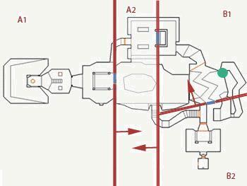
// = ( 5040, 2400 ) // R_RenderBSPNode AB (-x + 3500 = 0): -5040 + 3500 = -1540 , . (B , A). // R_RenderBSPNode : A1/A2 B1/B2. // R_RenderBSPNode B1/B2 (-0.24x +0.97y - 650 = 0): -0.24 * 5040 + 0.97 * 2400 - 650 = 468 , . (B1 , B2). // R_RenderBSPNode A1/A2 (x - 2500 = 0): 5040 - 2500 = 2540 , . (A2 , A1). : : { B1, B2, A2, A1 } BSP trees allowed SEGS to be sorted from any point on the map at a constant speed, regardless of the player’s position. The price for this was one multiplication and one summation for each plane. In addition, due to the testing of the bounding boxes, large parts of the map are discarded.
Note: Not immediately obvious, but BSP sorts all the SEGS segments around the player, even those that he does not look at. When using BSP, it is necessary to apply the cut-off by the pyramid of visibility
Walls
When sorting BSP walls (SEGS) from near to far, only the nearest 256 walls are rendered. The two vertices of each SEGS are converted into two corners (relative to the player’s position).
Note: In 1993, only the most powerful 486DX machines had an FPU (floating point coprocessor), so the Doom slider computed all angles using a binary angle measurement (Binary Angular Measurement, BAM) that only worked with
int numbers, the float format was rarely used . For the same reason, accuracy exceeding the accuracy of integers was achieved using fixed_t , a binary format of 16.16 with a fixed comma (for more information, read here and here ).After converting the X-coordinates of the screen space to the corners, they were obtained using lookup tables (
viewangletox ). Since BAM was executed in int , the corners were first scaled from 32 to 13 bits using a 19-bit offset to the right to fit into an 8KB lookup table.Then the walls were trimmed according to the clipping array (
solidsegs . Some articles on the Doom engine mention a linked list, but it doesn't look like it was used). After trimming, the remaining space was interpolated and drawn as pixel columns: the height and Y coordinate of the pixel column were based on the SEGS sector height and the distance from the player's point of view, respectively.Note on clipping surfaces: Clipping of invisible surfaces was done using
angle2-angle1 > 180 . Only the walls in the visible area were rendered.
Note: Not all walls consist of a single texture. The walls could have a lower texture, an upper texture, and a medium texture (which could be transparent or translucent). As seen in the video below, it was convenient for simulating windows: the “window” is actually a sector with high floors and a missing average texture.
Interesting fact: Since the walls were rendered as vertical columns, the textures of the walls were kept in memory rotated 90 degrees to the left. This trick allowed for full use of the CPU's pre-caching feature: the process of reading a texel wall from RAM also pre-filled the CPU cache with eight adjacent texels on each side. Since the subsequent read data was already in the RAM cache, a significant decrease in read latency was achieved. You can read more about pre-caching and aligning data in memory in the book The Art of Assembly Language Programming (Section 3.2.4 Cache Memory).
Flat surfaces (floor and ceiling), or the infamous visplanes
When drawing the columns of the walls, the upper and lower coordinates of the screen space were used to generate “visplanes”, areas in the screen space (not necessarily continuous horizontally). This is how visplane_t is declared in the Doom engine.
// // visplane? // typedef struct { fixed_t height; int picnum; int lightlevel; int minx; int maxx; byte top[SCREENWIDTH]; byte bottom[SCREENWIDTH]; } visplane_t; The first part of the structure stores information about the “material”, (
height, picnum, lightlevel ). The last four members define the covered area of the screen space.If two subsectors have the same material (height, texture and illumination level), the Doom engine tried to merge them together, but due to the visplante_t structure limitations this was not always possible.
For the entire width of the screen, visplane can store a pixel column location (since visplanes are obtained by projecting walls onto the screen, they are created as columns of pixels).
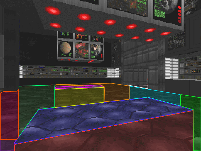
Here are the three main visplanes of the home screen:
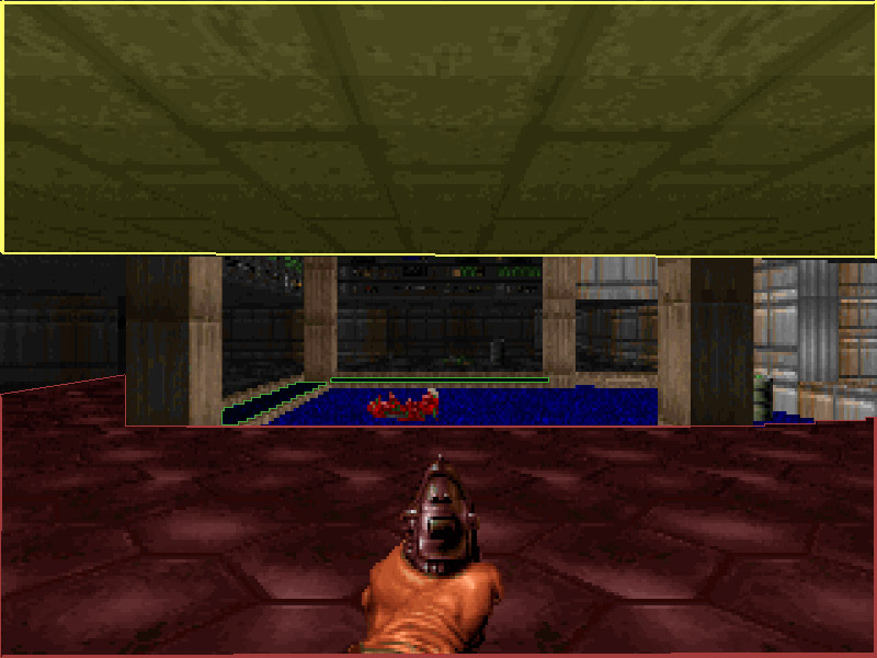
The green plane is particularly interesting: it demonstrates that
visplane_t can store discontinuous (but only in the horizontal direction) areas. Since the column is continuous, the visplane can store it. This limitation manifests itself in the engine: some subsectors can be merged and rendered using one visplane, but if there is something vertically between them, then merging is impossible.Here is a screenshot and a corresponding video showing the visplane fragmentation.
Interesting fact: The hard-coded visplanes limit (
MAXVISPLANES 128) was a big headache for modders, because the game was falling out and returning to DOS. There may be two problems:"R_FindPlane: no more visplanes": The total number of different visplanes materials (height, texture and light level) is greater than 128.R_DrawPlanes: visplane overflow (%i): the number of visplanes fragmented exceeded 128.
Why limit the number to 128? Two stages of the rendering pipeline required performing a search on the visplanes list (using
R_FindPlane ). The search was linear, and perhaps for numbers greater than 128 turned out to be too expensive. Lee Killough later extended this limit, replacing the linear search with a hash-chain implementation.Objects and transparent walls
After all solid walls and walls with a “transparent medium texture”, as well as the surfaces of ceilings and floors are rendered, only “objects” remain: enemies, barrels, ammunition and translucent walls. They are rendered from the farthest to the nearest ones, but they are not projected into the screen space using the wall lookup table. The rendering process is performed by computing 16.16 binary numbers with a fixed decimal point.
Note: This video shows one of the worst-case scenarios when some pixels have to be redrawn three times.
Profiling
Downloading Chocolate Doom to Instruments on Mac OS X allowed doing some profiling:
It seems that the port [on the iPhone] rather accurately corresponds to the “vanilla” Doom: most of the time, the walls (
R_DrawColumn ), the ceiling / floor ( R_DrawSpan ) and the objects ( R_DrawMaskedColumn ) are R_DrawMaskedColumn . In addition to drawing, I noticed high resource costs for interpolating walls ( R_RenderSegLoop ) and converting the visplane from columns to rows of pixels ( R_MakeSpans ). Then, finally, it comes to AI ( R_MobjThinker ) and the BSP tree R_RenderBSPNode ( R_RenderBSPNode ).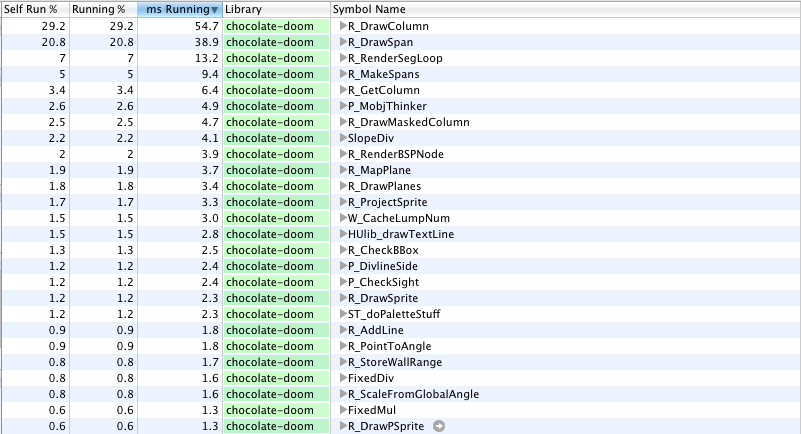
With the help of the inverted call tree, you can see that most of the work really consists in traversing the BSP tree, rendering the walls and generating visplanes:
R_RenderBSPNode (the second column is the percentage of time spent).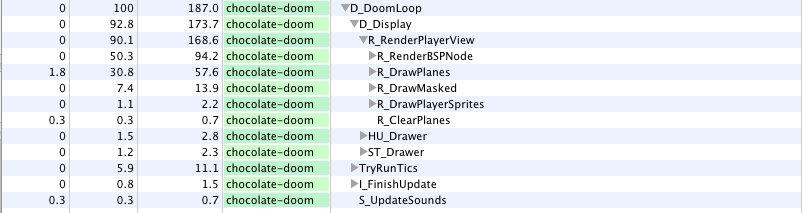
Together
And finally, a video of generating the legendary first screen in which you can see in order:
- Walls as rows of pixels, from near to far
- Flat surfaces as rows of pixels, from near to far
- Items from far to near.
Interesting Facts
- Since Doom was developed on the NeXTSTEP system with a linear virtual memory model, id Software decided to abandon the EMS and XMS that were used in most games of that time. Instead, developers used DOS / 4G, a memory expander that allowed software to access RAM in protected mode in a real-mode operating system (DOS).
- The NexT workstation was so powerful that it was able to run the editor, the game, and the debugger at the same time. When the game was fairly stable, the code was sent over the network to a PC, where it was compiled under DOS / x86 by the Watcom compiler. Thanks to DOS / 4G, the code was executed in the same memory model on both the PC and NeXT.
- An interesting video that complements the book "Masters of Doom":
- Many details can be explored on the sites of John Romero (John Romero) rome.ro and planetromero.com .
Recommended reading
- The original source code , released in 1997, is easy to read, but there are few or no comments, it does not compile, there is no source code for the audio subsystem (due to licensing issues).
- Chocolate Doom : Oh, yes! This is just a terrific port, it is based on SDL and compiles with brio on almost any platform. This is the port I hacked to generate a video for the article.
- The book "Graphics Programming Black Book" by Michael Abrash. It helps to understand BSP-trees and is a great source of inspiration. This guy might even make you fall for an assembler.
- Masters of Doom : the history of id Software with many details about creating Doom
Source: https://habr.com/ru/post/322598/
All Articles