Bridge-domains and virtual-switch in JunOS

Somewhere a year ago or earlier I wrote an article on routing-instance in JunOS, where I described the main types of routing instances, with the exception of virtual switch and evpn. You can read about the latter in an article on EVPN, but virtual-switch has so far been ignored. Many people underestimate the possibilities of this routing instance - and after all the functionality is decent. In this small article we will look at what virtual-switch is, what it is eaten with and whether you need it.
Before going directly to the discussion and configuration of a virtual switch, we need to highlight two very important issues:
1. Method (style) of configuring a tagged interface in JunOS;
2. What is a bridge-domain.
JunOS provides us with two methods for configuring a tagged interface for use in a bridge domain:
')
1. Service Provider
2. Enterprise
Let us dwell on them in more detail.
Note: all examples use flexible-ethernet-services encapsulation and flexible-vlan-tagging tagging, which gives maximum freedom in configuring interfaces:bormoglotx@RZN-PE1> show configuration interfaces ae3 apply-groups-except CORE; description "to RZN-CE1 | ae0"; flexible-vlan-tagging; encapsulation flexible-ethernet-services; aggregated-ether-options { minimum-links 1; link-speed 1g; lacp { active; periodic fast;
Service Provider.
This method of configuring the interface gives us complete freedom to manipulate the vlan tags, for which we use the pop (remove), push (add), swap (replace) tag, and two tag operations, for example pop-swap, to remove the top tag and replacing the bottom when using double tagging. The easiest way to use this method of creating a tagged interface is as follows:
[edit] bormoglotx@RZN-PE1# show interfaces ae3.10 encapsulation vlan-bridge; vlan-id 10; This is a simple tagged interface that allows only 10 vlan. When adding interfaces configured by this method to the bridge-domain, you must explicitly specify this interface in the configuration of the bridge-domain itself:
[edit] bormoglotx@RZN-PE1# show bridge-domains BRIDGE-10 domain-type bridge; vlan-id 10; interface ae3.10; You can use vlan-maps to manipulate vlan tags: input-vlan-map and output-vlan-map. For example, let's rewrite tag 10 to tag 20:
[edit] bormoglotx@RZN-PE1# show interfaces ae3.10 encapsulation vlan-bridge; vlan-id 10; input-vlan-map { swap; vlan-id 20; } output-vlan-map swap; When using a vlan-map, do not forget to add a reverse action — that is, if you specify only input-vlan-map and forget about output-vlan-map, you will receive that the tag will correspond to the reception, but not to the transmission.
Note: when using interfaces configured in bridge provider's domains configured in Service Provider with tag rewriting, you cannot specify vlan-id, you will get an error:[edit] bormoglotx@RZN-PE1# show bridge-domains BRIDGE-10 { domain-type bridge; vlan-id 10; ## ## Warning: interface with input/output vlan-maps cannot be added to a routing-instance with a vlan-id/vlan-tags configured ## interface ae3.10;
If you decide to use a vlan-map, you will have to remove the vlan-id from the bridge-domain and manage the tag numbers on each interface that belong to this bridge-domain manually. But there is also a simpler way of rewriting tags, which we will look at later.
Enterprise:
This method is much simpler than the previous one. When configuring the interface, we indicate that it is a trunked or aks interface. Based on this, we can specify several tags (if the interface is trunked) or one (if the interface is an interface). But for simplicity you have to pay for example with the following drawbacks - there is no possibility to overwrite the internal tag with QinQ - you can access only the external tag or, for example, manually rewrite the tag if it does not match the vlan-id in the bridge-domain, unlike the Service Provider model . The configuration looks like this:
[edit] bormoglotx@RZN-PE1# show interfaces ae0.10 encapsulation vlan-bridge; family bridge { interface-mode trunk; vlan-id-list 10; } In the list of vlans, the vlan-id-list can contain more than one number of the vlan - up to 4094. This interface should not be added to the bridge-domain - it will be added to it automatically if the number of the vlan in the bridge-domain and on the configured interface matches. For example, the configuration of a bridge-domain with vlan-id 10:
bormoglotx@RZN-PE1> show configuration bridge-domains BRIDGE-10 domain-type bridge; vlan-id 10; interface ae3.10; The ae0.10 court interface has not been added (if you try to do this, JunOS will give you an error). And now let's see the state of our bridge-domain:
bormoglotx@RZN-PE1> show bridge domain BRIDGE-10 Routing instance Bridge domain VLAN ID Interfaces default-switch BRIDGE-10 10 ae0.10 ae3.10 The interface was automatically added to the bridge-domain, because its vlan number is equal to the configured vlan-id in the BRIDGE-10 bridge-domain. If there are several vlans in the vlan-id-list, the interface will also be added to several bridge-domains
This method of configuring the interface also allows you to manipulate vlan tags, although the configuration at first glance may seem somewhat confusing.
Let's do the same as with the interface ae3.10 - rewrite the tag from 10 to 20:
[edit] bormoglotx@RZN-PE1# show interfaces ae0.10 encapsulation vlan-bridge; family bridge { interface-mode trunk; vlan-id-list 20; vlan-rewrite { translate 10 20; } } Please note that the number of the vlan with which the package will arrive from the client is not indicated in the vlan-id-list (if specified, JunOS will generate an error). But the most important thing to remember is that now this is an interface with vlan-id 20 and not 10, and it will be added to the bridge-domain with vlan-id 20, not 10. If you have several vlans on one interface (this is still trunk interface), then you can write several translation rules - for each vlan separately. For those vlan, for which the translation rule is absent - the tag will remain the one with which it arrived from the client (of course, if this vlan is allowed on this interface).
Above, I showed that this interface was automatically attached to the bridge-domain BRIDGE-10 because their vlan numbers matched. Let's check now whether the interface has remained in this bridge domain or has been moved:
bormoglotx@RZN-PE1> show bridge domain BRIDGE-10 Routing instance Bridge domain VLAN ID Interfaces default-switch BRIDGE-10 10 ae3.10 The interface has been removed from the BRIDGE-10 bridge-domain, as they now do not have vlan numbers. Let's change the number of the vlan in this bridge-domain to 20 and check again whether ae0.10 will be added now:
bormoglotx@RZN-PE1> show bridge domain BRIDGE-10 Routing instance Bridge domain VLAN ID Interfaces default-switch BRIDGE-10 20 ae0.10 ae3.10 As it should be, the interface got into this bridge-domain.
Note: we changed the number of the vlan in the bridge-domain itself, but here on ae3.10 the number of the vlan did not change, but it is still in the bridge-domain. This is normal and how it works, we will look at a little later.
Bridge-domain
Since we have dealt with the methods of configuring interfaces, we now proceed directly to the bridge-domains.
Bridge-domain is a set of logical interfaces that have the same characteristics of learning MAC addresses and flooding. Bridge-domain is a synonym for the word broadcast domain. For example, imagine that we created a bridge-domain consisting of 3 interfaces. When receiving a broadcast frame, the router will flood it to all interfaces, except for the one from which this frame is received (as you understand this is the split-horizon function), that is, in our case, if the packet is received from interface A, it will be sent to interface B and C. The router will not send the packet anywhere else, which ensures the isolation of one bridge-domain from another. As a result, we get the definition that is written at the beginning of this paragraph - the study of MAC addresses and flood is limited only by the set of interfaces that are attached to this bridge-domain. Under certain circumstances, the vlan will be synonymous with the bridge-domain, but this is the exception rather than the rule.
Let's create a simple bridge-domain - in fact we will throw in vlan 100 between RZN-PE1 and RZN-PE2, as shown in the diagram below:
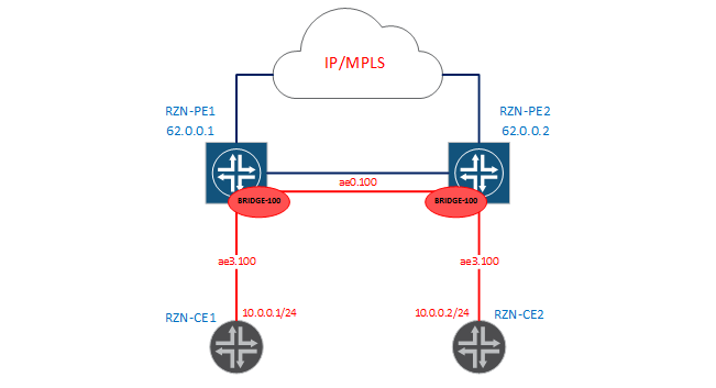
Since in this case the configuration of the bridge-domain on both PEs is identical, I will only give conclusions from the first box. To begin with, we’ll check that now we don’t have a connectivity between RZN-CE1 and RZN-CE2 in 100:
bormoglotx@RZN-CE1> show configuration interfaces ae0.100 vlan-id 100; family inet { address 10.0.0.1/24; } bormoglotx@RZN-CE1> ping rapid routing-instance VR1 source 10.0.0.1 10.0.0.2 PING 10.0.0.2 (10.0.0.2): 56 data bytes ..... --- 10.0.0.2 ping statistics --- 5 packets transmitted, 0 packets received, 100% packet loss Now let's switch to RZN-PE1 and add the interfaces we need and join them into the bridge-domain:
[edit] bormoglotx@RZN-PE1# show | compare [edit interfaces ae0] + unit 100 { + description "L2 for BRIDGE100"; + encapsulation vlan-bridge; + vlan-id 100; + } [edit interfaces ae3] + unit 100 { + description "to VR1"; + encapsulation vlan-bridge; + vlan-id 100; + } [edit] + bridge-domains { + BRIDGE-100 { + domain-type bridge; + vlan-id 100; + interface ae0.100; + interface ae3.100; + } + } As you remember, on the RZN-PE1 interface ae0 looks at its brother RZN-PE2, and ae3 towards RZN-CE1. A similar config is used on RZN-PE2. Now let's check the status of our bridge-domain:
bormoglotx@RZN-PE1> show bridge domain BRIDGE-100 detail Routing instance: default-switch Bridge domain: BRIDGE-100 State: Active Bridge VLAN ID: 100 Interfaces: ae0.100 ae3.100 Total MAC count: 0 Everything as we planned - in our domain there are two interfaces and the 100th number of the vlan. So far, no MAC addresses have been studied, since there has not yet been traffic exchange between RZN-CE1 / 2.
We correct this mistake by running a ping between the addresses we need:
bormoglotx@RZN-CE1> ping rapid routing-instance VR1 source 10.0.0.1 10.0.0.2 PING 10.0.0.2 (10.0.0.2): 56 data bytes !!!!! --- 10.0.0.2 ping statistics --- 5 packets transmitted, 5 packets received, 0% packet loss round-trip min/avg/max/stddev = 3.451/6.046/13.350/3.674 ms Now we can check whether the MAC appeared in the forwarding table:
bormoglotx@RZN-PE1> show bridge domain BRIDGE-100 detail | match mac Total MAC count: 2 bormoglotx@RZN-PE1> show bridge mac-table bridge-domain BRIDGE-100 MAC flags (S -static MAC, D -dynamic MAC, L -locally learned, C -Control MAC SE -Statistics enabled, NM -Non configured MAC, R -Remote PE MAC) Routing instance : default-switch Bridging domain : BRIDGE-100, VLAN : 100 MAC MAC Logical NH RTR address flags interface Index ID 00:05:86:71:1c:c0 D ae0.100 00:05:86:71:e5:c0 D ae3.100 Poppies are studied, there is connectivity - all we need is we did. I would like to say a few words that a similar result could be achieved with the help of L2CKT. But first, L2CKT is a completely different service using MPLS as a transport and not learning MAC addresses (essentially a pipe from port A to port B), and secondly, in L2CKT you cannot add a third interface (you will have to do VPLS), and most importantly, you will not be able to tie a routing interface (irb) to L2CKT and release hosts from your bridge-domain to an external network. For clarity, add an irb interface to our bridge-domain, as shown in the diagram:
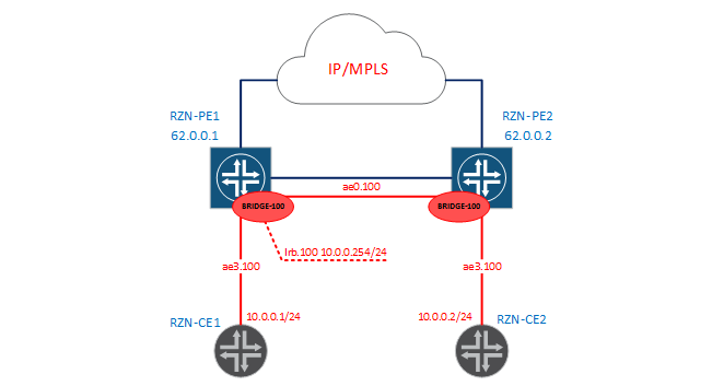
bormoglotx@RZN-PE1# show | compare [edit interfaces] + irb { + unit 100 { + description "L3 for BRIDGE-100"; + family inet { + address 10.0.0.254/24; + } + } + } [edit routing-instances] + VIRTUAL-ROUTER { + instance-type virtual-router; + interface irb.100; + } [edit bridge-domains BRIDGE-100] + routing-interface irb.100; Since inside the labs between the MX-themselves is also the network 10.0.0.0/24, I moved the irb interface to the virtual router. If the addressing did not overlap with us, then we could leave this interface in the GRT and thus release the hosts from our L2 domain to the outside world.
Note: The irb interface is not tagged, the unit number is set to 100 for ease of administration. When sending traffic to the routing interface, the vlan tag is removed from the packet, if present.
Note: The irb interface will be active only when it is added to the bridge-domain with at least one logical interface in the up state.
Note: Only one routing interface can be added to one bridge domain.
Now let's run ping for example from RZN-CE2 to 10.0.0.254 and check the performance of our configuration:
bormoglotx@RZN-CE2> ping routing-instance VR1 rapid source 10.0.0.2 10.0.0.254 PING 10.0.0.254 (10.0.0.254): 56 data bytes !!!!! --- 10.0.0.254 ping statistics --- 5 packets transmitted, 5 packets received, 0% packet loss round-trip min/avg/max/stddev = 3.385/19.526/79.125/29.821 ms Now let's complicate the task a little and collect the following scheme:
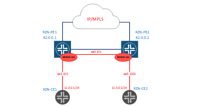
In the new scenario, we need to throw L2 between our REs again, but the problem is that 101 VLANs are terminated on RZN-PE1, but 1001 Vlan on RZN-PE2. When I wrote that under certain conditions a bridge-domain would be a synonym for the word vlan, I meant the case presented above (with the 100th vlan). The case considered now will prove to you that the bridge-domain is not always the same and the same. The first thing you probably thought was that you need to configure tag rewriting on some of the interfaces, for example, from 1001 to 101 on RZN-PE2. But now I’ll show you that JunOS will make it much easier for us. Add the following config to RZN-PE1:
[edit] bormoglotx@RZN-PE1# show | compare [edit interfaces ae0] + unit 101 { + encapsulation vlan-bridge; + vlan-id 101; + } [edit interfaces ae3] + unit 101 { + encapsulation vlan-bridge; + vlan-id 101; + } [edit bridge-domains] + BRIDGE-101 { + domain-type bridge; + vlan-id 101; + interface ae0.101; + interface ae3.101; + } As a result, the use of this config will appear on the RZN-PE1 bridge-domain BRIDGE-101:
bormoglotx@RZN-PE1> show bridge domain BRIDGE-101 Routing instance Bridge domain VLAN ID Interfaces default-switch BRIDGE-101 101 ae0.101 ae3.101 We now turn to the configuration from RZN-PE2:
[edit] bormoglotx@RZN-PE2# show | compare [edit interfaces ae0] + unit 101 { + encapsulation vlan-bridge; + vlan-id 101; + } [edit interfaces ae3] + unit 1001 { + encapsulation vlan-bridge; + vlan-id 1001; + } [edit bridge-domains] + BRIDGE-101 { + domain-type bridge; + vlan-id 101; + interface ae3.1001; + interface ae0.101; + } In the configuration, there are no rewriting of tags; if you look at the status of the bridge-domain, you can clearly see that the interface ae3.1001 is in the bridge-domain BRIDGE-101:
bormoglotx@RZN-PE2> show bridge domain BRIDGE-101 Routing instance Bridge domain VLAN ID Interfaces default-switch BRIDGE-101 101 ae0.101 ae3.1001 For good, since rewriting a tag is not configured at our place, it will not work. And let's check:
bormoglotx@RZN-CE1> ping rapid routing-instance VR1 source 11.0.0.1 11.0.0.2 PING 11.0.0.2 (11.0.0.2): 56 data bytes !!!!! --- 11.0.0.2 ping statistics --- 5 packets transmitted, 5 packets received, 0% packet loss round-trip min/avg/max/stddev = 5.033/7.733/13.904/3.206 ms Already interesting - there is connectivity, let's check the forwarding table for the presence of MAC addresses:
bormoglotx@RZN-PE2> show bridge mac-table bridge-domain BRIDGE-101 MAC flags (S -static MAC, D -dynamic MAC, L -locally learned, C -Control MAC SE -Statistics enabled, NM -Non configured MAC, R -Remote PE MAC) Routing instance : default-switch Bridging domain : BRIDGE-101, VLAN : 101 MAC MAC Logical NH RTR address flags interface Index ID 00:05:86:71:1c:c0 D ae3.1001 00:05:86:71:e5:c0 D ae0.101 With MAC in the forwarding table, everything is fine. But why did the connectivity between different vlans appear without configuring tag rewriting? The fact is that this is JunOS default behavior. Let's return to the configuration of the BRIDGE-101 bridge-domain itself on RZN-PE2:
bormoglotx@RZN-PE2> show configuration bridge-domains BRIDGE-101 domain-type bridge; vlan-id 101; interface ae3.1001; interface ae0.101; The thing is in the number of the vlan indicated by us: vlan-id 101. It works like this: for packets received in this bridge-domain with a tag that does not correspond to tag 101, JunOS automatically rewrites the tag. This is easy to see on the interface itself:
bormoglotx@RZN-PE2> show interfaces ae3.1001 Logical interface ae3.1001 (Index 339) (SNMP ifIndex 580) Flags: Up SNMP-Traps 0x20004000 VLAN-Tag [ 0x8100.1001 ] In(swap .101) Out(swap .1001) Encapsulation: VLAN-Bridge Statistics Packets pps Bytes bps Bundle: Input : 6 0 556 0 Output: 6 0 570 0 Adaptive Statistics: Adaptive Adjusts: 0 Adaptive Scans : 0 Adaptive Updates: 0 Protocol bridge, MTU: 1522 I draw your attention to the line with the following content:
VLAN-Tag [ 0x8100.1001 ] In(swap .101) Out(swap .1001) This line tells us what actions will be performed with the tag on reception from this interface (In (swap .101) - the tag changes to 101) and when transmitted to this interface (Out (swap .1001) - the tag changes to 1001) . For example, I will change the bridge-domain configuration:
[edit] bormoglotx@RZN-PE2# show bridge-domains BRIDGE-101 domain-type bridge; vlan-id none; interface ae3.1001; interface ae0.101; And again, let's see what will be done with the tag on ae3.1001:
bormoglotx@RZN-PE2> show interfaces ae3.1001 | match vlan-tag VLAN-Tag [ 0x8100.1001 ] In(pop) Out(push 0x0000.1001) Now the tag is removed for reception (rather than being rewritten), and tag 1001 is added to the transmission. But since the interface in the direction of RZN-PE1 is also tagged with us, in this case there will be manipulations with vlan numbers (only 101) :
bormoglotx@RZN-PE2> show interfaces ae0.101 | match vlan-tag VLAN-Tag [ 0x8100.101 ] In(pop) Out(push 0x0000.101) I think that some have figured out the bridge-domains. Let's now try to create another bridge-domain on RZN-PE1 with a tag of 100:
[edit] bormoglotx@RZN-PE1# show bridge-domains BRIDGE-100 { domain-type bridge; vlan-id 100; interface ae0.100; interface ae3.100; } BRIDGE-101 { domain-type bridge; vlan-id 101; interface ae0.101; interface ae3.101; } VLAN100 { vlan-id 100; } Check if the commit script will swear at the new configuration:
[edit] bormoglotx@RZN-PE1# commit check [edit bridge-domains] 'VLAN100' l2ald: Duplicate vlan-id exists for bridge domain BRIDGE-100 [edit bridge-domains] Failed to parse bridge domain hierarchy completely error: configuration check-out failed When we commit, we get an error - this vlan is already used in another bridge domain. How to be in this situation ?? Yes, you can put none and everything will fly, but this is not a solution to the problem, but a crutch (although all the transport is kept on crutches and gags, but you still want a more viable solution). There is a more elegant way - we just create another vlan space, which will be completely isolated from the existing one. This is what a virtual switch will help us with.
We will understand in more detail. We have 4094 vlan for one router. That is, in fact, you are limited in the creation of bridge-domains - a maximum of 4094 domains with a Vlan number. JunOS will not allow you to make two domains with the same vlan number. When I showed you the conclusion about the state of the bridge-domain, you probably noticed in this output the name of the routing-instance:
bormoglotx@RZN-PE1> show bridge domain BRIDGE-100 detail Routing instance: default-switch Bridge domain: BRIDGE-100 State: Active Bridge VLAN ID: 100 Interfaces: ae0.100 ae3.100 Total MAC count: 0 We are interested in this line Routing instance: default-switch. That is, even if you have not created any routing-instance with the type virtual-switch, then you will still have one such routing-instance, called default-switch. All bridge domains that I configured earlier were added to this instance. When you create a routing-instance of type virtual-switch, then you add another space from 4094 vlans that do not overlap in any way and do not affect already used vlan numbers. That is, making for example two virtual switches you make it possible within the same router to create three bridge-domains with the same vlan number, all of which bridge-domains will be completely isolated from each other. In addition, if your topology provides for backup paths that can lead to looping, the virtual switch allows you to run protocols of the stp family, although there is a restriction - you can add only the interface itself, not its units. And if you have two virtual switches to which you want to add the same interface but different units, JunOS will give you an error when adding the interface to stp. To use stp in this case you will have to use routing-instance layer2-control and mstp protocol.
But the possibilities of a virtual switch do not end there. In the previous cases of creating a bridge-domain, we used a direct link between RZN-PE1 and RZN-PE2, as a L2 link, and organized the connection with it. But this does not have a very good impact on fault tolerance, since the termination of this link will break our stretched L2 domain into two parts. To avoid this, you can use VPLS or EVPN, and we don’t have to do a separate routing-instance with vpls or evpn type - you can configure the VPLS / EVPN port in the virtual switch hierarchy and use it as a trunk port to organize L2 connectivity with remote PE. . Next, we will configure a virtual switch and will use VPLS exclusively for connectivity between PE routers.
Now we can proceed to the creation of a routing-instance with a virtual switch type. We will collect three schemes that will differ from each other and show the main possibilities of the bridge-domains.
1. Bridge-domain BRIDGE-2000
2. Bridge-domain BRIDGE-2001
3. Bridge domains BRIDGE-302 and BRIDGE-502
In the first scheme, we will use two vlans: 200 and 2000 (on the RZN-PE1 we will rewrite the tag 200 for 2000), in the second scheme, also two vlans: 201 and 2001 (but here we will use the Service Provider to configure the interface and not rewrite anything - JunOS it will do it for us), and in the third scheme we will use three vlans, manually rewrite the tags and configure different bridge-domains between RZN-PE1 and RZN-PE2 (one in the virtual switch, the second in the default switch).
BRIDGE-2000
Scheme of service is presented below.
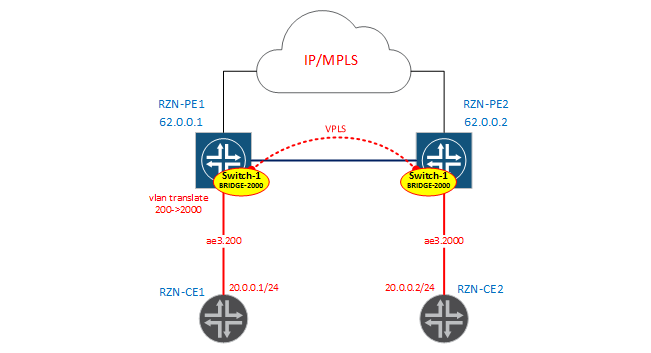
Configuring the interface on the RZN-PE1 side:
bormoglotx@RZN-PE1# show interfaces ae3.200 description "to VR2"; encapsulation vlan-bridge; family bridge { interface-mode trunk; vlan-id-list 2000; vlan-rewrite { translate 200 2000; } } As indicated in the diagram, we make tag rewriting from 200 to 2000. On the RZN-PE2 side, the interface configuration looks simpler:
[edit] bormoglotx@RZN-PE2# show interfaces ae3.2000 description "to VR2"; encapsulation vlan-bridge; family bridge { interface-mode trunk; vlan-id-list 2000; } Now let's move on to creating a virtual switch. The configuration will be approximately the same on RZN-PE1 and on RZN-PE2, therefore I will only give the config from the first RE:
bormoglotx@RZN-PE1> show configuration routing-instances vSwitch-1 instance-type virtual-switch; interface ae3.200; route-distinguisher 62.0.0.1:1; vrf-target { import target:1:1; export target:1:1; } protocols { vpls { site-range 2; no-tunnel-services; site SITE1 { site-identifier 1; } } } bridge-domains { BRIDGE-2000 { vlan-id 2000; } } Note: RD and RT values are present in the configuration of the routing-instance. This is not a required attribute of this routing-instance, but I used vpls Kompella, so I need RD / RT for the VPLS to work. If you use, for example, Martini without auto-discovery, then you do not need to specify RT / RD.
Now check the status of the bridge-domain BRIDGE-2000:
bormoglotx@RZN-PE1> show bridge domain instance vSwitch-1 BRIDGE-2000 Routing instance Bridge domain VLAN ID Interfaces vSwitch-1 BRIDGE-2000 2000 ae3.200 lsi.1048832 Besides the fact that the ae3.200 interface was automatically added to the bridge-domain, the lsi interface, which is our vpls port, was also added here:
Instance: vSwitch-1 Local site: SITE1 (1) connection-site Type St Time last up # Up trans 2 rmt Up Feb 23 12:20:38 2017 1 Remote PE: 62.0.0.2, Negotiated control-word: No Incoming label: 262146, Outgoing label: 262145 Local interface: lsi.1048832, Status: Up, Encapsulation: VPLS Description: Intf - vpls vSwitch-1 local site 1 remote site 2 Now RZN-PE2 in this bridge-domain is available to us through the VPLS port, and not as it was earlier through a direct link. Check whether there is connectivity between our hosts and how things are with the forwarding table:
bormoglotx@RZN-CE1> ping rapid routing-instance VR2 source 20.0.0.1 20.0.0.2 PING 20.0.0.2 (20.0.0.2): 56 data bytes !!!!! --- 20.0.0.2 ping statistics --- 5 packets transmitted, 5 packets received, 0% packet loss round-trip min/avg/max/stddev = 4.571/11.609/37.058/12.731 ms bormoglotx@RZN-PE1> show bridge mac-table instance vSwitch-1 vlan-id 2000 MAC flags (S -static MAC, D -dynamic MAC, L -locally learned, C -Control MAC SE -Statistics enabled, NM -Non configured MAC, R -Remote PE MAC) Routing instance : vSwitch-1 Bridging domain : BRIDGE-2000, VLAN : 2000 MAC MAC Logical NH RTR address flags interface Index ID 00:05:86:71:1c:c0 D lsi.1048832 00:05:86:71:e5:c0 D ae3.200 Everything is in order - the scheme works. Please note that, as in the default switch, no interfaces have been added to the bridge-domain itself — JunOS will automatically add them when the configuration is parsed (since we used the Enterprise configuration style). Our business in this scenario is to correctly specify which interfaces belong to the virtual switch and to correctly indicate the vlan-id in the bridge-domain (well, or vlan-id-range).
BRIDGE-2001
Now we will assemble the scheme for vlan 201 and 2001.
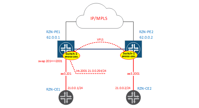
I will not make another virtual switch - I just add one more bridge-domain in vSwitch-1. As I said, we will use the Service Provider style in configuring interfaces without rewriting tags.
Note: within the virtual switch, as well as within the bridge-domain, no one forbids you to use interfaces configured using different methods - as it is easier for you - do so, the main thing then is not to get confused in the configuration yourself.
Interface configurations look very simple. On RZN-PE1:
[edit] bormoglotx@RZN-PE1# show interfaces ae3.201 description "to VR2"; encapsulation vlan-bridge; vlan-id 201; Counter-interface on the RZN-PE2 side:
[edit] bormoglotx@RZN-PE2# show interfaces ae3.2001 description "to VR2"; encapsulation vlan-bridge; vlan-id 2001; Now we add interfaces to our virtual switch:
[edit] bormoglotx@RZN-PE2# show routing-instances vSwitch-1 instance-type virtual-switch; interface ae3.2000; ## ## Warning: Only interface with 'interface-mode' is allowed in a virtual-switch ## interface ae3.2001; Got an error. The fact is that a virtual switch can be added to the interface hierarchy (now and then the hierarchy [edit routing-instances vSwitch-1 interface]) can only add interfaces in trunk or accessory mode, that is, the interface must be configured in Enterprise style. This is another difference between these two methods of configuring interfaces. If our interface is configured in the Enterprise style, then we cannot specify the bridge-domain in the hierarchy - the interface will be added to the bridge-domain by the vlan number. Therefore, when configuring a virtual switch, we need to add all our interfaces to it, which are in trunk or access mode - then JunOS will automatically add them to the required bridge-domain. But the interfaces configured in the Service Provider style must be specified in the bridge-domain manually. Therefore,when configuring a virtual switch, such interfaces are not necessary to add to the virtual switch in the interface hierarchy - we immediately add them to the bridge-domain we need, after which the interface will automatically be tied to the virtual switch that contains this bridge-domain.
[edit] bormoglotx@RZN-PE2# show routing-instances vSwitch-1 instance-type virtual-switch; interface ae3.2000; route-distinguisher 62.0.0.2:1; vrf-target { import target:1:1; export target:1:1; } protocols { vpls { site-range 2; no-tunnel-services; site SITE2 { site-identifier 2; } } } bridge-domains { BRIDGE-2000 { vlan-id 2000; } BRIDGE-2001 { vlan-id 2001; interface ae3.2001; } } Note: VPLS or EVPN port is a trunk port and passes all vlans and will be added to all bridge domains automatically.
The configuration on RZN-PE1 is similar to RZN-PE2 (only another interface has been added to the bridge-domain), so I will not show it. Check the state of the bridge-domains on both PE-kah:
bormoglotx@RZN-PE1> show bridge domain instance vSwitch-1 BRIDGE-2001 detail Routing instance: vSwitch-1 Bridge domain: BRIDGE-2001 State: Active Bridge VLAN ID: 2001 Interfaces: ae3.201 lsi.1048832 Total MAC count: 0 bormoglotx@RZN-PE2> show bridge domain instance vSwitch-1 BRIDGE-2001 detail Routing instance: vSwitch-1 Bridge domain: BRIDGE-2001 State: Active Bridge VLAN ID: 2001 Interfaces: ae3.2001 lsi.1048832 Total MAC count: 0 Check that tags are being overwritten on ae3.201:
bormoglotx@RZN-PE1> show interfaces ae3.201 | match vlan-tag VLAN-Tag [ 0x8100.201 ] In(swap .2001) Out(swap .201) And for verification, we will launch a ping between our hosts and check the forwarding table:
bormoglotx@RZN-CE1> ping rapid routing-instance VR2 source 21.0.0.1 21.0.0.2 PING 21.0.0.2 (21.0.0.2): 56 data bytes !!!!! --- 21.0.0.2 ping statistics --- 5 packets transmitted, 5 packets received, 0% packet loss round-trip min/avg/max/stddev = 7.026/9.563/15.398/3.000 ms bormoglotx@RZN-PE1> show bridge mac-table instance vSwitch-1 vlan-id 2001 MAC flags (S -static MAC, D -dynamic MAC, L -locally learned, C -Control MAC SE -Statistics enabled, NM -Non configured MAC, R -Remote PE MAC) Routing instance : vSwitch-1 Bridging domain : BRIDGE-2001, VLAN : 2001 MAC MAC Logical NH RTR address flags interface Index ID 00:05:86:71:1c:c0 D lsi.1048832 00:05:86:71:e5:c0 D ae3.201 Well, for completeness, we’ll add a routing interface to our virtual switch:
[edit] bormoglotx@RZN-PE1# show | compare [edit interfaces irb] + unit 2001 { + description "L3 for BRIDGE-2001 | vSwitch-1"; + family inet { + address 21.0.0.254/24; + } + } [edit routing-instances vSwitch-1 bridge-domains BRIDGE-2001] + routing-interface irb.2001; Note: the routing interface is added immediately to the virtual switch bridge domain we need, this interface should not be added to the virtual switch interface hierarchy.
Now check the availability of the irb interface with the RZN-CE2:
bormoglotx@RZN-CE2> ping routing-instance VR2 rapid source 21.0.0.2 21.0.0.254 PING 21.0.0.254 (21.0.0.254): 56 data bytes !!!!! --- 21.0.0.254 ping statistics --- 5 packets transmitted, 5 packets received, 0% packet loss round-trip min/avg/max/stddev = 3.369/10.704/36.307/12.813 ms There is connectivity, and in the forwarding table on RZN-PE2, the MAC address of the irb interface appeared, which is logically visible through the VPLS port:
bormoglotx@RZN-PE2> show bridge mac-table instance vSwitch-1 MAC flags (S -static MAC, D -dynamic MAC, L -locally learned, C -Control MAC SE -Statistics enabled, NM -Non configured MAC, R -Remote PE MAC) Routing instance : vSwitch-1 Bridging domain : BRIDGE-2001, VLAN : 2001 MAC MAC Logical NH RTR address flags interface Index ID 00:05:86:71:17:c0 D ae3.2001 00:05:86:71:26:c0 D lsi.1048576 00:05:86:71:8d:f0 D lsi.1048576 For reference, here is the irb MAC address of the interface with RZN-PE1:
bormoglotx@RZN-PE1> show interfaces irb | match current Current address: 00:05:86:71:8d:f0, Hardware address: 00:05:86:71:8d:f0 BRIDGE-302 >>> BRIDGE-502
Finally, let's collect a scheme in which we will manually rewrite tags:
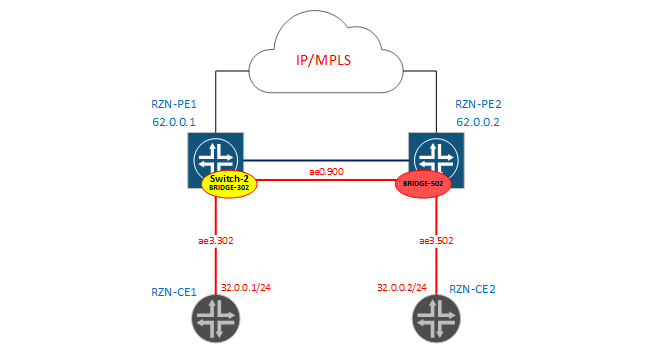
From the RZN-PE1 side, we have the bridge-domain DOMAIN-302, which is located in the virtual switch vSwitch-2:
[edit] bormoglotx@RZN-PE1# show | compare [edit interfaces ae0] + unit 900 { + encapsulation vlan-bridge; + vlan-id 900; + input-vlan-map pop; + output-vlan-map push; + } [edit interfaces ae3] + unit 302 { + encapsulation vlan-bridge; + vlan-id 302; + input-vlan-map pop; + output-vlan-map push; + } [edit routing-instances] + vSwitch-2 { + instance-type virtual-switch; + bridge-domains { + DOMAIN-302 { + interface ae3.302; + interface ae0.900; + } + } + } From the configuration it can be seen that at the reception the tag will be removed, and, which is logical, the transfer - tagging - nothing complicated.
From the RZN-PE2 side, we will simply have the bridge-domain BRIDGE-502 without creating a virtual switch (that is, it will be in the default switch):
bormoglotx@RZN-PE2# show | compare [edit interfaces ae0] + unit 900 { + encapsulation vlan-bridge; + vlan-id 900; + input-vlan-map pop; + output-vlan-map push; + } [edit interfaces ae3] + unit 502 { + encapsulation vlan-bridge; + vlan-id 502; + input-vlan-map pop; + output-vlan-map push; + } [edit bridge-domains] + BRIDGE-502 { + domain-type bridge; + interface ae3.502; + interface ae0.900; + } Naturally, and here we take off at the reception, and hang when sending vlan tags.
Ultimately, our bridge domains on PE1 / 2 have the following state:
bormoglotx@RZN-PE1> show bridge domain instance vSwitch-2 Routing instance Bridge domain VLAN ID Interfaces vSwitch-2 DOMAIN-302 NA ae0.900 ae3.302 bormoglotx@RZN-PE2> show bridge domain BRIDGE-502 Routing instance Bridge domain VLAN ID Interfaces default-switch BRIDGE-502 NA ae0.900 ae3.502 Instead of vlan-id, we have NA - since I have not defined the vlan-id, since I manually pass tags on the interfaces and cannot set this value. For example, information about the work of manipulating vlan tags with RZN-PE1:
bormoglotx@RZN-PE1> show interfaces ae3.302 | match vlan-tag VLAN-Tag [ 0x8100.302 ] In(pop) Out(push 0x0000.302) bormoglotx@RZN-PE1> show interfaces ae0.900 | match vlan-tag VLAN-Tag [ 0x8100.900 ] In(pop) Out(push 0x0000.900) Now we’ll run the ping between the hosts and check if we have connectivity:
bormoglotx@RZN-CE1> ping routing-instance VR3 source 32.0.0.1 32.0.0.2 rapid PING 32.0.0.2 (32.0.0.2): 56 data bytes !!!!! --- 32.0.0.2 ping statistics --- 5 packets transmitted, 5 packets received, 0% packet loss round-trip min/avg/max/stddev = 5.982/6.443/7.162/0.432 ms MAC addresses appear in the forwarding tables:
bormoglotx@RZN-PE1> show bridge mac-table instance vSwitch-2 MAC flags (S -static MAC, D -dynamic MAC, L -locally learned, C -Control MAC SE -Statistics enabled, NM -Non configured MAC, R -Remote PE MAC) Routing instance : vSwitch-2 Bridging domain : DOMAIN-302, VLAN : NA MAC MAC Logical NH RTR address flags interface Index ID 00:05:86:71:56:c0 D ae3.302 00:05:86:71:ed:c0 D ae0.900 The truth is, in such a bridge-domain (without specifying a vlan-id) there is a very important limitation - you cannot add a routing interface to this bridge-domain. If you try to do this, you will get an error:
[edit] bormoglotx@RZN-PE1# commit [edit routing-instances vSwitch-2 bridge-domains DOMAIN-302 routing-interface] 'routing-interface irb.302' routing-interface can be configured only under bridge-domain with 'vlan-id' or 'vlan-tags' error: commit failed: (statements constraint check failed) This can be a very big problem if the L2 domain grows large and suddenly you need to release it to the outside world - in this case you will have to rewrite too much config. Therefore, it is not recommended to use the latest model, I collected it only to demonstrate the possibility of a bridge-domain in JunOS.
That's all that I wanted to tell. I tried to explain everything as simply as possible, I hope that everything is clear to the reader. If there are any additions / comments - write correct / add. Thanks for attention!
PS> The article did not touch on some important topics, such as several learning domains in the same bridge-domain (for an unprepared person, this would be a brain explosion), an indication of the range of vlans for the bridge-domain, and so on. These topics are well described in the book Juniper MX-Series-Trio (book in English) - if you are interested in this topic - then this book will be an excellent educational tool.
Source: https://habr.com/ru/post/322560/
All Articles