MIPSfpga and in-circuit debugging
Supplied as part of the MIPSfpga package, the documentation, software, and configuration files assume the use of Bus Bluster as a hardware debugger. The article contains instructions for using for this purpose virtually any USB-UART adapter built on an FTDI chip with support for MPSSE (FT232H, FT2232H, FT4232H, FT2232D). Briefly describes the integration of the Visual Studio Code development environment and the GNU GDB debugger.
All configuration files described in the article, as well as part of the documentation are available on github .
System elements
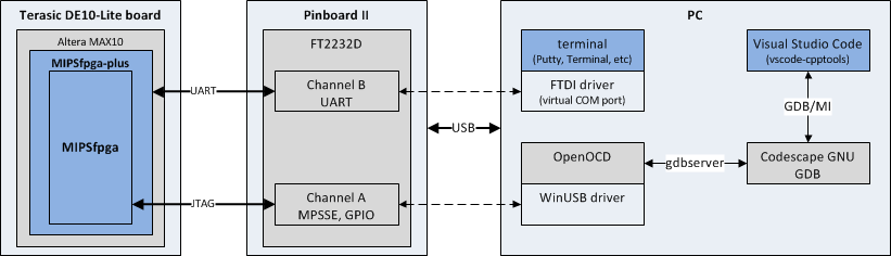
MIPSfpga is the industrial processor core of the MIPS microAptiv, the source codes of which are available under academic licenses [ L1 ]. MIPSfpga-plus is a system-on-a-chip design based on the MIPSfpga [ L2 ] core. In my case, the system is deployed on a Terasic DE10-Lite board with an Altera MAX10 FPGA on board [ L3 ].
The adapter (programmer, debugger) between the MIPSfpga-plus and PC is the Pinboard II [ L4 ] board with the FT22I [ D1 ] chip from FTDI [ L5 ]. Physically, the boards are interconnected by the UART and JTAG [ L6 ] interfaces. The first is used for console access to the system being debugged. The second is the basic debugging interface using EJTAG [ D7 ]. The difference between JTAG and EJTAG is very well shown in [ L7 ].
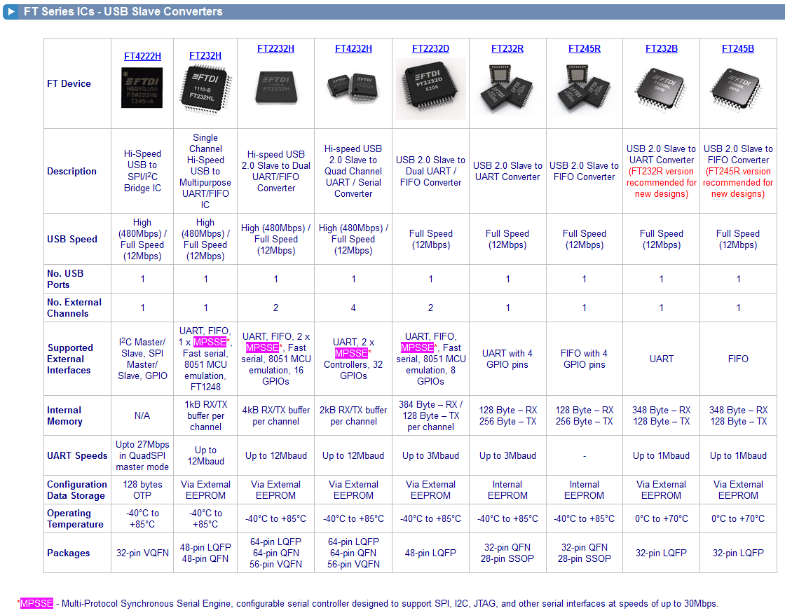
The key technology that greatly simplifies the construction of programmers and debuggers based on FTDI chips is the Multi-Protocol Synchronous Serial Engine (MPSSE) [ D2 , D3 , D4 ]. MPSSE support is a crucial point for the configuration described in the article. You can get similar results only on USB adapters based on the following FTDI chips: FT232H, FT2232H, FT4232H, FT2232D.
On the PC side, the interaction with the USB board is carried out: for the UART channel — using the usual FTDI drivers and any terminal program; for the MPSSE channel, the WinUSB driver is used (the work was done on a Windows-based system).
For compilation, the Codescape GNU Tools [ D9 ] is used, for debugging, the traditional bundle of OpenOCD [ L8 , D8 ] and GNU GDB [ D5 ]. These software packages are included with the Codescape MIPS SDK [ L12 ]. Their interaction with each other is carried out using the gdbserver [ L9 ] protocol.
Visual Studio Code (VSCode) [ L10 ] with the vscode-cpptools extension [ L11 ] installed is used as a GUI for debugging. Due to the fact that this extension is focused on high-level development (C / C ++), the interface lacks such views as viewing assembler instructions, viewing memory, direct access to registers.
Briefly about MPSSE and FTDI
MPSSE is a hardware-implemented set of primitive functions that greatly simplify the implementation of serial interfaces (SPI, I2C, JTAG). For example: send N bits on the clock edge, read M bits on the decay, set the X output to zero, etc.
Until 2014, Chinese on a substantial scale riveted counterfeit FTDI chips, for this reason USB-UART converters based on them were one of the most common on sites like ebay or aliexpress. And the developers were happy to build their solutions on them, to take at least the same support from OpenOCD. The list of USB adapter adapters manufactured by FTDI is shown below, with support for MPSSE - marked in color.
In 2014, FTDI releases updated drivers that refuse to work with counterfeit devices [ L13 , L14 ]. The number of offers for these USB-UART adapters has since declined somewhat, but they still remain one of the most common developers on hand.
Even FTDI, despite the excellent chips, sometimes blamed for the quality of software for them. Maybe it's my hands crooked, but Having suffered a lot from working with libMPSSE from under .NET, I wrote my analogue of this library in C # [ L15 ].
If any reader knows an adequate alternative for FTDI chips, an inexpensive and yet correctly supported OpenOCD, I will be grateful for the information.
USB module diagram
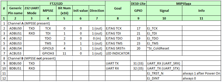
Below is a fragment of the Pinboard II debug board circuit, in your case the module circuit may be different. The main determining parameter for us is the ability to directly access the ports of the chip: one free MPSSE channel (for TCK, TDI, TDO, TMS) + 1 GPIO output for the reset signal (SRSTn) is enough for operation. For the second channel of the chip, the MPSSE functionality is not mandatory, and it is convenient to use it for UART interaction with the system being debugged.
The outputs of the FTDI chip are directly connected to the FPGA ports. Strictly speaking, this is a violation of [ D7 , D6 ], since it is assumed that there should be installed pull-up, pull-down or series-connected resistors. Everything works without them for me: carefully check the setting of the ports for input-output, check the maximum current limit on the FPGA ports involved for EJTAG.
The voltage at the terminals of the adapter is set to 3.3V. In the case of Pinboard II, a separate jumper (VCCIO_PWR_SEL) is provided for selecting this voltage. For other boards, be guided by their schemes and FPGA settings, in some cases it may be necessary to refine the adapter (which is simpler) and / or the level conversion circuit [ L16 ] (which is more difficult and can lead to interference or reduced speed).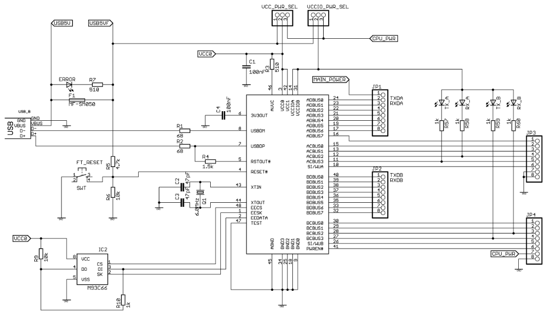
Typical EJTAG connection
A typical wiring diagram for the EJTAG interface is obtained from [ D6 ]. The optional DINT and TRSTn inputs are not used in this configuration. Compliance of the rest is given in the table.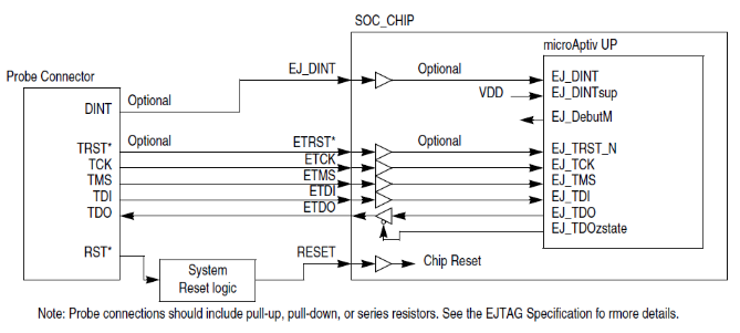
Table of connecting the USB module to the FPGA
Configuration files ( on github )
# # OpenOCD config for using FT2232D that is directly connected # to FPGA as MIPSfpga EJTAG debugger # Any FTDI USB IC with MPSSE support (required) can be used # # 2017, Stanislav Zhelnio # # ########################################################## # interface part # ########################################################## # interface, transport and channel setup # (use zadig to install WinUSB driver instead of FTDI one) interface ftdi transport select jtag ftdi_channel 0 ftdi_vid_pid 0x0403 0x6010 # ftdi MPSSE initial value and direction # for detailed description of Magic Numbers look at # connection table and FTDI AppNote AN_108: # chapter 2.1 Data bit Definition ftdi_layout_init 0x0018 0x081b # special signals # described in OpenOCD User's Guide: # chapter 8.2 Interface Drivers (ftdi) # chapter 9 Reset Configuration # nTRST is not used ftdi_layout_signal nSRST -data 0x0010 -oe 0x0020 ftdi_layout_signal LED -ndata 0x0800 -oe 0x0800 # speed setup # decrease when errors adapter_khz 10000 # ########################################################## # target part # ########################################################## # reset delays # described in OpenOCD User's Guide: # chapter 9 Reset Configuration adapter_nsrst_delay 100 jtag_ntrst_delay 100 # reset sygnal config # nSRST is directly connected to MIPSfpga (~SI_ColdReset) wire reset_config srst_only separate srst_nogate srst_push_pull # To check connection and scan EJTAG chain uncomment this # and comment all that is bellow then 'shutdown' command. # Use IDCODE value to detect connection errors: # IDCODE that was set in RTL config should be identical # to -expected-id result in 'shutdown' output. # The IDCODE structure is described in EJTAG Specification: # chapter 6.5.1 Device Identification (ID) Register #shutdown # tap connector and target creation # change -expected-id to your IDCODE value # for other arguments see at OpenOCD User's Guide jtag newtap auto0 tap -expected-id 0x000f1005 -irlen 5 -ircapture 0x1 -irmask 0x1f target create auto0.tap mips_mAptiv -endian little -chain-position auto0.tap # tap configuration # change params acording to compile and memory settings # for details see at OpenOCD User's Guide auto0.tap configure -work-area-phys 0xa0003ff00 -work-area-size 256 -work-area-backup 0 # EJTAG scan perion mips32 scan_delay 20000 # run the debugger process and wait for gdb connection init - the main and only configuration file for OpenOCD;
- conditionally, it can be divided into 2 parts: one describes the connection of the programmer and the target system (interface part), the second - the settings specific to the kernel being debugged (target part). Inside the OpenOCD catalog, they are usually placed in different folders, here - for simplicity, they are combined into one.
{ "configurations": [ { "name": "Mac", "includePath": [ "/usr/include", "/usr/local/include" ], "browse": { "limitSymbolsToIncludedHeaders": true, "databaseFilename": "" } }, { "name": "Linux", "includePath": [ "/usr/include", "/usr/local/include" ], "browse": { "limitSymbolsToIncludedHeaders": true, "databaseFilename": "" } }, { "name": "Win32", "includePath": [ "C:/Program Files (x86)/Microsoft Visual Studio 14.0/VC/include/*" ], "browse": { "limitSymbolsToIncludedHeaders": true, "databaseFilename": "" } }, { "name": "mips-mti-elf", "includePath": [ "D:/Codescape/Toolchains/mips-mti-elf/2016.05-03/lib/gcc/mips-mti-elf/4.9.2/include/*" ], "browse": { "limitSymbolsToIncludedHeaders": true, "databaseFilename": "" } } ] } - vscode-cpptools extension configuration file;
- contains information about the location of the header files, which is necessary to simplify navigation through the sources and the work of the completion function in the VSCode editor window.
{ "version": "0.2.0", "configurations": [ { "name": "MIPS Load", "type": "cppdbg", "request": "launch", "program": "${fileDirname}/program.elf", "cwd": "${fileDirname}", "miDebuggerPath": "d:/CODESC~1/TOOLCH~1/mips-mti-elf/2016.05-03/bin/mips-mti-elf-gdb.exe", "setupCommands": [ {"text": "file 'D:/mipsfpga-plus/programs/00_counter/program.elf'"}, {"text": "target remote localhost:3333"}, {"text": "set endian little"}, {"text": "monitor reset halt"}, {"text": "load"}, {"text": "br main"}, {"text": "monitor continue"} ], "customLaunchSetupCommands": [], "launchCompleteCommand": "None", "targetArchitecture": "mips" //Uncomment this to debug //,"logging": { "engineLogging": true } //or this for verbose debug //,"logging": { "engineLogging": true, "trace": true, "traceResponse": true } }, { "name": "MIPS Attach", "type": "cppdbg", "request": "launch", "program": "${fileDirname}/program.elf", "cwd": "${fileDirname}", "miDebuggerPath": "d:/CODESC~1/TOOLCH~1/mips-mti-elf/2015.06-05/bin/mips-mti-elf-gdb.exe", "setupCommands": [ {"text": "file 'D:/mipsfpga-plus/programs/00_counter/program.elf'"}, {"text": "target remote localhost:3333"}, {"text": "set endian little"} ], "customLaunchSetupCommands": [], "launchCompleteCommand": "None", "targetArchitecture": "mips" //Uncomment this to debug //,"logging": { "engineLogging": true } //or this for verbose debug //,"logging": { "engineLogging": true, "trace": true, "traceResponse": true } } ] } - VSCode configuration file containing the settings for running the program being debugged;
- in this case, describes two launch profiles: "MIPS Load" - load the firmware into the system's memory, then proceed to debugging; "MIPS Attach" - connect to the already-stitched system.
Primary setup
- connect the USB module to the PC;
- wait until the FTDI drivers are installed using the Zadig program, perform a driver change on the channel from MPSSE to WinUSB;
- copy the mipsfpga_ftdi.cfg configuration file to the directory with OpenOCD;
- In case your connection scheme differs for some reason from the one shown in the table, you need to recalculate the initialization parameters of OpenOCD, in particular, the arguments of the ftdi_layout_init and ftdi_layout_signal commands .
Consider the order in which they are received for the above connection table:
0x0018 - set 1 as the initial value on the ports ADBUS3 and ADBUS4 (bits 3 and 4, respectively);
0x081b - configure ports ADBUS0,1,3,4, ACBUS3 on the output (bits 0-3,4, 11).ftdi_layout_init 0x0018 0x081b- for the ftdi_layout_signal command , the logic is the same, the matching arguments of the -data and -oe (output enable) parameters mean that the connection is made directly, without any buffer. Using -ndata allows you to invert the output.
- pin assignment to specific bits is given in section 2.1 of the applet [ D3 ].
Settings on the MIPSFpga side
- When the EJTAG connection is initialized, the device being debugged sends the IDCODE register value to the PC, which is specified by the developer in the RTL code. I recommend to set any arbitrary (nonzero) values in this register, since this will help in determining connection errors: if the IDCODE received during connection does not match the one specified in the code, then an error has crept in somewhere.
- The format of this register [ D7 ] is as follows:
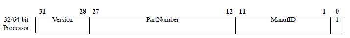
- The EJ_ManufID and EJ_PartNumber parameters are set in the mfp_system.v file;
- check and set the values of EJ_DINT and EJ_TRST_N. In the configuration in question, they are not used for connection:
assign EJ_DINT = 1'b0; assign EJ_TRST_N = 1'b1; Compilation settings
- make sure that the compiler settings in terms of memory usage do not contradict the parameters of the configure command in the mipsfpga_ftdi.cfg file;
- add debug symbols - -g -gdwarf-2 parameters
- set the optimization level to -O0 or -O1 . With -O2 debugging will also work, but the execution of the code may not be consistent: the pointer of the current executed line of code will "jump".
Connection test
- open the file mipsfpga_ftdi.cfg and comment out all the commands that go after setting the reset signal (after reset_config ). Uncomment the shutdown command . In this configuration, OpenOCD will connect to the device being debugged, receive IDCODE and disconnect;
- execute the openocd-0.9.2.exe command in the console -f mipsfpga_ftdi.cfg
the result of its correct execution is the following output, where 0x000f1005 is the previously defined IDCODE
Open On-Chip Debugger 0.9.1-dev-microAptiv-dirty (2015-05-08-15:32) Licensed under GNU GPL v2 For bug reports, read http://openocd.sourceforge.net/doc/doxygen/bugs.html adapter speed: 10000 kHz adapter_nsrst_delay: 100 jtag_ntrst_delay: 100 srst_only separate srst_nogate srst_push_pull connect_deassert_srst shutdown command invoked Info : clock speed 10000 kHz Warn : There are no enabled taps. AUTO PROBING MIGHT NOT WORK!! Warn : AUTO auto0.tap - use "jtag newtap auto0 tap -expected-id 0x000f1005 ..." Warn : AUTO auto0.tap - use "... -irlen 5" Warn : gdb services need one or more targets defined- check that exactly the value that was previously specified in the RTL code ( mfp_system.v ) was received ;
- in case the values diverge, it is necessary to find and fix the connection error. It is possible that you should slow down. In my case, for example, the probes of the connected logic analyzer made noise;
- after the correct IDCODE value is successfully received, the file can be returned to the initial state.
Debug in console mode
- run openocd-0.9.2.exe -f mipsfpga_ftdi.cfg . Sometimes, with a sudden loss of communication, OpenOCD may hang, so I prefer to run it in a separate terminal window.
The following output is correct, after which OpenOCD does not interrupt the operation and waits for a connection from gdb:
Open On-Chip Debugger 0.9.1-dev-microAptiv-dirty (2015-05-08-15:32) Licensed under GNU GPL v2 For bug reports, read http://openocd.sourceforge.net/doc/doxygen/bugs.html adapter speed: 10000 kHz adapter_nsrst_delay: 100 jtag_ntrst_delay: 100 srst_only separate srst_nogate srst_push_pull connect_deassert_srst scan delay: 20000 nsec running in fast queued mode Info : clock speed 10000 kHz Info : JTAG tap: auto0.tap tap/device found: 0x000f1005 (mfg: 0x002, part: 0x00f1, ver: 0x0)in a separate terminal window, run gdb: mips-mti-elf-gdb -q program.elf and perform several debugging operations
> mips-mti-elf-gdb -q program.elf Reading symbols from program.elf...done.connection to the system being debugged
(gdb) target remote localhost:3333 Remote debugging using localhost:3333 0xbfc00000 in ?? ()setting the target byte order
(gdb) set endian little The target is assumed to be little endiansystem shutdown
(gdb) monitor reset halt JTAG tap: auto0.tap tap/device found: 0x000f1005 (mfg: 0x002, part: 0x00f1, ver: 0x0) target state: reset entered debug state at PC 0xbfc00000, target->state: halted target state: halted target halted in MIPS32 mode due to debug-request, pc: 0xbfc00000firmware download
(gdb) load Loading section .text_ram, size 0x260 lma 0x80001000 Loading section .init, size 0x24 lma 0x80001260 Loading section .fini, size 0x1c lma 0x80001284 Loading section .eh_frame, size 0x4 lma 0x800012a0 Loading section .data, size 0xc lma 0x800012a4 Loading section .ctors, size 0x8 lma 0x800012b0 Loading section .dtors, size 0x8 lma 0x800012b8 Loading section .jcr, size 0x4 lma 0x800012c0 Loading section .reset, size 0x280 lma 0x9fc00000 Start address 0xbfc00000, load size 1348 Transfer rate: 12 KB/sec, 149 bytes/write.setting a breakpoint to enter the main function
(gdb) b main Breakpoint 1 at 0x800011e0: file main.c, line 14.code execution
(gdb) c Continuing. entered debug state at PC 0x800011e0, target->state: halted [Remote target] #1 stopped. main () at main.c:14 warning: Source file is more recent than executable. 14 {- getting register values after shutdown
(gdb) ir zero at v0 v1 a0 a1 a2 a3 R0 00000000 deadbeef 800011e0 00000010 00000000 00000002 80001000 00000000 t0 t1 t2 t3 t4 t5 t6 t7 R8 deadbeef deadbeef deadbeef deadbeef deadbeef deadbeef deadbeef deadbeef s0 s1 s2 s3 s4 s5 s6 s7 R16 deadbeef deadbeef deadbeef deadbeef deadbeef deadbeef deadbeef deadbeef t8 t9 k0 k1 gp sp s8 ra R24 deadbeef deadbeef deadbeef deadbeef 800092a8 80040000 00000000 9fc00274 status lo hi badvaddr cause pc 00400000 00000100 00000000 c0000000 00000008 800011e0 (gdb)
VSCode Setup
- download and install Visual Studio Code [ L17 ];
- run, go to the extensions section, install the extension vscode-cpptools [ L11 ];
- open in VSCode a directory (so-called workspace directory), which contains the source code of the program being debugged;
- At the root of the workspace directory, create a .vscode folder, download and place the c_cpp_properties.json and launch.json files into it;
- open these files and adjust the paths to the header files, gdb, as well as to the elf file that is supposed to be uploaded to the system being debugged;
- I ran into a small bug, because of which I had to explicitly specify the full path to the elf file.
Debugging in vscode
- it is assumed that the compilation has already been done and the elf file is located where it is set by launch.json ;
- run openocd-0.9.2.exe -f mipsfpga_ftdi.cfg in the same way as described above;
- in the VSCode interface, go to the "Debug" panel, select the debug profile MIPS Load ;
- run debugging;
- if everything is configured correctly, then the VSCode window will look approximately the same as shown in the screenshot below;
- Although the VSCode interface lacks specialized views for viewing assembler instructions, memory and registers, this information can be obtained from the debugging console by directly accessing gdb. To do this, use the -exec command. For example: -exec ir
- if something went wrong, you should uncomment the "logging" section in the launch.json file and perform error analysis in the debugging console (opens with a keyboard shortcut ( ctrl + ` );

Thanks
The author is grateful to the team of translators from David Harris and Sarah Harris, Digital Circuit Design and Computer Architecture , by Imagination Technologies for the academic license for a modern processor core, personally Yuri Panchul YuriPanchul for his work on promoting MIPSfpga, and DIHALT for a debugging fee, which is which year does not leave the surface of my table.
Links
[L1] - How to start working with MIPSfpga ;
[L2] - MIPSfpga-plus project on github ;
[L3] - Terasic DE10-Lite FPGA board ;
[L4] - Pinboard II debug board ;
[L5] - FTDI website ;
[L6] - JTAG interface? - It's very easy!
[L7] - EJTAG: an attraction for hackers ;
[L8] - OpenOCD: user manual (translation) ;
[L9] - Wikipedia. gdbserver ;
[L10] - VSCode Documentation: Debugging ;
[L11] - VSCode Documentation: C / C ++ for VS Code ;
[L12] - Codescape MIPS SDK ;
[L13] - FTDI strikes back ;
[L14] - Resurrect FTDI in pictures ;
[L15] - MPSSELight. Lightweight .net MPSSE library ;
[L16] - Coordination of logical levels of 5V and 3.3V devices
[L17] - Visual Studio Code ;
Documentation
[D1] - FTDI FT2232D Datasheet ;
[D2] - FTDI Application Note AN 135. FTDI MPSSE Basics ;
[D3] - FTDI Application Note AN 108. Command Processor for MPSSE and MCU Host Bus Emulation Modes ;
[D4] - FTDI Software Application Development. D2XX Programmer's Guide ;
[D5] - Debugging with gdb. Codescape GNU Tools 2016.05-03 for MIPS MTI Bare Meta ;
[D6] - MIPS32 microAptiv UP Processor Core Family Integrator's Guide ;
[D7] - EJTAG Specification. Document Number: MD00047 ;
[D8] - OpenOCD User's Guide for release 0.8.0 ;
[D9] - Using the GNU Compiler Collection. Codescape GNU Tools 2016.05-03 for MIPS MTI Bare Metal ;
[D10] - MIPSfpga Getting Started Guide ;
Images
[P1] The main elements of the system ;
[P2] FTDI USB Adapter Chip Specs (source: L5 );
[P3] Fragment of the Pinboard II debugging circuit (source: L4 );
[P4] Typical connection scheme via EJTAG interface (source: D6 );
[P5] Table of connecting the USB module to the FPGA ;
[P6] IDCODE register (source: D7 );
[P7] Visual Studio Code in debug mode (screenshot) .
')
Source: https://habr.com/ru/post/322442/
All Articles