Functional security, part 5 of 7. The life cycle of information and functional security
A source
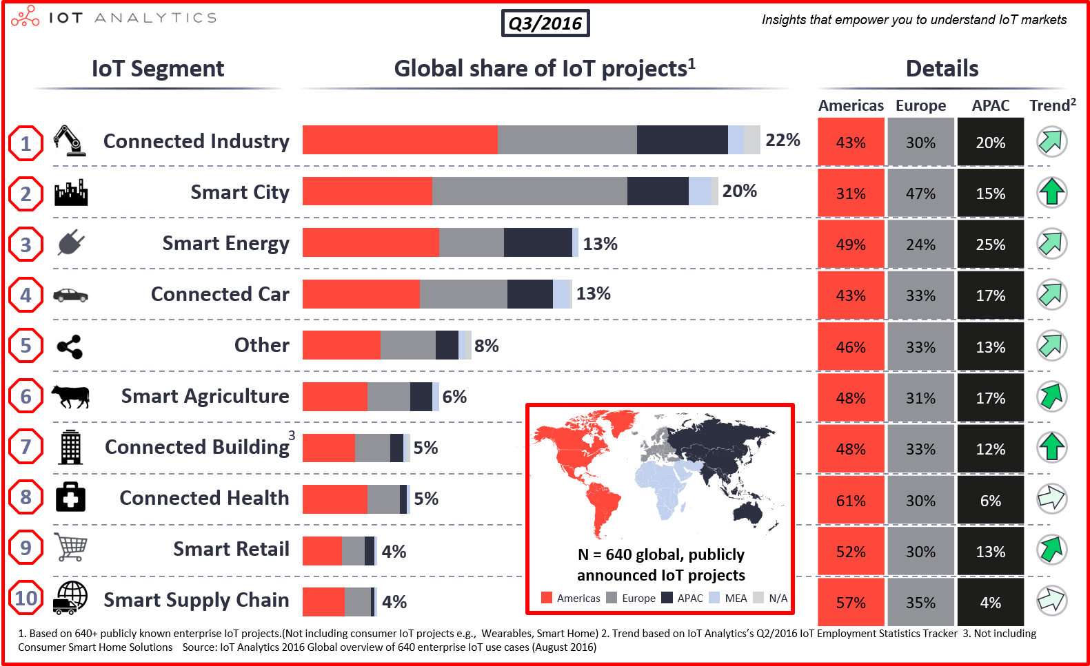
According to IoT Analytics, in 2016, the most projects (22% of the total) related to the use of the Internet of things, were implemented for industrial facilities. This confirms the development and distribution of technologies stated in the Doctrine of Industry 4.0 .
Thus, before our eyes, a new class of cyber-physical systems emerged, called Industrial Internet Control Systems (IICS) or Industrial Internet of Things (IIoT).
')
From the title it is clear that such systems are a hybrid of technologies used in process control systems and systems based on the Internet of things. Accordingly, in such systems it is necessary to take into account all the risks associated with the violation of the properties of information (security) and functional safety (safety).
This article continues the cycle of publications on functional safety . It discusses the requirements for the organization of the life cycle of control systems (process control systems, embedded systems, the Internet of things). A unified structure of processes supporting the fulfillment of requirements for both information and functional security is proposed.
When reviewing the information security requirements of the automated process control system, we managed to harmonize the information security (IS) and functional security (FB) requirements (see Figure 1). As can be seen in the figure, the processes of ensuring information security and security security should be implemented within a single life cycle.
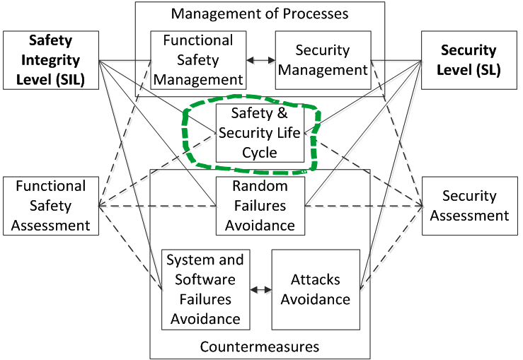
Figure 1. The structure of requirements for information security and security tools
"Big" life cycle
Since this is, first of all, a process control system, their life cycle is usually considered in relation to an industrial control object. Therefore, the so-called “large” life cycle is considered, which is associated with the design, construction, operation and disposal of an industrial facility, where the APCS is one of the components. Of course, modernization of the existing equipment for the process control system can be carried out, but this also fits into the “large” life cycle.
Let us look at what IEC 61508 says: “Functional safety of electrical, electronic, programmable electronic safety-related systems” (IEC 61508 Functional safety of electrical / electronic / programmable electronic safety-related systems). The first part of this standard contains an “epic” drawing relating to the life cycle of an industrial object. The names of the stages speak for themselves. The following steps directly relate to the process control system (marked with green asterisks in Figure 2):
- 1 Concept;
- 9 Electrical / electronic / programmable electronic (E / E / PE) system safety requirement;
- 10 E / E / PE system;
- 12 overall installation and commissioning;
- 14 Overall operation, maintenance and repair;
- 15 Overall modification and retrofit;
- 16 Decommissioning or disposal.
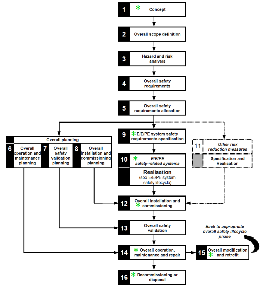
Figure 2. IEC 61508-1, Figure 2 - Overall safety lifecycle
("*" Marks the steps applicable to the process control system)
V-shaped ("small") life cycle
The concept, specification of requirements and implementation are described by the so-called V-shaped or “small” life cycle. Sometimes the concept is taken out of the framework of the “small” life cycle, but we will include it, since it must contain initial positions for forming the specification of requirements.
Further, IEC 61508 discloses the structure of the “10 E / E / PE system realization stage” (see Figure 3). The structure of the implementation process is proposed for both software and hardware, with the programmable component (for example, FPGA, programmable integrated circuits) and the non-programmable component being different for the latter.
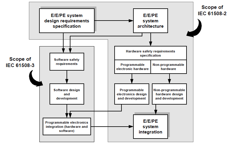
Figure 3. IEC 61508-2, Figure 4 - Relationship between the scope of IEC 61508-2 and IEC 61508-3
IEC 61508 contains several inaccuracies and gaps related to the structure of the system life cycle. This is due to the fact that an attempt was made in the "small" life cycle to separate the requirements for software and hardware, and to present the system level in the "large" life cycle.
Thus, one of the problems of IEC 61508 is that it does not explicitly contain a life cycle that could be directly applied to computer control systems, whether it is a process control system, embedded systems, or the “Internet of things” device level.
Usually in the practice of software and systems engineering, we are talking about the development of the system before the transfer to the supplier. We will consider in detail just such a V-shaped life cycle. The structure of the life cycle is defined by standards for functional safety, including IEC 61508 (see Figure 4). On the descending branch of the life cycle is the development of "top - down". The bottom-up integration is performed along the upstream branch of the life cycle, followed by testing for compliance with various project documents.
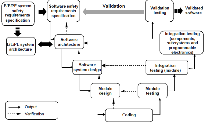
Figure 4. IEC 61508-3, Figure 6 - Software systematic capability (the V-model)
For a detailed study of the life cycle of the proposed author's interpretation, proven on their own experience in several successful projects for certification. The proposed life cycle structure, on the one hand, does not contradict the requirements of IEC 61508, but on the other hand closes some gaps in the requirements, showing how it is possible to integrate the development, verification and validation of the system, software and hardware within a single model.
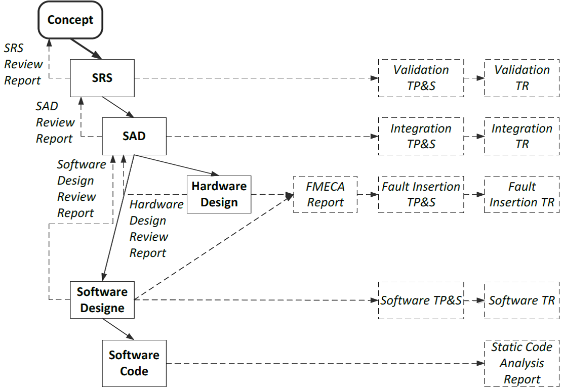
Figure 5. The life cycle of information and functional security
The life cycle model includes the following successive steps (in Figure 5, the steps are indicated by the names of the final documents):
- concept development (Concept);
- development of a safety requirements specification (Safety Requirements Specification, SRS) describing the system in the form of a “black box”, that is, “what is being done”, and not “how it is being done”;
- a review of the safety requirements specification (SRS Review) is a step in the verification and validation process;
- development of the project of the system architecture (System Architecture Design, SAD), describing the system in the form of a “white box”, that is, “how it is performed”, and not “what is being done”;
- Review of the system architecture project (SAD Review), is a stage of the verification and validation process;
- development of the hardware design (Hardware Design), in Russian terminology this component is called the design documentation (CD), it includes both the projects of electronic boards and drawings of mechanical structures and electrical parts (the so-called "strapping"), including cables, components of power supply and interfacing with field equipment (sensors and actuators;
- a hardware design review, a step in the verification and validation process;
- analysis of types, consequences and criticality of failures (Failure Mode, Effect and Criticality Analysis, FMECA), is the stage of the verification and validation process; when performing FMECA, the hardware structure is primarily taken into account, however, the diagnostic and fault tolerance mechanisms implemented in the software are also taken into account;
- software design (Software Design);
- software design review (Software Design Review), is a stage of the verification and validation process;
- software code development (Software Coding);
- static analysis of program code (Static Code Analysis);
- software testing for compliance with project requirements (Software Testing) includes both unit- and integration testing, both functional and structural testing; Before testing, a software test plan and specification is developed (Software Test Plan and Specification, TP & S), the test results are documented in a software test report (TR);
- testing by the method of seeding defects in hardware and software (Fault Insertion Testing), the input for which are the results of FMEDA in terms of the analysis of the implementation of self-diagnosis; Before testing, a plan and specification of testing by the method of seeding defects (Fault Insertion TP & S) is developed, the test results are documented in the test report by the method of seeding defects (Fault Insertion TR);
- integration testing of integrated software and hardware components for compliance with architecture requirements (Integration Testing); Before testing, a plan and specification for integration testing (Integration TP & S) is developed, the test results are documented in the integration testing report (Integration TR);
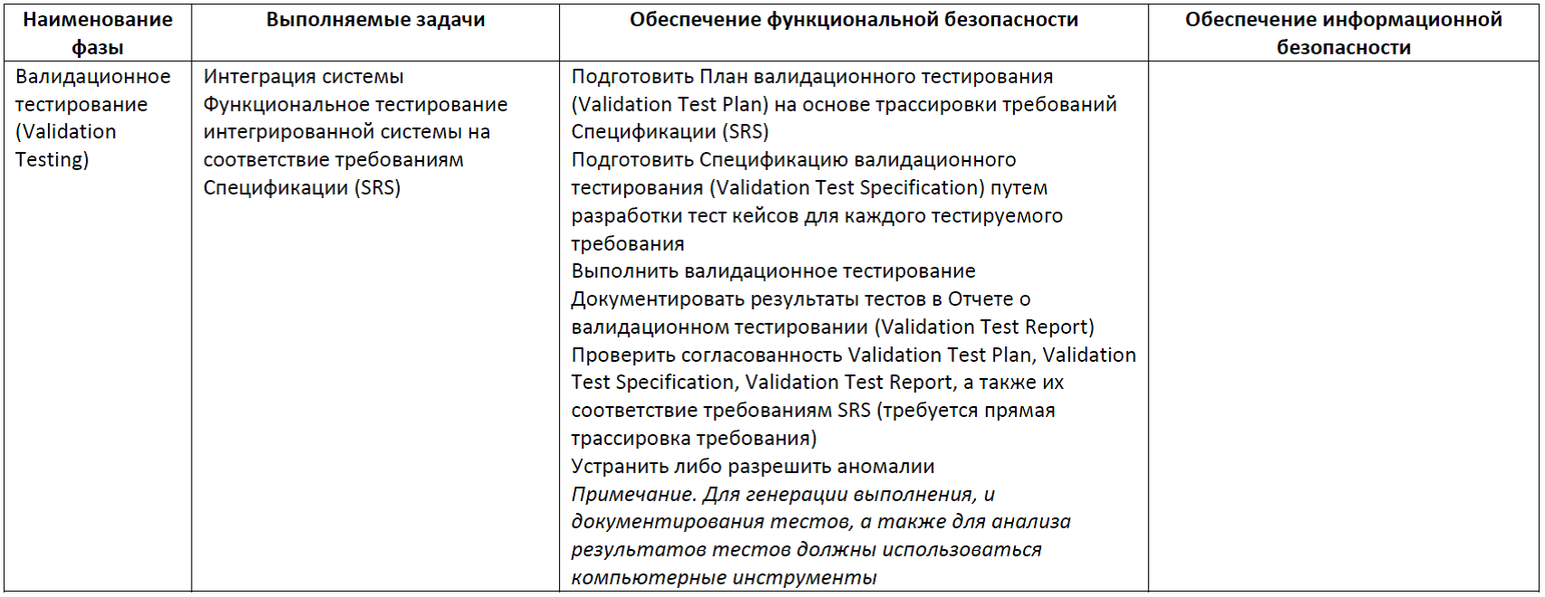
- validation testing of the integrated system for compliance with the safety requirements specification (Validation Testing); Before testing, a plan and specification of validation testing (Validation TP & S) is developed, the test results are documented in the Validation TR report; Considering the importance of this final phase of the life cycle, IEC 61508 requires that a validation test plan be drawn up immediately after the development of a safety requirements specification (SRS); Validation may include, in addition to functional testing, also testing for resistance to extreme environmental influences (temperature and humidity, mechanical, electromagnetic, radiation, etc.).
Life cycle phases
A detailed description of the phases of the life cycle is presented in the form of a set of tables. The tables synchronize activities to ensure both functional and information security. Some actions can be attributed simultaneously to both FB and IB. For computer control systems, the main risks relate to violations of the FB property. Therefore, priority is given in the table. Those actions that provide and FB, and IB are included in the column relating to the FB. Accordingly, the column relating to IS takes into account actions that are not overlapped by the activities of providing security. I understand that all this looks a bit boring, however, the proposed material can be used as a reference.
Table 1. Concept Phase
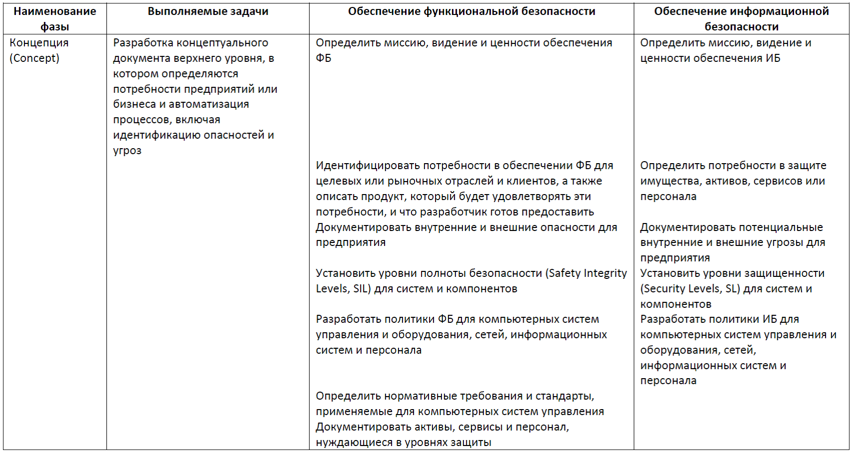
Table 2. Phase Safety Requirements Specification
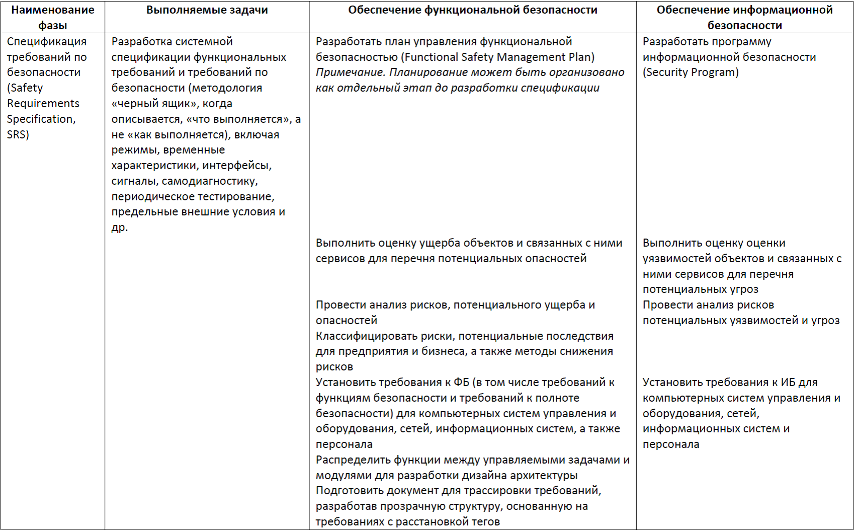
Table 3. Phase Safety Requirements Specification Review
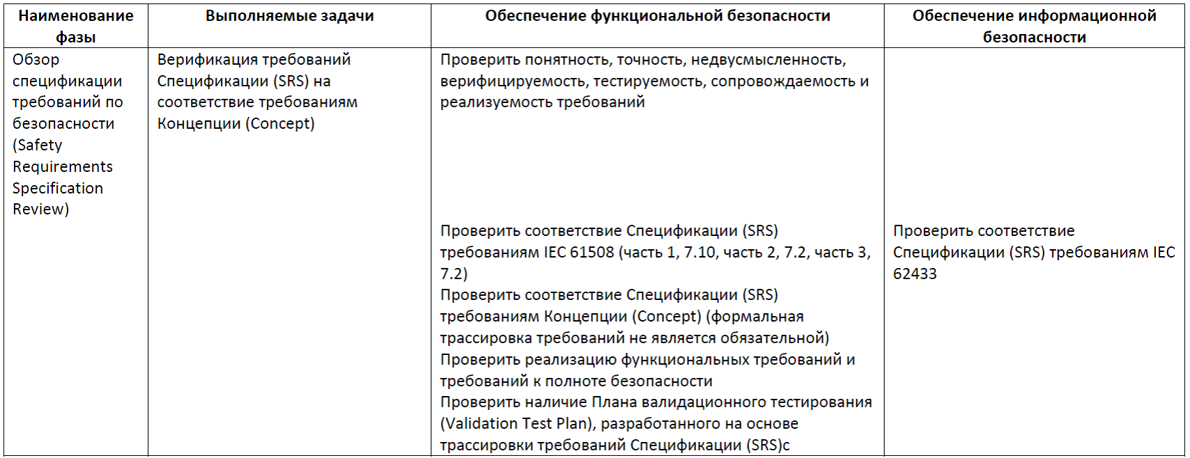
Table 4. Phases of System Architecture Design, System Architecture Design Review
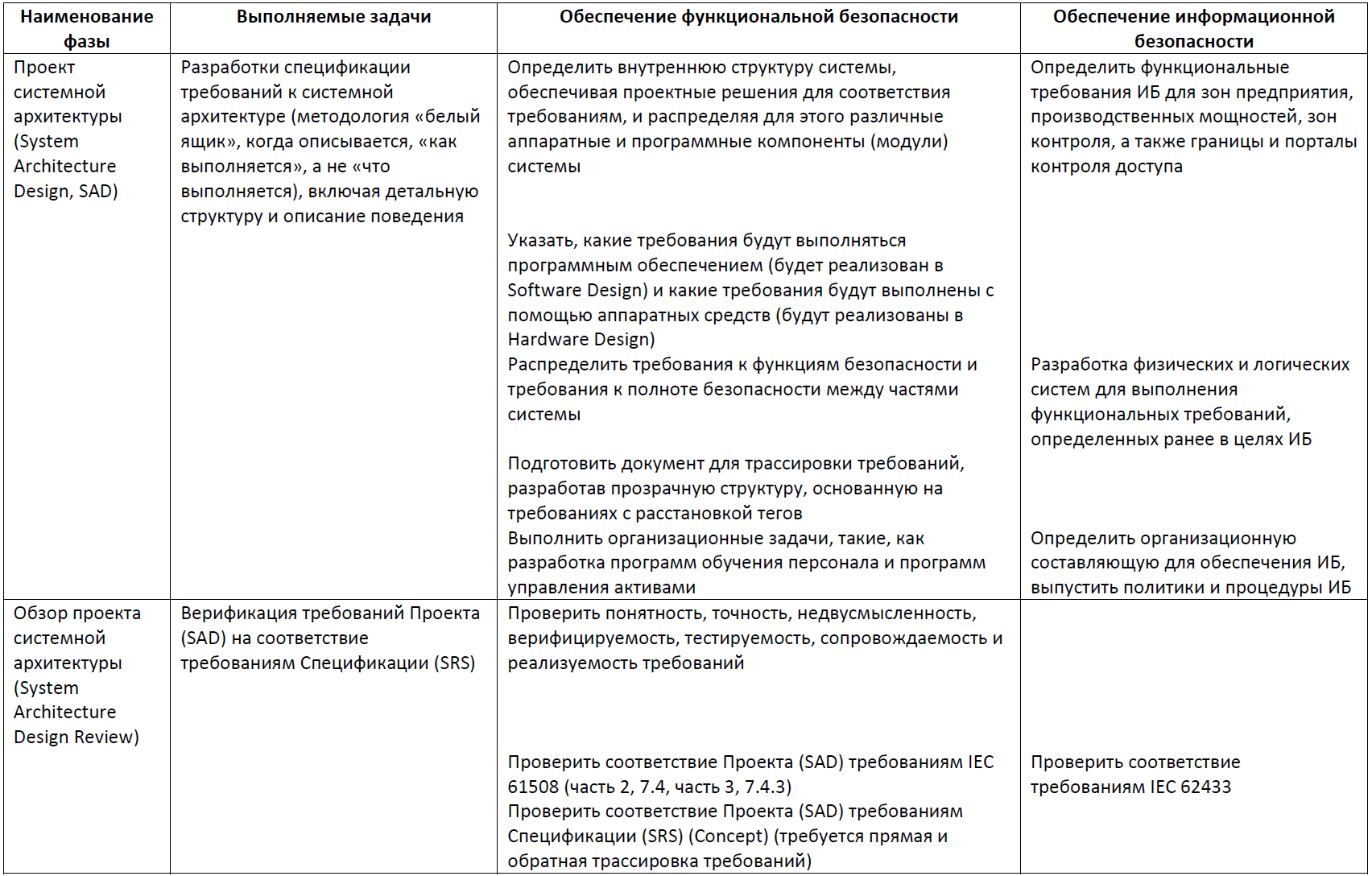
Table 5. Hardware Design, Hardware Design Review Phases
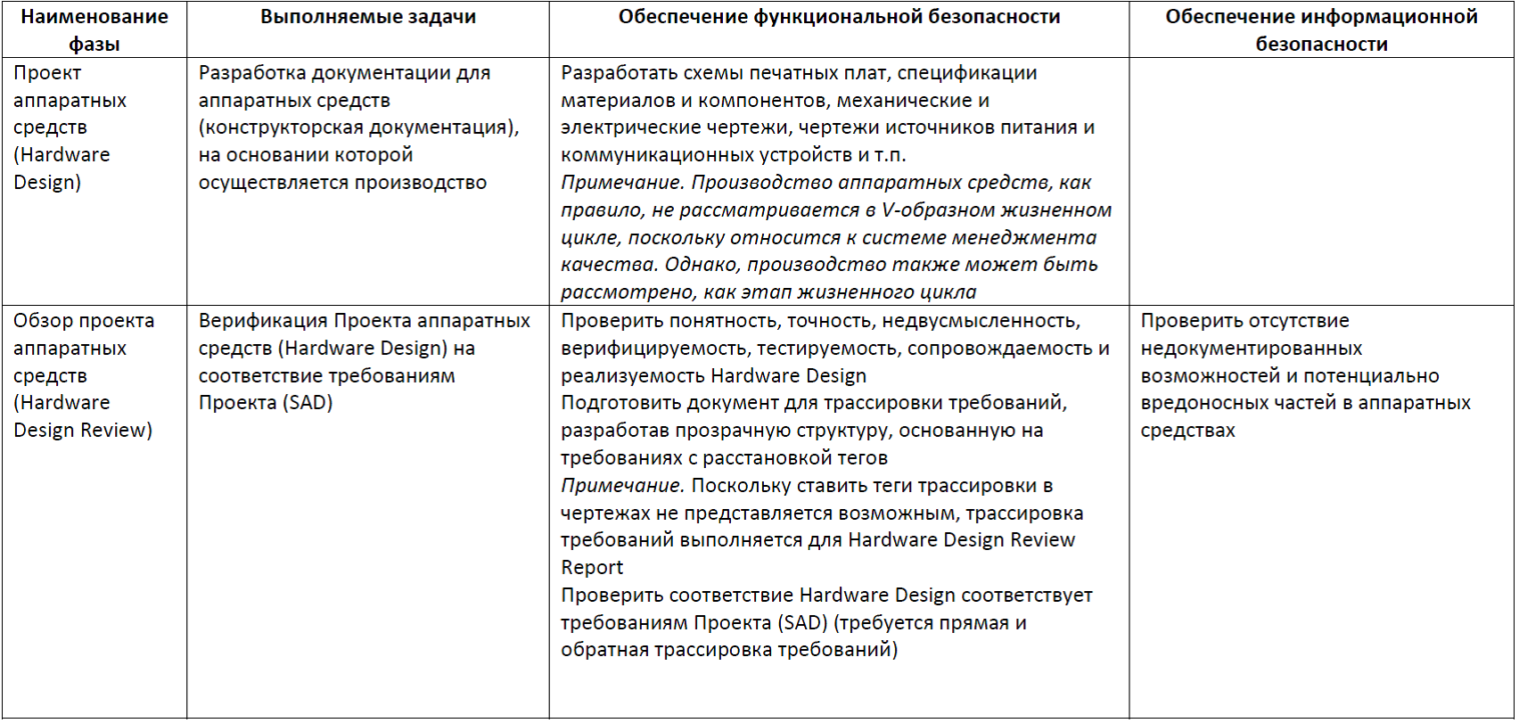
Table 6. Failure Mode Phase, Effect and Criticality Analysis
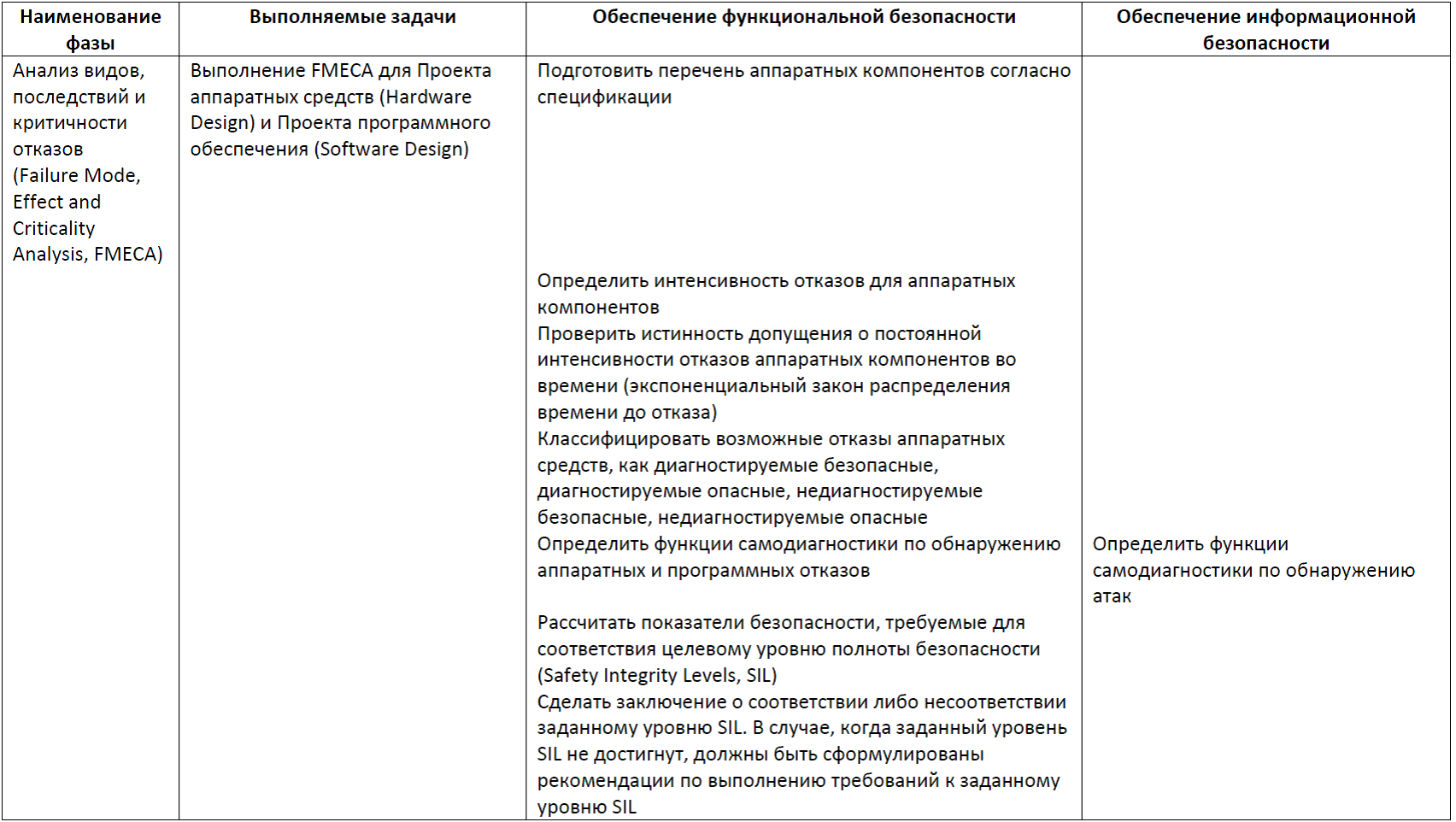
Table 7. Software Design, Software Design Review, Software Coding, Static Code Analysis
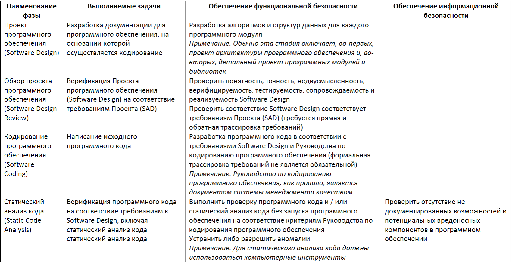
Table 8. Software Testing Phase
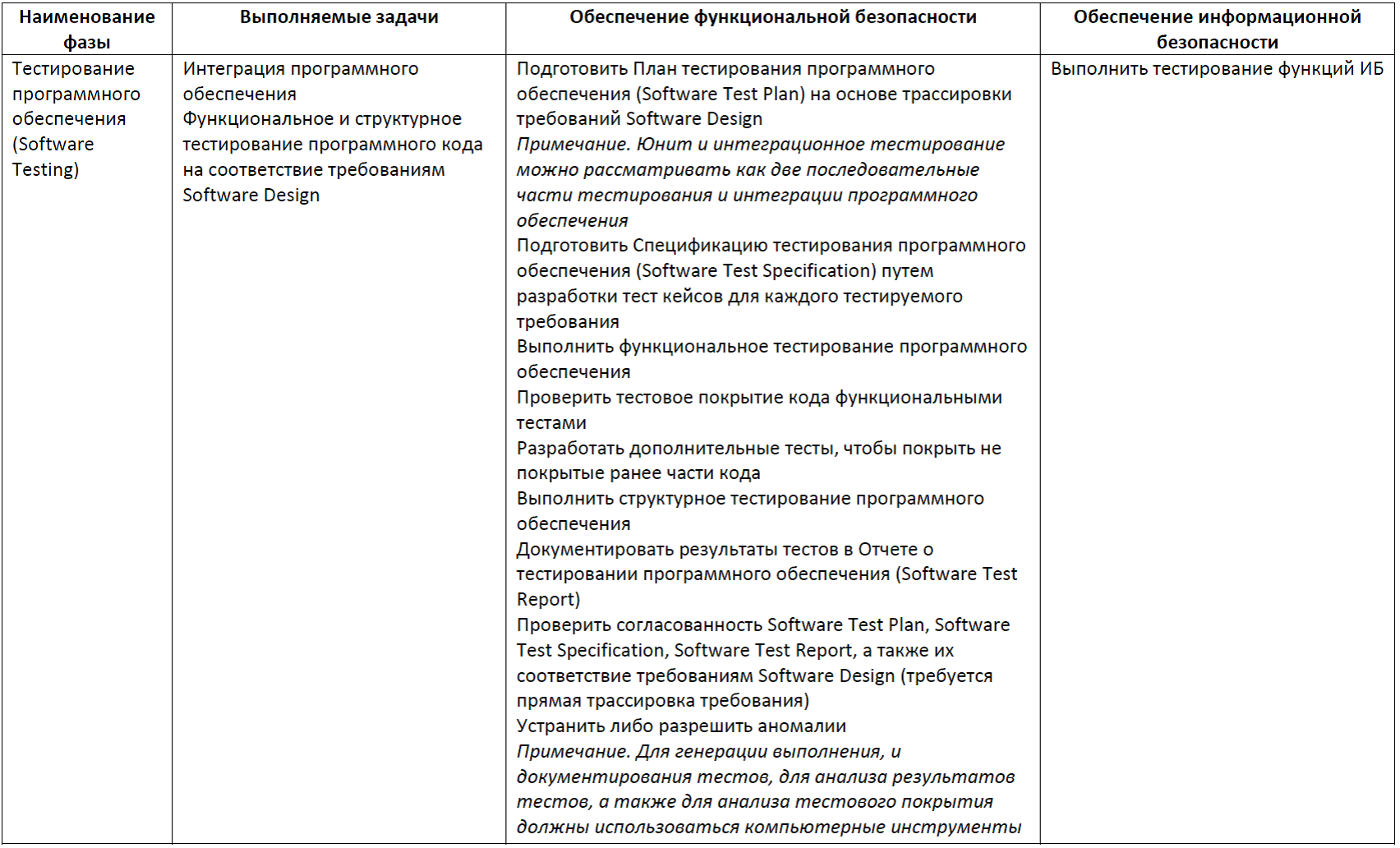
Table 9. Fault Insertion Testing Phase
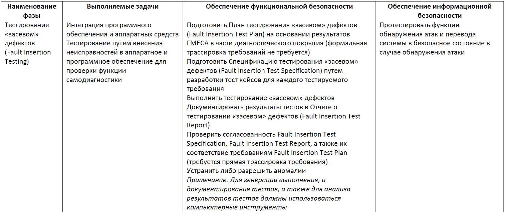
Table 10. Integration Testing Phase
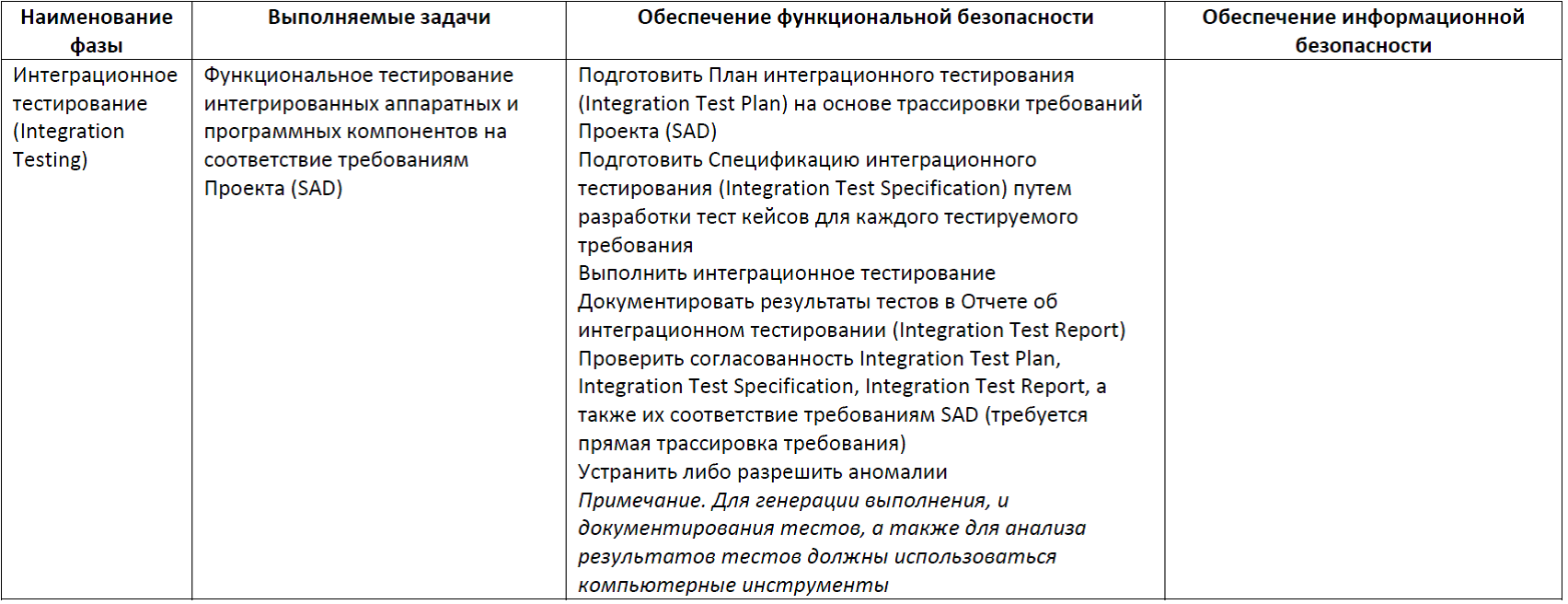
Table 11. Phase Validation Testing
Tracing requirements
Requirements tracing is one of the processes in a wider area of expertise called Requirements Engineering.
A requirement is a documentary representation of a condition or property to which a system or system component must comply in order to satisfy a contract, standards, specifications, or other formal documents.
Requirements tracing is a method for managing changing requirements and related artifacts. Tracing requirements solves three main tasks:
- ensures the implementation at the lower level of all the requirements of the upper level,
- prevents undocumented functions from appearing on the lower level,
- provides testing of all requirements.
Consider the example of how tracing is performed (see Figure 6). An example is taken from the RadICS controller certification project . To perform trace requirements, documents must be prepared for this process by placing requirements identifiers and tags that define the boundaries of the wording of the requirements.
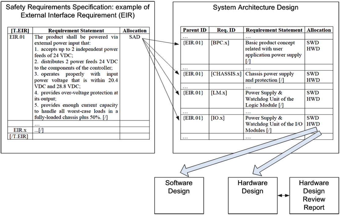
Figure 6. Requirement trace example
On the left is a fragment of the Safety Requirements Specification. The document is developed in tabular form. For each of the requirements, an identifier is entered, in this case EIR.01, requirements for the power supply interface. Scanning a document for tracing is done with exida's DEUS tool. DEUS is an MS Office macro. The beginning of the request is determined by the identifier, and the end of the requirement by the character [/]. In the Allocation field, a low-level document is specified where the specification requirements are traced. In this case, this is System Architecture Design. In System Architecture Design, the requirements must also be tagged with tags. In addition, for each of the requirements, its source should be indicated in the top-level document, the so-called parent requirement. For our requirement, the one-to-many relationship turned out, that is, the power supply requirement was reflected in the requirements for both the basic product concept, and the chassis, and all modules. Each of the SAD requirements is then traced to the Hardware Design & Software Design. The final trace results can be represented as a set of matrices reflecting the relationships between the requirements of the documents. Requirements are traced backward from low-level documents to high-level documents to make sure that the product does not have extra undocumented functionality.
When testing, tracing is done by extracting requirements from project documents. For complex projects, the development of test documents can take place in two stages. First, a test plan is developed, containing a list of test requirements, and then test cases are developed for each requirement in the test specification. During testing, direct tracing of requirements is carried out from the project document to the plan and test specification, and then to the testing report. For testing by the method of seeding defects, the list of tests is extracted from the FMECA report by analyzing the diagnosed failures. For a reasonable set of failures, a set of tests is made, on which diagnostic functions are checked. Backtracking is not critical here, because if additional tests are performed that are not due to project documents, this will not affect security.
findings
The fourth industrial revolution (Industry 4.0) poses challenges related to ensuring information and functional security for a new type of system, Industrial Internet Control Systems (IICS) or Industrial Internet of Things (IIoT). In this regard, it is important to take into account the complex requirements for information security and security. As part of the strategy to implement the requirements for information security and security tools, this article describes the structure and content of the stages for the Safety & Security Life Cycle.
Another challenge is the training of specialists capable of developing, evaluating and operating a new class of systems (IICS, IIoT). Obviously, such specialists must possess technologies in two domains: the automated process control system and the Internet of things. Our universities do not yet prepare such specialists in large quantities, and in the market of automated process control systems and the Internet of Things, as a single technology stack, they are not yet “friends”, although this is a matter of time.
PS To explain the main aspects of functional safety, the following cycle of articles is developed:
- Introduction to the subject of functional safety ;
- Standard IEC 61508: terminology ;
- IEC 61508 Standard: requirements structure ;
- The relationship between information and functional safety of the process control system ;
- Management processes and functional safety assessment ;
- The life cycle of information and functional security ;
- The theory of reliability and functional safety: basic terms and indicators ;
- Methods to ensure functional safety .
Here you can watch video lectures on the topic of publication.
Source: https://habr.com/ru/post/322428/
All Articles