Mustached shooter of twenty-three polygons
And let's digress a bit and write a game in google play? And not such a huge and heavy garbage, about which I usually write articles, but something simple and sweet to the heart?
In fact, everything is very simple: I finally registered a developer account and really want to try it out. At the time of writing these lines, I do not have a single written class and not a single drawn pixel. In essence, this article is a real devlog.
Articles
- First part. Mustached shooter of twenty-three polygons.
- The second part of. Mustached shooter with a polygonal belly.
Table of contents
- Idea
- Microprototype
- First map
- The choice of setting and visual style
- Transition to 3D
- Procedural generation
- Regular polygons in 2D
- Regular polygons in 3D
- Shadows
- Shadows in the Vertex Shader
- Generate shadows on cpu
- Shadow Optimization
- Conclusion of the first part
 Level 1.1. Idea
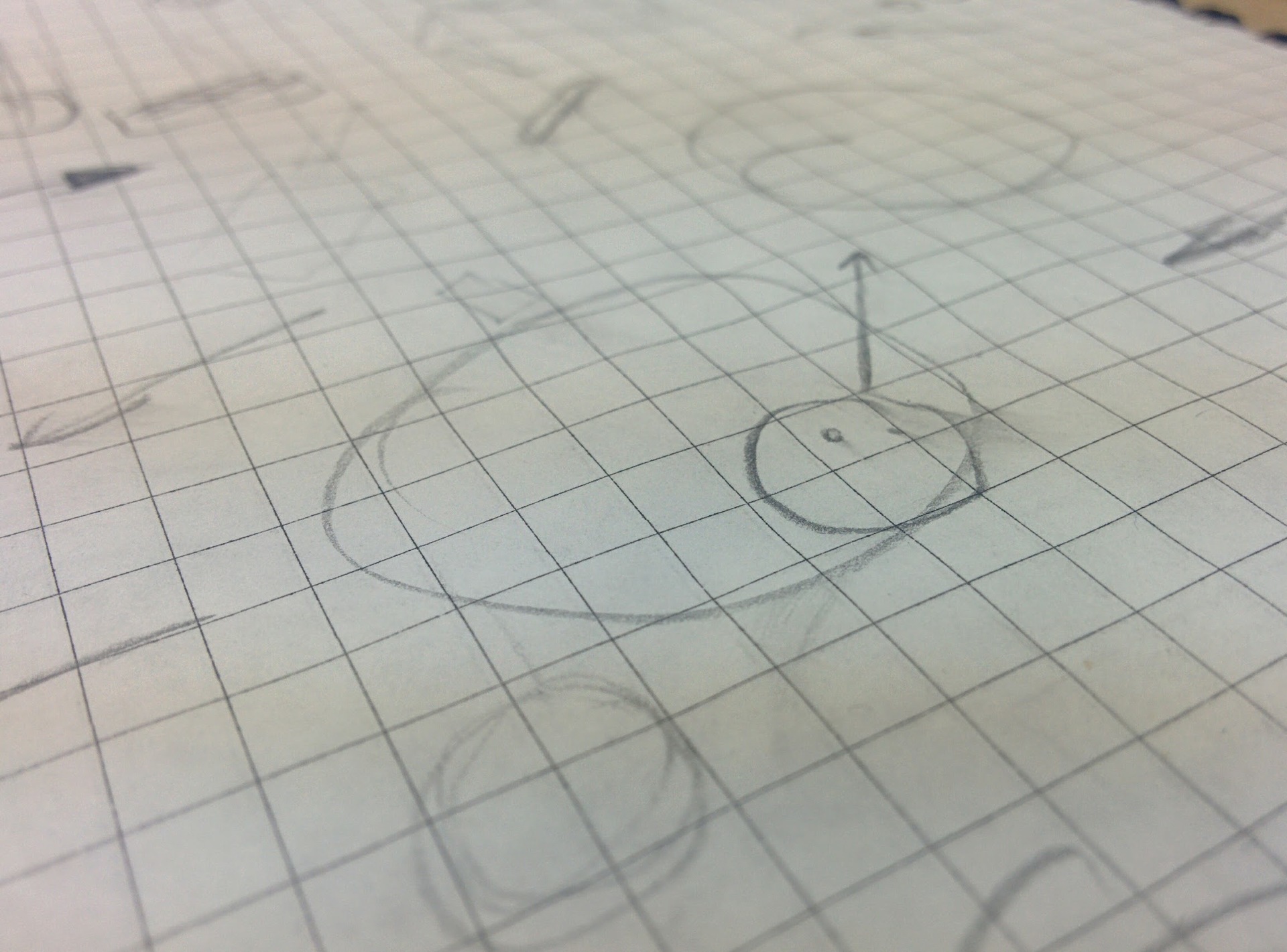
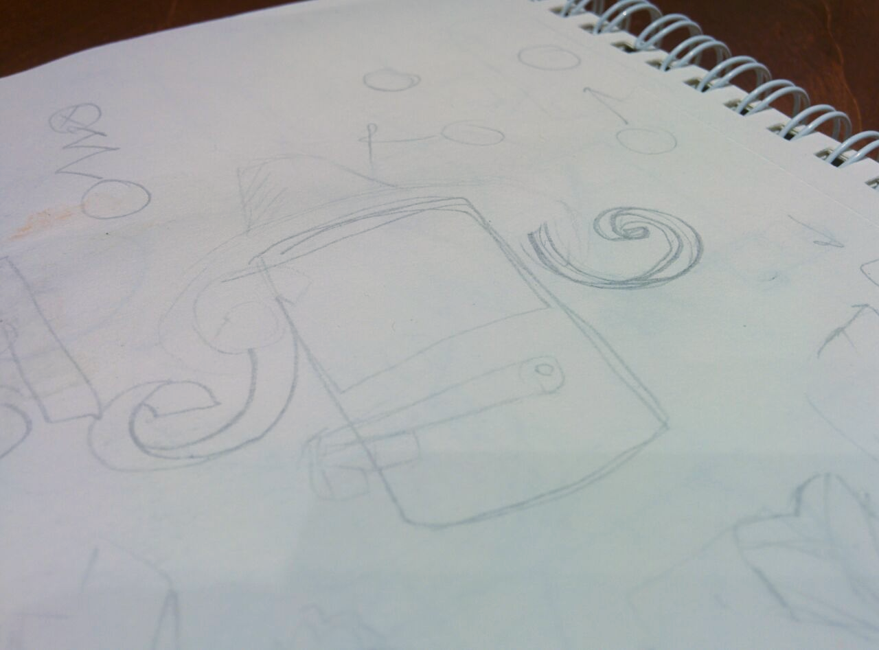
The first kalyaki-malyaki.
See this circle on paper? From him and begin. It seems to me that any game (oh well, any piece) can be started with a similar circle. What will he be in a few seconds? Wheel? Hat? Planet? I draw doodles, trying to imagine what this circle means. Hat!
A certain stern uncle walks along the roads, and we look at him from above. Severe - because he knows how to shoot with a pistol. Stomping around the city, blowing into his mustache, shooting bullets at the bandits.
This blank is just an image that has long been spinning in my head. That's just to make the game on the likeness of Crimsonland absolutely do not want to do. And I always disliked gui with two joysticks. We cut off all unnecessary with the Occam's razor and get the following concept at the output:
Level: a small town with houses, drawers and barrels.
Characters: the main character (shooter), gangsters and pedestrians.
The game is paused and waiting for the player to act. The player makes a swipe in any direction. In this moment:
1. Time in the game starts to go;
2. The main character shoots in the direction indicated by the player;
3. The main character begins to move in the indicated direction.
It takes half a second and the time in the game stops again. The player needs to defeat all the bandits, injuring as few passers as possible.
This combination of automatic shooting and stopping time I really liked:
- Automatic shooting:
- Simplifies control (one svayp instead of two joysticks);
- Adds an interesting mechanic (you have to look where you are going, so as not to shoot at a passerby).
- Stop time:
- Adds variability to the gameplay (you can do different levels: slow, thoughtful puzzles or a smart shooter);
- Softens the complexity of automatic firing;
- It allows you to control the dynamics of both me (through level design) and the player.
Gradually, the idea is visualized and overgrown with details. Mark one after another, enough for today.
Todo: make a tiny prototype and check how far the fan will move / shoot with the time stop.
 Level 1.2. Microprototype
Thanks Unity3D, prototyping on it is very simple. I add a couple of walls with BoxCollider2D , round sprites with RigidBody2D and CircleCollider2D (player, passers-by and bandits). Bullets - the same sprite, only small, red, with RigidBody2D , CircleCollider2D and TrailRenderer for the flight path.
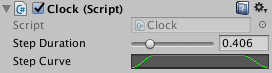
Time management I do through my Clock class, all other classes (player, bullet, etc.) use the time delta from it, not Time.DeltaTime.
using UnityEngine; using System.Collections; public class Clock : MonoBehaviour { [SerializeField, Range(0, 2)] float stepDuration; [SerializeField] AnimationCurve stepCurve; float time = -1; float timeRatio = 0; float defaultFixedDeltaTime = 0; static Clock instance; public static Clock Instance { get { return instance; } } void Start() { instance = this; defaultFixedDeltaTime = Time.fixedDeltaTime; } void OnDestroy() { if (instance == this) instance = null; } public bool Paused { get { return time < 0; } } public float DeltaTime { get { return timeRatio * Time.deltaTime; } } public float FixedDeltaTime { get { return timeRatio * Time.fixedDeltaTime; } } public void Play() { if (!Paused) return; time = 0; timeRatio = Mathf.Max(0, stepCurve.Evaluate(0)); UpdatePhysicSpeed(); } public void Update() { if (Paused) return; time = Mathf.Min(time + Time.unscaledDeltaTime, stepDuration); if (time >= stepDuration) { timeRatio = 0; time = -1; UpdatePhysicSpeed(); return; } timeRatio = Mathf.Max(0, stepCurve.Evaluate(time / stepDuration)); UpdatePhysicSpeed(); } void UpdatePhysicSpeed() { Time.timeScale = timeRatio; Time.fixedDeltaTime = defaultFixedDeltaTime * timeRatio; } } The most basic prototype is ready in an hour and a half, full of bugs:
- The movement of the player and the bullet is done through the transform.position, not the velocity, so the player sausages when he presses against the walls;
- Stopping time does not stop physics (fixedDeltaTime does not change), so in the pause mode, the characters move slightly (pushed out of each other).
But even in this version it is already interesting to move and shoot. The first prototype looks, of course, quite unpresentable:
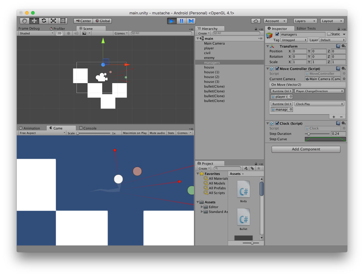
The first playable prototype
But the next day the hailstorm appears:
Chips:
- Add "reflective" walls, from which the bullet will bounce;
- Add the destruction of bots in a collision with a bullet (as long as they do not know how);
- Add flexible time management (now there is a duration and a curve for the “time flow rate”, but this is inconvenient).
Fixes:
- Transform motion to change velocity, not transform.position;
- Prohibit the creation of bullets in the walls (the player rests against the wall, shoots, the bullet immediately kills the player).
Todo: make a test learning level with invented chips.
 Level 1.3. First map
While walking down the street, I came up with a test level plan:
- Safe zone. The player learns to walk, all the bullets go to the walls;
- Narrow corridor with an inactive enemy. The player goes along the corridor and understands how to attack;
- Expansion of the corridor with an inactive gangster and a couple of passers-by. Expansion - after turning, so the player can not accidentally get into a passerby;
- Turn in the form of a periscope , instead of a mirror - a reflecting wall, around the turn - an inactive enemy. The player shoots the wall, sees how the rebound works;
- Corridor with mirrored walls, enemies and pedestrians. The player passes neatly along the corridor, trying not to get into the passers-by (or shoots them if he wants);
- Sandbox.
Throwing objects onto the stage, repainting the reflective walls in yellow. It turns out something like this: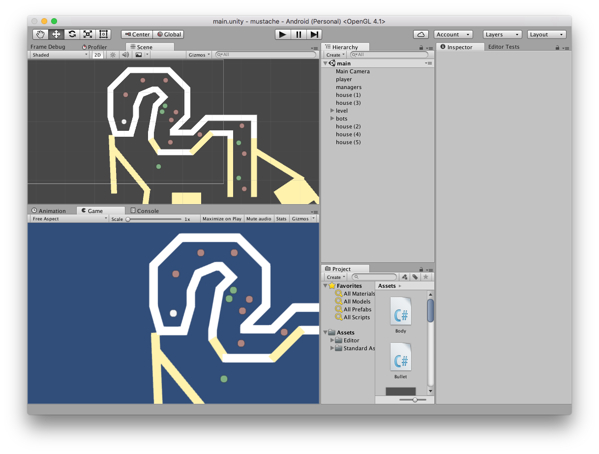
Type of training level
I make reflective walls through a separate layer, the code of the collision of a bullet with an obstacle becomes:
void OnCollisionEnter2D(Collision2D coll) { int layer = 1 << coll.gameObject.layer; if (layer == wall.value) Destroy(gameObject); else if (layer == human.value) { Destroy(gameObject); var humanBody = coll.gameObject.GetComponent<Human>(); if (humanBody != null) humanBody.Kill(); return; } else if (layer == wallMirror.value) { Vector2 normal = Vector2.zero; foreach (var contact in coll.contacts) normal += contact.normal; direction = Vector2.Reflect(direction, normal); } } I fix bugs, add chips thought up last day. I am redoing the class Clock: earlier the course lasted stepDuration of real seconds, and the coefficient of the speed of time was determined by the curve stepCurve . The curve is needed for a smooth start and completion of the course.
Old settings in Clock.cs
That's only if you change the duration of the stroke, the duration of the start / end will also change (where the value of the ordinate on the curve is not equal to 1). And if the turn-on time is too short, the “on” time seems too sharp, and when it is on the order of a second, it is too slow (because the curve is “stretched” for the entire duration of the turn). I add separate curves for the start and end of the turn, as well as the duration of the start / end.
Add a camera that monitors the player and the visualization of the player's trajectory.
I silently show the prototype to several acquaintances, explaining neither the goal, nor the control. Everyone was able to deal with the management, but there are problems that I did not notice. For myself, I recorded the conclusions of the playtest:
- Difficult to aim. I use the delta between the last two positions of the finger, I would need to take more values;
- Finger gets tired to swipe across the screen. It is solved by the duration of the course, level design;
- Sometimes lost swipe made. People start to make svayp, when the turn is not over yet and often release the finger while the current turn stops. Since during the course it is impossible to change the direction, the gesture is wasted. It is solved with a tricky code (I don’t know how)
- It would be cool to make collected objects that are destroyed by bullets. They need to be approached, but not in a straight line;
- Ricochets add interest: you can arrange a mad bullet storm;
- Players do not distinguish between passers-by and enemies. It is treated by art;
The prototype is ready so that you can show the gameplay!
Todo: decide on the setting, graphics.
 Level 1.boss [100hp]. The choice of setting and visual style
My first “boss” was precisely this stage, I never thought. I planned the following: surf the Internet on popular gaming settings, search references and art for inspiration, and start drawing levels in pixel art.
After some googling, I decided to dwell on the entourage of Victorian England. Ferns, the cult of death, gloomy docks. Wood, metal, steam and oil.
I try to draw the first sprites and discover the problem. All objects in the game can rotate. And the pixels, as you know, no.
Drawing 360 variants of each sprite is obviously not an option. Fortunately, now the fashion is not the "dishonest pixelart", when the sprites rotate freely around its axis. In this case, you need to do something with the aliasing ladders, which inevitably appear, predatory angular faces will stick out and will flicker here and there. You can put up with it and say: “This is my style!”, As the creators of Hotline miami did (and in fact it turned out!). You can connect anti-aliasing: "Long live fragrant soap!".
In any case, I did it: either aliasing and ladders, or fuzzy edges after anti-aliasing.

Test pixelart
I mark the pixelart (sorry, friend!) And simplify, simplify!
Todo: choose the appropriate visual style.
 Level 1.boss [75hp]. Transition to 3D
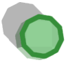
City of paper! Looks a bit like Wildfire worlds , only easier. Noble white faces of rough paper, spots of paint on the floor, these are the characters in funny hats:
Cylindrical pax
In truth, I never worked with 3d in game dev, and 3d editors last opened a few years ago. But I know that much is solved by lighting and shadows. Especially if the texture is white paper, where you really can’t hide the disadvantages of bad light.
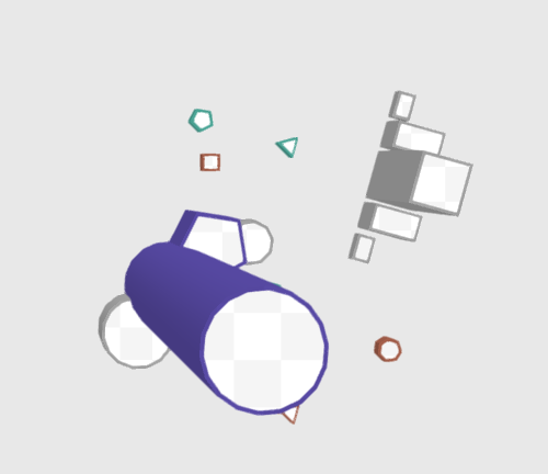
I spend the evening on the simulation of the first object: a package of milk. Understand with standard shaders, lighting.
The conclusion is simple: I will not pull. I spend a lot of time on modeling and I can not get a beautiful picture by standard means. Baking lighting helps, but I wanted to make a small toy with many levels, so baking is in flight. Looks like the boss is not defeated yet ...
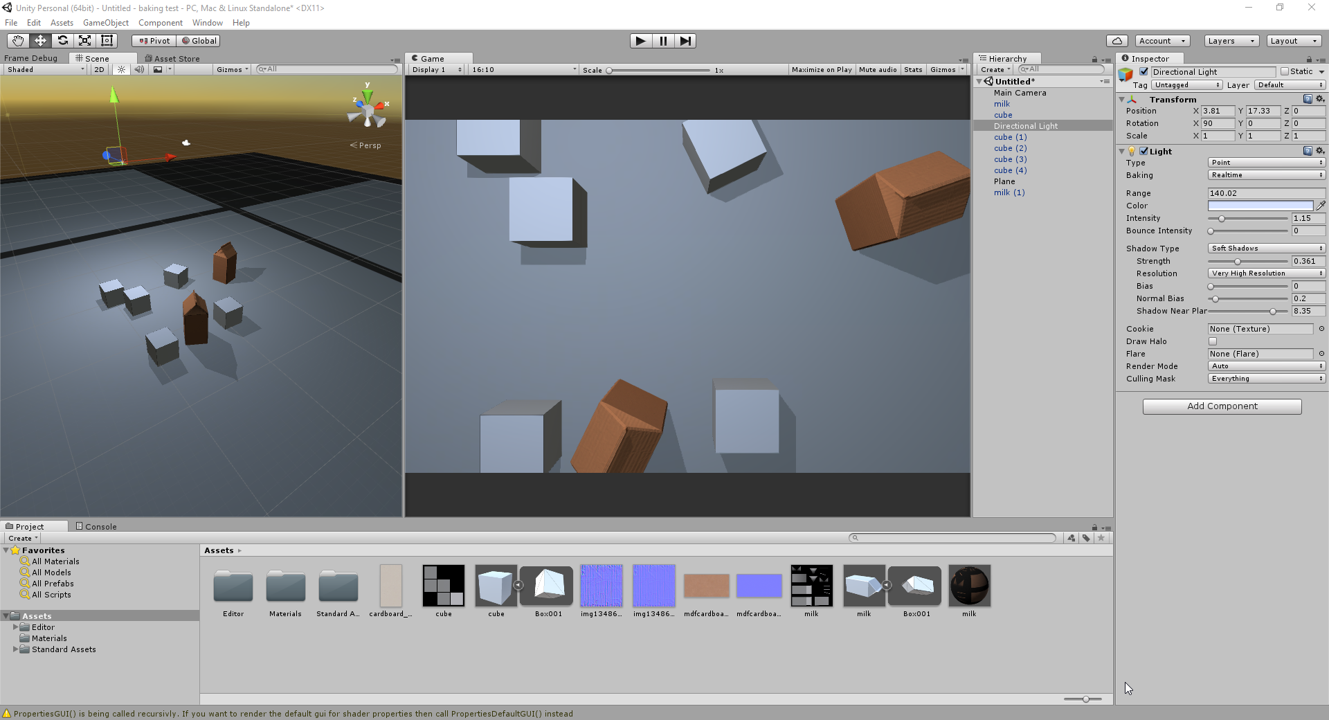
Milk pack with simple lighting
 Level 1.boss [15hp]. Procedural generation.
I remember my strengths and weaknesses. Usually, if I can't draw any art for my project, I write a script that will do it for me. Than 3d is worse? So procedural generation! Base primitives are, in fact, low poly. Bright, contrasting colors, visually encoding gameplay differences.
I need to decide what primitives I need to create levels. Cylinders and cubes, perhaps pentagons ... Hmm, this is all you can generate with one code. For the work!
Todo: implement simple primitive generation.
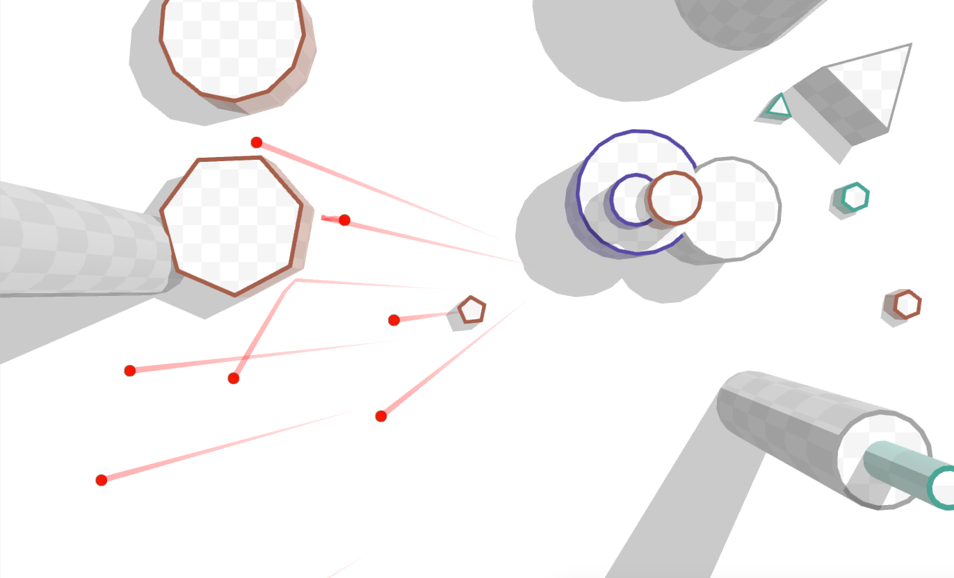
 Level 2.1. Regular polygons in 2D
For now the level will be enough regular polygons. To begin with, I decided to try 2D, turned the camera into an orthogonal mode and created elements of two pieces:
- The body (just a regular polygon) is white;
- A colored ring around, indicating in color the type of object (how the bullet will behave if it collides).
If we use the constant radius of the ring for all polygons, we get such unsuited outlines:
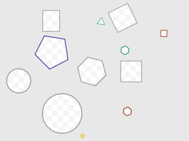
Contours of different thickness
The fact is that you need to get the same distance between the sides of the outer and inner parts of the "ring", and I work with corners, not sides. The smaller the angles in the polygon, the more radii of the circumscribed and inscribed circle will differ, and, accordingly, the distances between the sides and the distances between the corners will differ.
$ inline $ 1 - cos \ frac {\ pi} {edges} $ inline $ - solves the problem.
Now the smaller the angles, the wider the contour will be:

Contours of the same thickness
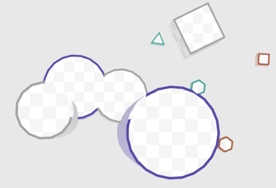
A little stencil magic, so that the rings inside other polygons are not visible and we get such a hare:

Bunny
And then spun!
I added a standard cellular texture to the body, picked up colors and finally could not resist and plugged in my favorite shadows (I wrote about them already).

Simple and neat.
I share the screen with a girl and get a reasonable feedback: the shadow falling from a high object to a lower one has distortions, breaks. I agree, I see it all the time in the real world. I try to draw on paper and understand how these distortions should look like. And here I understand: what kind of distortion, if the camera is orthogonal?

Left shadows with a perspective camera, right with orthogonal
It turns out that my beautiful shadows only emphasize the flat view of the map. Time to return to 3D.
 Level 2.2. Regular polygons in 3D
To be honest, procedural generation in 3D is a completely new experience for me. On the other hand, it should not differ from 2D.
First, I decided on the settings of a particular polygon:
- height - Height;
- edges - the number of faces;
- size - Vector2D, allows you to set the size of the polygon or stretch it along one of the axes;
- isCircle - Is it a cylinder? If yes, the number of faces is set automatically, based on the radius, and size.y becomes equal to size.x.
And with general settings that will be the same for one type of game objects:
- Color "ceiling";
- Border color;
- Border width;
- The minimum number of faces in the cylinder;
- The ratio of the number of faces in the cylinder to 1 perimeter unit.
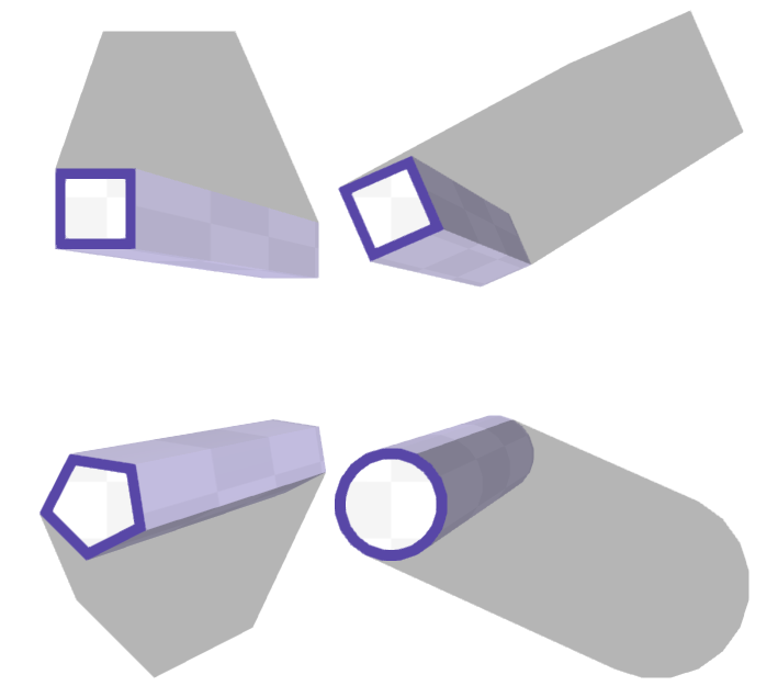
Now is the time to create these polygons. I broke each into 3 mesh:
- Body - the upper base;
- Border - color ring on the upper base;
- Side - side surface;
It makes no sense to generate the lower base, since Objects cannot rotate along the x or y axis, and the camera is always above the map.
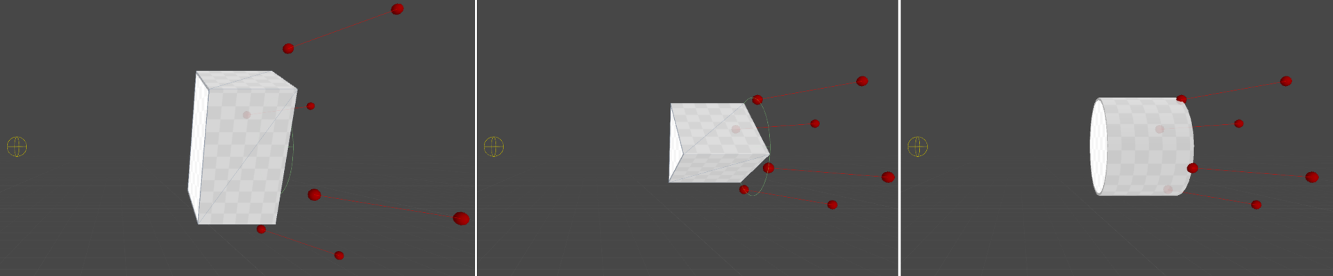
We get these polygons
Time for optimizations:
Firstly, I constantly calculate single vectors rotated at certain angles.
We get the class AnglesCache with one public method:
namespace ObstacleGenerators { public class AnglesCache { public Vector3[] GetAngles(int sides); } } Next, I cache all 3 types of meshes, using significant parameters as keys (number of sides, color, circle, etc.). I save the color to the vertices, this will allow using one material for the meshes and, as a result, dynamic batching.
True, now there was a problem with borders and stencil: I used to unite borders with stencil, now that the volume has appeared, this approach gives bad results:
The boundaries of higher cylinders are not drawn, since under them draw the base of low cylinders
I stop using stencil buffer. Now all borders must be drawn:

No stencil buffer
And finally, I change the ZTest settings in the shader from On ( LEqual ) to Less . Now the borders will not be drawn over the bases of the cylinders with the same height. As a result, I get a neat border association that correctly works with objects of different heights:

Combining boundaries through ZTest settings
Finally, the final touches:
- As uv coordinates for the bases of the cylinders I use world coordinates. All objects have a common texture without seams;
- I paint the side surface in the bleached border color;
- I add to the shader side surface _fixed3 _LightPosition, slightly illuminate the side surfaces (the classic method of rendering Guro ). Here, by the way, the isCircle flag in the objects came in handy: if it is not set, each triangle has unique vertices, if it is installed, the vertices are common. As a result, the normals are interpolated and a smooth surface is obtained for isCircle.
Lighting, anti-aliasing, shaders and world uv coordinates. (Lighting twisted harder for clarity)
The final touch is to generate PolygonCollider2D polygons of the desired shape.
Total: three-dimensional polygons with physics and neat lowpoly style.
Todo: the shadows.
 Level 3.1. Shadows
Of course, now the former two-dimensional shadows will not work:
Flat shadows look weird, because do not take into account the volume of the object
And they should look something like this:

More realistic shadows
"Well, what's the problem?" - You ask. "There are great shadows in Unity3D!"
Indeed there is. Here is the Shadow mapping algorithm that is used to build shadows. In a nutshell: If we look at the scene from a light source, then all the objects that are visible to us are lit, and those that are somehow closed are in the shadow. We can create a shadow map by placing the camera in the coordinates of the light source and rendering the scene (the z-buffer will contain the distance to the light source). The problem is in perspective distortion. The farther objects are from the light source, the more screen pixels correspond to the texels from the shadow map.
Those. The shadows are not "pixel perfect", this is not their thing, much more important that they are very fast. Usually, there is no problem with distortion, since shadows are superimposed on complex objects with a texture; as a result, a slight loss of quality is not noticeable. But I have very light textures, very few polygons, so the low quality of the shadows is perfectly visible.
However, there is a good solution. The algorithm is called " Shadow volume " and it is very similar to those two-dimensional shadows that I have done in previous articles.
Suppose we have a certain mesh, which should cast shadows from the light source.
- We find its silhouette edges (those edges that separate the lighted part of the mesh and the unlighted part);
- "Pull" them from the light source (each face turns into 2 triangles).
- We draw all these extended faces (in the color buffer we do not write anything, we only read from z-buffer, but we write to the stencil):
3.1. If the normal of the triangle is directed to the camera (front): add a unit to the stencil buffer;
3.1. If the normal of the triangle is directed away from the camera (back): subtract one from the stencil buffer.
It turns out that if we "entered" one time in the shadow (crossed the front triangle) and one - "left" (crossed the triangle back) - the value in stensile will be equal to $ inline $ -1 + 1 = 0 $ inline $ and the pixel is lit. If we entered the shadow more than the number of times we left (when there is a triangle in front of the front and back that was drawn and recorded the data in the z-buffer), the pixel is in the shadow and it is not necessary to light it.
So, you need to get the shadow meshes from the objects, go through the shader, add the necessary data to the stencil, and then draw the shadow where there is a nonzero value in the stencil. Sounds like a problem solved on shaders!
Todo: generate shadows on shaders.
 Level 3.2. Shadows in the Vertex Shader
I didn’t use a geometric shader, I don’t want to lose some devices due to the fact that the GL version is old. Accordingly, all potential edges will have to be baked in advance for each polygon.
Let there be a cylinder with 32 angles. Each face turns into two triangles and 4 vertices, total:
Total faces - 32 side, and 32 on each of two bases, 96 in total.
So, 96 * 2 = 192 triangles and 384 vertices per cylinder. Quite a bit of.
In fact, even more: initially we do not know which of the side faces will be the transition from light to shadow (front), and which one - from shadow to light (back). Therefore, for each side face, it is necessary to make not 2 triangles, but 4 (2 of them with the opposite direction of the normal), so that later you can correctly cut off the ones you need using Cull Back or Cull Front.
Therefore, 32 * 4 = 128 faces, 256 triangles and 512 vertices. Really a lot.
Creating the desired mesh is quite simple; I will not focus on this.
But the shader is very curious.
Judge for yourself: we do not need to draw all the faces, only the silhouette ones (those that separate light and shadow). So, we need for each vertex in the vertex shader:
- Find the position of the previous face;
- Calculate the values of A, B, C for a straight line passing through the current and previous face;
- Determine which side of the line is the center of the polygon;
- Determine which side of the line is the source of light;
- Repeat steps 1-4 for the next facet;
- Compare values - if one of the faces is in the light (center and source in different half-planes), and the other is in the shadow - this vertex is silhouette and it needs to be drawn;
- Find out whether to pull the current vertex, or it lies on the cylinder itself;
- If you need to stretch, find the position of the vertex in world coordinates, get the direction from the light source and move it in this direction for some distance (for example, 100 units);
For all these calculations, you have to store a large amount of data at the top:
coordinates (or offset) to the previous and next vertices, the flag — whether the current vertex should be shifted.
Imagine working!
However, this method of creating shadows contains so many fatal flaws that it becomes sad:
- A huge number of vertices and triangles. Most often, a shadow consists of two side faces, half of the lower and half of the upper edges. For a 32x carbon cylinder and an infinitely distant light source $ inline $ 16 * 4 = 64 $ inline $ points and $ inline $ (16 * 2 + 2) * 2 = 68 $ inline $ triangles. Instead, I give 256 graphics triangles and 512 vertices to the video card.
- Does not work batching. To calculate the shadows in the vertices must be in one way or another stored information about neighboring vertices (positions and normals). Accordingly, the data are tied to local coordinates in the mesh space. When batching, many meshes are combined (this changes the coordinate system to the world one) and now the vertices no longer have information about the position of neighboring points.
A large number of vertices turned out to be an unpleasant consequence of the chosen method, but a broken batching scored the last nail: 100-200 draw call on a shadow for a mobile device is an unacceptable result. Apparently, it is necessary to transfer the shadow calculations to the CPU. However, is it as bad as it seems? :)
Todo: CPU.
 Level 3.2. cpu
.
:
1.1. ;
1.2. ;
1.3. ;
1.4. , — , (lightToShadowIndex);
1.5.1 , , (shadowToLightIndex);:
2.1. lightToShadowIndex shadowToLightIndex 2 (, 4-, 2 , 2 — , );:
3.1 shadowToLightIndex lightToShadowIndex 2 ;- :
4.1 shadowToLightIndex lightToShadowIndex;
:
, ( ).
: , .
, . , 60fps 10 , 600 . ( — 6 10 ).
Todo: , 60fps nexus 5.
Level 3.3.
:
— , . , .
:
. AnglesCache, . :
using UnityEngine; using System.Collections.Generic; namespace ObstacleGenerators { public class AnglesCache { List<Vector2[]> cache; const int MAX_CACHE_SIZE = 100; public AnglesCache () { cache = new List<Vector2[]>(MAX_CACHE_SIZE); for (int i = 0; i < MAX_CACHE_SIZE; ++i) cache.Add(null); } public Vector2[] GetAngles(int sides) { if (sides < 0) return null; if (sides > MAX_CACHE_SIZE) return GenerateAngles(sides); if (cache[sides] == null) cache[sides] = GenerateAngles(sides); return cache[sides]; } public float AngleOffset { get { return Mathf.PI * 0.25f; } } Vector2[] GenerateAngles(int sides) { var result = new Vector2[sides]; float deltaAngle = 360.0f / sides; float firstAngle = AngleOffset; var matrix = Matrix4x4.TRS(Vector2.zero, Quaternion.Euler(0, 0, deltaAngle), Vector2.one); var direction = new Vector2(Mathf.Cos(firstAngle), Mathf.Sin(firstAngle)); for (int i = 0; i < sides; ++i) { result[i] = direction; direction = matrix.MultiplyPoint3x4(direction); } return result; } } } :
( ). , c .
:
Transform.TransformPoint transform.localToWorldMatrix MultiplyPoint3x4.
Vector3 Vector2 ( , ), , :
Vector2 v2; Vector3 v3; // , v2.x = v3.x; v2.y = v3.y; // v2.Set(v3.x, v3.y); // , v2 = v3; , , , .
:
. , , :
- (size.x == size.y);
- .
, — . — .
:
, : size.x == size.y ;
- :
direction = lightPosition - obstacleCenter; - LCT (L — , C — , T — , L) LC, CT (). deltaAngle — LC CT;
- directionAngle — ( OX) LC;
- firstAngle , secondAngle — LT:
firstAngle = directionAngle - deltaAngle; secondAngle = directionAngle + deltaAngle; - , — 360° / edges, — z:
fromLightToShadow = Mathf.FloorToInt(firstAngle / pi2 * edges + edges) % edges; fromShadowToLight = Mathf.FloorToInt(secondAngle / pi2 * edges + edges) % edges; - , . , firstAngle : , . , , (fromLightToShadow fromShadowToLight), :
if (linesCache[fromLightToShadow].HalfPlainSign(lightPosition) < 0) fromLightToShadow = (fromLightToShadow + 1) % edges; if (linesCache[fromShadowToLight].HalfPlainSign(lightPosition) >= 0) fromShadowToLight = (fromShadowToLight + 1) % edges; . — (Acos, Atan2) . — . , . , :
.
bool CanUseFastSilhouette(Vector2 lightPosition) { if (size.x != size.y || edgesList != null) return false; return (lightPosition - (Vector2)transform.position).sqrMagnitude > size.x * size.x; } bool FindSilhouetteEdges(Vector2 lightPosition, Vector3[] angles, out int fromLightToShadow, out int fromShadowToLight) { if (CanUseFastSilhouette(lightPosition)) return FindSilhouetteEdgesFast(lightPosition, angles, out fromLightToShadow, out fromShadowToLight); return FindSilhouetteEdges(lightPosition, out fromLightToShadow, out fromShadowToLight); } bool FindSilhouetteEdgesFast(Vector2 lightPosition, Vector3[] angles, out int fromLightToShadow, out int fromShadowToLight) { Vector2 center = transform.position; float radius = size.x; Vector2 delta = center - lightPosition; float deltaMagnitude = delta.magnitude; float sin = radius / deltaMagnitude; Vector2 direction = delta / deltaMagnitude; float pi2 = Mathf.PI * 2.0f; float directionAngle = Mathf.Atan2(-direction.y, -direction.x) - anglesCache.AngleOffset - transform.rotation.eulerAngles.z * Mathf.Deg2Rad; float deltaAngle = Mathf.Acos(sin); float firstAngle = ((directionAngle - deltaAngle) % pi2 + pi2) % pi2; float secondAngle = ((directionAngle + deltaAngle) % pi2 + pi2) % pi2; fromLightToShadow = Mathf.RoundToInt(firstAngle / pi2 * edges - 1 + edges) % edges; fromShadowToLight = Mathf.RoundToInt(secondAngle / pi2 * edges - 1 + edges) % edges; return true; } :
cpu, . , , 32 , , 42 36 ( 512 256 gpu).
:
, . — "" . , .
:
x y ( ) — c , .
bounding box:
Mesh.RecalculateBounds — . AABB .
:
- 4 : circleCenter — lightPosition, ;
- 4 — 4-, z ( 8 — , );
- .
- ( , z == 0)
- 16 — , ;
- AABB .
, , .

( )
( )

Bounding box ( )
, , .
Conclusion
, , . )
, , , . , , :
- ;
- ;
- .
:
- , , ;
- — ;
- 3 — , ;
- — .
- (, Gizmos), .
, ! )
')
Source: https://habr.com/ru/post/322262/
All Articles