First steps with STM32 and mikroC compiler for ARM architecture - Part 4 - I2C, pcf8574 and HD4478 LCD connection
I2C is a bus operating on two physical connections (in addition to the common wire). Quite a lot about it is painted on the Internet, there are quite good articles in Wikipedia . In addition, the bus operation algorithm is very clearly described here . In short, the bus will be a two-wire synchronous bus. Up to 127 devices can be on the bus at the same time (the device address is 7-bit, we will return to this later). Below is a typical diagram of connecting devices to the i2c bus, with the MK as the master device.
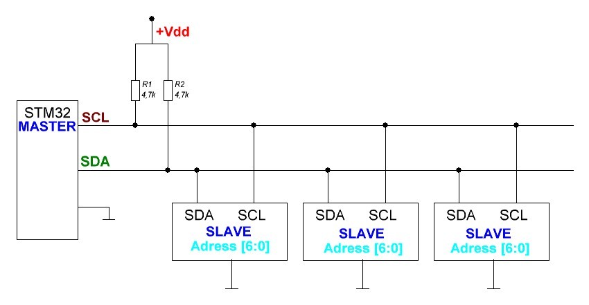
For i2c, all devices (both master and slaves) use open-drain outputs. Simply put, they can attract the tire ONLY TO EARTH. A high bus level is provided by pull-up resistors. The value of these resistors is usually chosen in the range from 4.7 to 10 kΩ. i2c is sufficiently sensitive to the physical lines connecting devices, so if you use a connection with a large capacitance (for example, a long thin or shielded cable), the effect of this capacitance can “blur” the edges of the signals and interfere with the normal bus operation. The smaller the pull-up resistor, the less this capacitance affects the characteristic of the signal fronts, but THE MORE LOAD ON the output transistors on the i2c interfaces. The value of these resistors is chosen for each specific implementation, but they should not be less than 2.2 kOhms, otherwise you can simply burn the output transistors in the devices working with the bus.
')
The bus consists of two lines: SDA (data lines) and SCL (clocking signal). Tacts bus Master device , usually our MK. When the SCL high level information is read from the data bus. Changing the state of SDA is possible only when the clock signal is low . When SCL is high, the signal on SDA changes when forming START signals (when SCL is high, the signal on SDA changes from high to low) and STOP - when SCL is high, the signal on SDA changes from low to high.
Separately, it should be said that in i2c the address is specified by a 7-bit number. 8 - the low bit indicates the direction of data transfer 0 - means that the slave will transmit data, 1 - to receive. . In short, the algorithm for working with i2c is:
- High level on SDA and SCL - the tire is free, you can start working
- The master raises the SCL to 1, and changes the state of the SDA from 1 to 0 — pulls it to the ground — a START signal is generated
- The master transmits a 7-bit slave address with a direction bit (data on SDA is set when the SCL is pulled to the ground, and read by the slave when it is released). If the slave does not have time to “shake” the previous bit, it attracts SCL to the ground, letting the master know that the data bus status does not need to be changed: “I am still reading the previous one”. After the master releases the tire, he checks whether the slave has released it .
- After transmitting 8 bits of the address, the master generates the 9th cycle and releases the data bus. If the slave heard its address and accepted it, it will squeeze the SDA to the ground . This is how the ASK signal is formed - received, everything is OK. If the slave did not understand anything, or he was simply not there, then there would be no one to press the tire. the master will wait for the timeout and understand that they did not understand him.
- After sending the address, if we have a direction from master to slave (8 bits of the address is 1), then the master sends data to the slave, not forgetting to check the presence of ASK from the slave after transmitting each byte, waiting for the slave to process the received information.
- When the master receives data from the slave, the master itself generates the ASK signal after receiving each byte, and the slave controls its presence. The master may not specifically send ASK before sending the STOP command, usually, thus letting the slave understand that it is not necessary to betray the data anymore.
- If after sending the data by the master (write mode) it is necessary to read the data from the slave, then the master generates again the START signal , sending the slave address with the read flag. (if before the START command the STOP command was not transmitted, the RESTART command is formed). This is used to change the direction of communication master slave. For example, we pass the address of the register to the slave, and then we read data from it.)
- Upon completion of work with the slave, the master generates a STOP signal — with a high level of the clock signal, it forms the data bus transition from 0 to 1.
The STM 32 has hardware-implemented i2c bus transceivers. Such modules in the MC can be 2 or 3. For their configuration, special registers are used, described in the reference to the MC used.
In MicroC, before using i2c (as well as any peripherals), it must be properly initialized. For this we use the following function (Initialization as a master):
I2Cn_Init_Advanced(unsigned long : I2C_ClockSpeed, const Module_Struct *module); - n is the number of the module used, for example, I2C1 or I2C2 .
- I2C_ClockSpeed - bus speed, 100000 (100 kbs, standard mode) or 400000 (400 kbs, fast mode). The second is 4 times faster, but not all devices support it
- * module - a pointer to a peripheral module, for example & _GPIO_MODULE_I2C1_PB67 , do not forget here that the Code Assistant ( ctrl-space ) helps a lot.
First we check the bus freeness , for this there is a function I2Cn_Is_Idle (); returning 1 if the bus is free, and 0 if it is being exchanged.
Next, we form the START signal, for which we use:
I2Cn_Start(); where n is the number of the used i2c module of our microcontroller. The function returns 0 if an error occurred on the bus and 1 if everything is OK.
In order to transfer the data to the slave, use the function:
I2Cn_Write(unsigned char slave_address, unsigned char *buf, unsigned long count, unsigned long END_mode); - n - the number of the module used
- slave_address is the 7-bit slave address.
- * buf - a pointer to our data - a byte or an array of bytes.
- count - the number of data bytes transferred.
- END_mode - what to do after the data transfer to the slave, END_MODE_STOP - send a STOP signal, or END_MODE_RESTART send the START again, generating a RESTART signal and making it clear to the department that the session with it is not over and will be read from it now.
To read data from the slave, use the function:
I2Cn_Read(char slave_address, char *ptrdata, unsigned long count, unsigned long END_mode); - n - the number of the module used
- slave_address is the 7-bit slave address.
- * buf - a pointer to a variable or array into which we accept data, type char or short int
- count - the number of data bytes received.
- END_mode - what to do after receiving data from the slave - END_MODE_STOP - send a STOP signal, or END_MODE_RESTART send a RESTART signal.
Let's try to connect something to our MK. For a start: a widespread PCF8574 (A) chip, which is an I / O port expander with control via i2c bus. This chip contains only one internal register, which is its physical I / O port. Ie if you pass it a byte, he will also be exposed to her conclusions. If we read a byte from it (Send START address with read flag, RESTERT signal , read data and at the end generate STOP signal), it will reflect logical states on its outputs. Let's connect our microchip according to the datasheet:
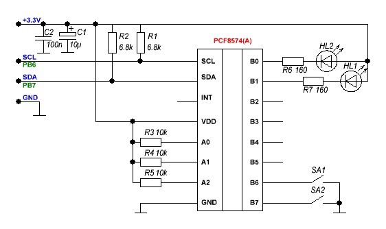
The address of the microcircuit is formed from the state of the pins A0, A1, A2 . For PCF8574, the address is 0100A0A1A2 . (For example, we have A0, A1, A2 have a high level, respectively, the address of our chip is 0b0100 111 = 0x27). For PCF8574A - 0111A0A1A2 , which with our connection scheme will give the address 0b0111 111 = 0x3F . If, say, A2 is connected to ground, then the address for PCF8574A will be 0x3B . Total for one bus i2c can simultaneously hang 16 chips, 8 PCF8574A and PCF8574.
Let's try to transfer something to initialize the i2c bus and transfer something to our PCF8574.
#define PCF8574A_ADDR 0x3F //c PCF8574 void I2C_PCF8574_WriteReg(unsigned char wData) { I2C1_Start(); // START I2C1_Write(PCF8574A_ADDR,&wData, 1, END_MODE_STOP); // 1 STOP } char PCF8574A_reg; // PCF8574 void main () { I2C1_Init_Advanced(400000, &_GPIO_MODULE_I2C1_PB67); // I2C delay_ms(25); // PCF8574A_reg.b0 = 0; // PCF8574A_reg.b1 = 1; // while (1) { delay_ms(500); PCF8574A_reg.b0 = ~PCF8574A_reg.b0; PCF8574A_reg.b1 = ~PCF8574A_reg.b1; // I2C_PCF8574_WriteReg (PCF8574A_reg); // PCF8574 } } We compile and run our program and see that our LEDs blink alternately.
I did not just connect the cathode LEDs to our PCF8574. The fact is that the microcircuit, when a logical 0 is applied to the output, honestly attracts its output to the ground, but when a logical 1 is applied, it connects it to the + supply through a current source of 100 μA. Ie "honest" logical 1 at the output does not get. And the LED from 100 μA does not light up. This is done in order to customize the PCF8574 input to the input without additional registers. We just write to the output register 1 (in fact, we set the state of the foot in Vdd) and we can simply short it to the ground. The current source will not “burn” the output stage of our I / O expander. If the leg is attracted to the earth, then the earth potential is on it, and logical 0 is read. If the leg is attracted to +, then the logical 1 is read. On the one hand, it is simple, but on the other hand, you should always remember about it while working with these microchips.

Let's try to read the state of the findings of our expander microcircuit.
#define PCF8574A_ADDR 0x3F //c PCF8574 void I2C_PCF8574_WriteReg(unsigned char wData) { I2C1_Start(); // START I2C1_Write(PCF8574A_ADDR, &wData, 1, END_MODE_STOP); // 1 STOP } void I2C_PCF8574_ReadReg(unsigned char rData) { I2C1_Start(); // START I2C1_Read(PCF8574A_ADDR, &rData, 1, END_MODE_STOP); // 1 STOP } char PCF8574A_reg; // PCF8574 char PCF8574A_out; // PCF8574 char lad_state; // void main () { I2C1_Init_Advanced(400000, &_GPIO_MODULE_I2C1_PB67); // I2C delay_ms(25); // PCF8574A_reg.b0 = 0; // PCF8574A_reg.b1 = 1; // PCF8574A_reg.b6 = 1; // 6 7 . PCF8574A_reg.b7 = 1; while (1) { delay_ms(100); I2C_PCF8574_WriteReg (PCF8574A_reg); // CF8574 I2C_PCF8574_ReadReg (PCF8574A_out); // CF8574 if (~PCF8574A_out.b6) PCF8574A_reg.b0 = ~PCF8574A_reg.b0; // 1 (6 CF8574 0, / ) if (~PCF8574A_out.b7) PCF8574A_reg.b1 = ~PCF8574A_reg.b1; // 2 2 } } Now by pressing the buttons we turn on or off our LED. The microcircuit has an INT pin. A pulse is formed on it every time the state of the outputs of our I / O expander changes. Having connected it to the external interrupt input of our MC (how to configure external interrupts and how to work with them, I will tell in one of the following articles).
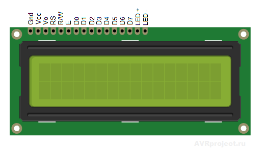
Let's use our port extender to connect a character display through it. There are a great many, but almost all of them are based on the HD44780 controller chip and its clones. For example, I used the LCD2004 display.
The datashit on it and the HD44780 controller can be easily found on the Internet. We connect our display to the RCF8574, and its, respectively, to our STM32.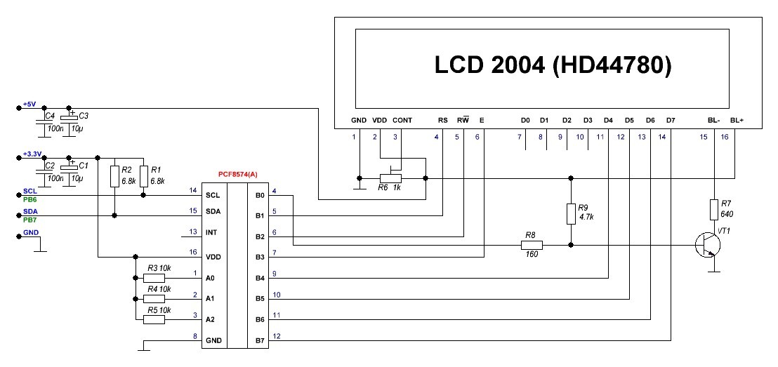
HD44780 uses a parallel gated interface. Data is transmitted over 8 (in one clock) or 4 (in 2 clock cycles) of the strobe pulse at pin E. (read by the display controller on the descending front, the transition from 1 to 0). The RS output indicates whether we send data to our display ( RS = 1 ) (the characters it should display, in fact, from ASCII codes) or commands ( RS = 0 ). RW indicates the direction of data transfer, write or read. Usually we write data to the display, therefore ( RW = 0 ). Resistor R6 controls the display contrast. Just connect the input contrast adjustment to the ground or power can not, otherwise you will not see anything. . VT1 is used to turn on and off the backlight display commands MK. MicroC has a library for working with such displays on a parallel interface, but usually it’s expensive to spend 8 feet on a display, so I almost always use the F8574 to work with such small screens. (If someone is interested, I will write an article about working with HD44780-based displays built into MicroC via a parallel interface.) The exchange protocol is not particularly complicated (we will use 4 data lines and transmit information in 2 cycles), the following shows it timing chart: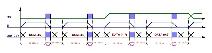
Before transferring data to our display, it must be initialized by passing service commands. (Described in the datasheet, here we give only the most used)
- 0x28 - communication with the indicator by 4 lines
- 0x0C - enable image output, disable cursor display
- 0x0E - enable image output, enable cursor display
- 0x01 - clear the indicator
- 0x08 - disable image output
- 0x06 - after the character is displayed , the cursor moves by 1 familiarity
Since we will need to work with this indicator quite often, we will create a plug-in library “i2c_lcd.h” . To do this, right click on the Header Files folder in the Project Maneger and select Add New File . Create our header file.
#define PCF8574A_ADDR 0x3F //c PCF8574 #define DB4 b4 // PCF8574 #define DB5 b5 #define DB6 b6 #define DB7 b7 #define EN b3 #define RW b2 #define RS b1 #define BL b0 // #define displenth 20 // static unsigned char BL_status; // (/) void lcd_I2C_Init(void); // PCF8574 void lcd_I2C_txt(char *pnt); // , - void lcd_I2C_int(int pnt); // , - void lcd_I2C_Goto(unsigned short row, unsigned short col); // , row - ( 1 2 4 ) col - ( 1 displenth)) void lcd_I2C_cls(); // void lcd_I2C_backlight (unsigned short int state); // ( 1 - 0 ) Now we will describe our functions, again go to the Project Maneger , right click on the Sources folder and select Add New File . Create the file "i2c_lcd.c" .
#include "i2c_lcd.h" // - char lcd_reg; // PCF8574 void I2C_PCF8574_WriteReg(unsigned char wData) // i2c PCF8574 { I2C1_Start(); I2C1_Write(PCF8574A_ADDR,&wData, 1, END_MODE_STOP); } void LCD_COMMAND (char com) // { lcd_reg = 0; // 0 lcd_reg.BL = BL_status.b0; // , lcd_reg.DB4 = com.b4; // 4 lcd_reg.DB5 = com.b5; lcd_reg.DB6 = com.b6; lcd_reg.DB7 = com.b7; lcd_reg.EN = 1; // . 1 I2C_PCF8574_WriteReg (lcd_reg); // PCF8574, delay_us (300); // lcd_reg.EN = 0; // 0, I2C_PCF8574_WriteReg (lcd_reg); delay_us (300); lcd_reg = 0; lcd_reg.BL = BL_status.b0; lcd_reg.DB4 = com.b0; // 4 lcd_reg.DB5 = com.b1; lcd_reg.DB6 = com.b2; lcd_reg.DB7 = com.b3; lcd_reg.EN = 1; I2C_PCF8574_WriteReg (lcd_reg); delay_us (300); lcd_reg.EN = 0; I2C_PCF8574_WriteReg (lcd_reg); delay_us (300); } void LCD_CHAR (unsigned char com) // (ASCII ) { lcd_reg = 0; lcd_reg.BL = BL_status.b0; lcd_reg.EN = 1; lcd_reg.RS = 1; // 1 RS lcd_reg.DB4 = com.b4; // 4 lcd_reg.DB5 = com.b5; lcd_reg.DB6 = com.b6; lcd_reg.DB7 = com.b7; I2C_PCF8574_WriteReg (lcd_reg); delay_us (300); lcd_reg.EN = 0; // . 0, I2C_PCF8574_WriteReg (lcd_reg); delay_us (300); lcd_reg = 0; lcd_reg.BL = BL_status.b0; lcd_reg.EN = 1; lcd_reg.RS = 1; lcd_reg.DB4 = com.b0; // 4 lcd_reg.DB5 = com.b1; lcd_reg.DB6 = com.b2; lcd_reg.DB7 = com.b3; I2C_PCF8574_WriteReg (lcd_reg); delay_us (300); lcd_reg.EN = 0; I2C_PCF8574_WriteReg (lcd_reg); delay_us (300); } void lcd_I2C_Init(void) { I2C1_Init_Advanced(400000, &_GPIO_MODULE_I2C1_PB67); // I2c delay_ms(200); lcd_Command(0x28); // 4 delay_ms (5); lcd_Command(0x08); // delay_ms (5); lcd_Command(0x01); // delay_ms (5); lcd_Command(0x06); // delay_ms (5); lcd_Command(0x0C); // delay_ms (25); } void lcd_I2C_txt(char *pnt) // { unsigned short int i; // char tmp_str[displenth + 1]; // , 1 , v NULL ASCII 0x00 strncpy(tmp_str, pnt, displenth); // displenth for (i=0; i<displenth; i++) { if (tmp_str[i] == 0) break; // NULL , і LCD_CHAR(tmp_str[i]); // } } void lcd_I2C_int(int pnt) // { char tmp_str[8]; // unsigned short i, j; IntToStr(pnt,tmp_str); // , 6 + NULL while (tmp_str[0]==32) { for (i=0; i<7; i++) { tmp_str[i]=tmp_str[i+1]; // (ASCII 32) tmp_str[6-j]=0; } j++; } lcd_I2C_txt (tmp_str); // } void lcd_I2C_Goto(unsigned short row, unsigned short col) // { col--; // 0, 1 switch (row) { case 1: lcd_Command(0x80 + col); // break; case 2: lcd_Command(0x80 + col + 0x40); break; case 3: lcd_Command(0x80 + col + 0x14); break; case 4: lcd_Command(0x80 + col + 0x54); break; } } void lcd_I2C_cls() // { lcd_Command(0x01); delay_ms (5); } void lcd_I2C_backlight (unsigned short int state) // { lcd_reg = 0; BL_status.b0 = state.b0; // , lcd_reg.BL = state.b0; I2C_PCF8574_WriteReg (lcd_reg); delay_ms (1); } Now connect the newly created library to the file with our main function:
#include "i2c_lcd.h" // - unsigned int i; // void main() { lcd_I2C_Init(); // lcd_I2C_backlight (1); // lcd_I2C_txt ("Hellow habrahabr"); // while (1) { delay_ms(1000); lcd_I2C_Goto (2,1); // 1 2 lcd_i2c_int (i); // i++; // } } If everything is correctly assembled, then we should see a text on the indicator and an incremented counter every second. In general, nothing complicated :)
In the next article, we will continue to deal with the i2c protocol and devices working with it. Consider working with EEPROM 24XX memory and MPU6050 accelerometer / gyroscope.
Source: https://habr.com/ru/post/322184/
All Articles