Wiring diagrams in Autocad using .NET
After graduation, I came to work at an engineering company as an electrical engineer. All calculations were carried out in Excel, after which it was necessary to draw charts based on calculated data, which took a lot of time. In addition, errors were accumulating when transferring data from Excel to Autocad. When you change the source data, you had to correct the calculations, and then the scheme. In general, a bunch of useless work that took a lot of time.
It is good that AutoCAD provides ample opportunities for developers in the field of automation of the design process and helps to save hundreds and thousands of hours of work.
A special plugin based on .NET was developed, which exported data from Excel and created electrical circuits in AutoCAD.
The principle of operation of the plugin is quite simple. The working DWG file contains blocks-elements of the circuits with attributes that contain information about the installed capacity, rated current, etc. The plugin reads data from the Excel calculation table and builds a block diagram, filling the attributes with numbers from the calculation table.
Recently, I began to ask questions with requests to add something, add, change. But unfortunately, there is not enough time for revision, and every engineer has his own wishes. In this regard, I post the source:
')
→ https://github.com/NabiyevTR/SingleDiagram
I hope that the plugin will help save time for design engineers and improve the quality of documentation.
→ Download plugin
Of course, this plugin can not solve all the problems. Unfortunately, there are no universal solutions. In this section, I will try to answer questions that you may have while working with this program.
It is good that AutoCAD provides ample opportunities for developers in the field of automation of the design process and helps to save hundreds and thousands of hours of work.
A special plugin based on .NET was developed, which exported data from Excel and created electrical circuits in AutoCAD.
The principle of operation of the plugin is quite simple. The working DWG file contains blocks-elements of the circuits with attributes that contain information about the installed capacity, rated current, etc. The plugin reads data from the Excel calculation table and builds a block diagram, filling the attributes with numbers from the calculation table.
Recently, I began to ask questions with requests to add something, add, change. But unfortunately, there is not enough time for revision, and every engineer has his own wishes. In this regard, I post the source:
')
→ https://github.com/NabiyevTR/SingleDiagram
I hope that the plugin will help save time for design engineers and improve the quality of documentation.
Instructions for working with the plugin
→ Download plugin
System requirements
- Autodesk AutoCAD 2015
- Microsoft Office Excel 2010 and later
Archive composition
- The plugin files are located in the Program Files folder. Here you need the OneLine3.dll library file . The remaining files are auxiliary, needed for the plugin to work.
- The file SHIELD.xslm contains a calculation table, on the basis of which a single-line diagram is built
- File SCHEME.dwg is a file that contains the necessary elements for creating a single-line diagram. This is where we will load the plugin.
- The file SLD_Buttons.cuix is an adaptation file. In order not to write commands on the command line, you can load it into AutoCAD and use the buttons.
Work with plugin
- Unzip the archive on a local disk. If the plugin is hosted on the server, AutoCAD will not allow it to run.
- Launch AutoCAD and open the SCHEME.dwg file.
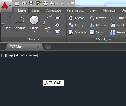
- Now you need to load the plugin in AutoCAD. At the command prompt, enter _NETLOAD .
- In the window that opens, specify the path to the OneLine3.dll file.
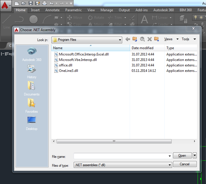
- AutoCAD will display a warning that the file being downloaded is outside the safe location. Click the Download button.

- Now that the plugin is loaded, you need to run it. Type _DSLD in the command line.

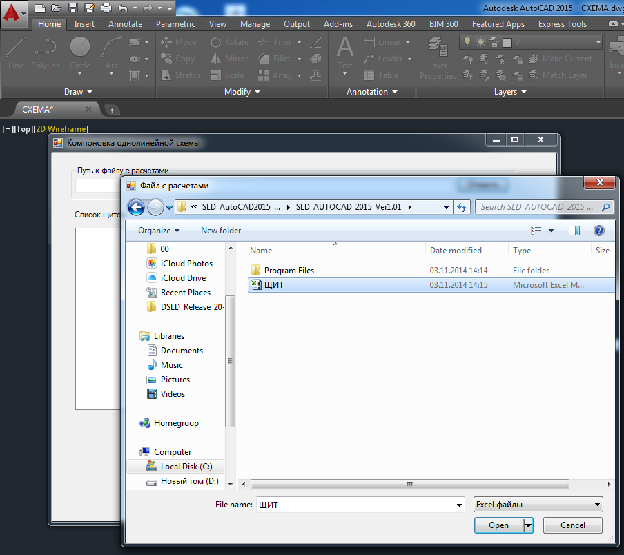
- A window has appeared. Now you need to click the Open button.

- In the window that opens, specify the path to the file with the calculations SHIELD.xslm .
- Loaded data from the table. The left column shows the sheets from the file SHIELD.xslm . Select a shield (s) and transfer them to the second column by pressing button 1 . Then click the button Draw .

- But the result of our work.

Questions that may arise when working with the program
Of course, this plugin can not solve all the problems. Unfortunately, there are no universal solutions. In this section, I will try to answer questions that you may have while working with this program.
I downloaded the plugin, but nothing happens when I invoke the command. The command line says: Failed to load the assembly. Error Details: System.IO.FileLoadException: Failed to load file or assembly ...
AutoCAD 2015 and later versions do not allow libraries loaded via the Internet to be connected. To avoid this, you need to make a change to the acad.exe.config file, add the line:
It should turn out like this:
<loadFromRemoteSources enabled="true"/> It should turn out like this:
<configuration> <startup useLegacyV2RuntimeActivationPolicy="true"> <supportedRuntime version="v4.0"/> </startup> <!--All assemblies in AutoCAD are fully trusted so there's no point generating publisher evidence--> <runtime> <generatePublisherEvidence enabled="false"/> <loadFromRemoteSources enabled="true"/> </runtime> </configuration> I need to make changes to the schemes created earlier. How to do it?
There are two ways to make changes. The first is to make changes in the calculation file and generate the schema again using the plugin.
The second way is to make changes in the drawing itself. This can be done through Properties , highlighting the necessary element.

You can change the data through the Attribute Editor by double-clicking the left mouse button on the edited block.

The second way is to make changes in the drawing itself. This can be done through Properties , highlighting the necessary element.
You can change the data through the Attribute Editor by double-clicking the left mouse button on the edited block.
How to replace a circuit breaker with a differential circuit breaker?
All blocks are made dynamic. Just change the block type.

How to change the font?
Open and change the style SLD_Style . After that, it is advisable to execute the _REGEN and _REGENALL commands .
I try to partition objects with the _EXPLODE command, but all data is lost.
Use the _BURST command.
I do not need to show the brand of the switch. How to make it not displayed?
Select the block and open it in the block editor.
Remove unnecessary attribute.
Close the block editor, saving changes.
Enter _ATTSYNC and select an editable block. After synchronization, the deleted attribute should disappear.
Similarly, you can delete and move other attributes.
Remove unnecessary attribute.
Close the block editor, saving changes.
Enter _ATTSYNC and select an editable block. After synchronization, the deleted attribute should disappear.
Similarly, you can delete and move other attributes.
Source: https://habr.com/ru/post/322042/
All Articles