DALI light control with Arduino
About the DALI protocol
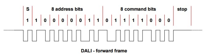
DALI (Digital Addressable Lighting Interface) - a protocol designed to control lighting devices. The protocol was developed by the Austrian company Tridonic and is based on Manchester coding: each data bit is encoded by a difference from a low signal to a high one or vice versa.
DALI network consists of a controller and lighting devices connected to it. Data transmission goes at 1200bit / s. The voltage for a logical unit is 16 ± 6.5V, and for a logical zero 0 ± 4.5V. The DALI bus is always at a voltage of 16V, otherwise all the lighting devices connected to the bus go into emergency mode and turn on. Bus power is provided by the controller. Up to 64 luminaires can be connected to one bus. Devices can be combined into 16 groups and set up to 16 lighting scenes. The brightness of each light is adjustable from 0 to 254.
The message from the controller to the lighting fixture consists of 16 bits and one start bit. A message can be addressed to a single lamp, a group of lamps or to be broadcast. Some commands must be transmitted twice at intervals of not more than 100ms. For certain commands, such as a request for the current brightness or a request for a device type, the lighting device sends a response message.
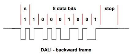
The message from the lighting device to the controller consists of 8 bits and one start bit.
A list of commands can be found here .
Initialization of new fixtures
Before starting work, each luminaire must be assigned an address from 1 to 63 (short address). New luminaires do not usually have a short address, so it’s impossible to manage a specific luminaire. These lights only respond to broadcast commands.
In order to assign a short address to the lamp you need to initialize it. Each lamp has a random address consisting of 24 bits (3 times 8 bits). A 24-bit address can take values from 1 to 16777216. The probability of connecting luminaires with identical addresses is minimal and is one case out of 1 out of 266,144.
The initialization process is as follows:
- The INITIALISE broadcast command (0b1010010100000000) is transmitted twice from the controller at intervals of not more than 100ms, which puts all the lights into initialization mode;
- the broadcast command RANDOMISE (0b1010011100000000) is transmitted twice from the controller with an interval of not more than 100ms, after which all the lamps assign a new random address to themselves;
- the value of a random address (24 bits) is transmitted from the controller by three messages of 8 bits (0b10110001HHHHHHHH, 0b10110011MMMMMMMMM, 0b10110101LLLLLLLLLLLL);
- the controller transmits the COMPARE broadcast command (0b1010100100000000);
- if the controller captures the response message, then there are lamps with lower addresses; thus, the requested address is reduced until the luminaires stop responding;
- if a response from the luminaire has not been received, the address is increased by one unit and thus the luminaire with the smallest random address is determined;
- after determining the address of the lamp, the controller sets the lamp a short address (0b10110111AAAAAAAA) and sends the command WITHRAW (0b101010110000000000), which excludes the lamp from the search process;
- then the controller proceeds to search for the next luminaire with a large random address;
- after the initialization process is completed, the controller sends the TERMINATE command (0b1010000100000000), and the luminaires exit the initialization mode.
DALI and ARDUINO
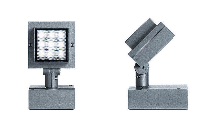
To control the lamp, I used the ARDUINO NANO, a 12V power supply unit, resistors, LEDs, a transistor and an ERCO Grasshopper lamp. The scheme is quite simple.

ERCO Grasshopper is designed to illuminate the facades of buildings and architectural monuments. I had a RGB fixture with a DALI TRIDONIC driver. This luminaire has 3 addresses (RED, GREEN, BLUE).
Library DALI can be downloaded here .
Customization
void setup() { Serial.begin(74880); /* . */ dali.setupTransmit(3); /* . (12 2,1) 0. 4,5, 3,8. */ dali.setupAnalogReceive(0); /* : - ; - . */ dali.busTest(); /* , -COM false - ; true - . */ dali.msgMode = true; } Basic commands
/* DALI , : cmd1 - ; cmd2 - . */ dali.transmit(cmd1, cmd2) /* */ uint8_t response = dali.receive() /* */ bool response = dali.getResponse() /* . */ dali.scanShortAdd() /* . */ dali.initialisation(); Usage example
Below is an example of using the library. Combining the brightness of different channels of the lamp, we get different colors.
#include <Dali.h> const int DALI_TX = 3; const int DALI_RX_A = 0; #define BROADCAST_C 0b11111111 #define ON_C 0b00000101 void setup() { Serial.begin(74880); // dali.setupTransmit(DALI_TX); // dali.setupAnalogReceive(DALI_RX_A); // dali.busTest(); // dali.msgMode = true; sinus(); } void sinus () { // uint8_t lf_1_add = 0; uint8_t lf_2_add = 1; uint8_t lf_3_add = 2; // uint8_t lf_1; uint8_t lf_2; uint8_t lf_3; // uint8_t i; while (Serial.available() == 0) { for (i = 0; i < 360; i ++) { // if (Serial.available() != 0) { dali.transmit(BROADCAST_C, ON_C); break; } // lf_1 = (int) abs(254 * sin(i * 3.14 / 180)); lf_2 = (int) abs(254 * sin(i * 3.14 / 180 + 2 * 3.14 / 3)); lf_3 = (int) abs(254 * sin(i * 3.14 / 180 + 1 * 3.14 / 3)); // dali.transmit(lf_1_add << 1, lf_1); delay(5); dali.transmit(lf_2_add << 1, lf_2); delay(5); dali.transmit(lf_3_add << 1, lf_3); delay(5); delay(20); } } } void loop() { }; Literature
')
Source: https://habr.com/ru/post/321888/
All Articles