Exceptions in Windows x64. How it works. Part 1
We have previously discussed the application of the exception handling mechanism outside of the Windows environment . Now we take a closer look at how this works in Windows x64. The material will be described sequentially, starting with the basics. Therefore, much may be familiar to you, and in this case, such moments can simply be missed.
The mechanism implementation is located in the git repository exceptions folder at this address .
Any function has a prologue, body and epilogue. More detail on the prologue and the epilogue, because there are no questions with the body itself, because it is for him that everything is started.
In the function prolog is the code that performs the preliminary actions that are necessary before the function body works. They include the preservation of general purpose registers, the values of which could be set by the calling function, the allocation of memory in the stack for local variables of the function, the setting of a frame pointer and the saving of XMM registers of the processor. The prolog has strict rules regarding the actions that he can perform and their sequence. First, if necessary, the prolog saves the first 4 parameters in the register parameters area (more details about this area and everything connected with it will be written in section 3), then general registers are pushed, memory is allocated in the stack, the frame pointer is set optionally functions and saved XMM registers of the processor. Any of the listed actions may be missing, but the described order of execution is strictly observed. Such strict rules allow you to analyze the actions of the epilogue by its program code, which will be discussed in more detail below. Figure 1 illustrates the prolog of a function that saves the first 4 parameters passed, saves three general-purpose registers, allocates memory, and saves the XMM register.
')

Picture 1
It should also be noted that the general purpose registers can be saved after memory allocation in the stack (as well as after setting the function frame, if any), but in this case it is performed not by pushing, but by regular writing to the memory, as this is shown in the previous example. It should also be noted that in very rare cases, it is allowed to allocate 8 bytes in a stack before pushing general registers into the function prolog. Such a prolog is most typical for exception handlers for which the processor does not push an error code onto the stack, and this 8-byte allocation allows it to be simulated.
The stored general purpose registers, the allocated memory in the stack, and the stored XMM registers all together form the so-called function frame (frame), which each function called has. Below, in Figure 2, a stack consisting of three frames is presented. The first frame is the frame of the function in the context of which the exception occurred. For brevity, the figure shows only that area of the frame, which is pushed by the processor at the time of the exception. The second frame is an exception handler frame, which consists of an empty error code (even if in this example the exception was caused by dividing by zero, which does not push the error code onto the stack, and our handler, like the Windows handler, forms empty code for consistency) saved registers RAX, RCX, RDX, R8, R9, R10, R11, saved registers XMM0, XMM1, XMM2, XMM3, XMM4, XMM5 and return addresses. These saved general purpose registers and XMM registers are listed for a reason; we’ll talk about this in section 3. The third frame is the function frame that the exception handler called. Its frame consists of saved registers RBP, RBX, XMM and allocated space for local variables of the function. The arrow indicates the direction of growth of the stack.
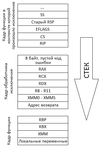
Figure 2
The function may have a frame pointer. In this case, the frame is accessed via this pointer. First of all, this is necessary in cases where during the execution of a function, the allocated space in the stack can be dynamically changed (ie, memory allocation in the stack is additionally performed in the body of the function, and not in the prolog). And since this entails a change in the stack pointer, it will not point to a function frame. If the function does not have a frame pointer, it cannot dynamically allocate memory in the stack, therefore, the stack pointer is static and is also the function frame pointer. Figure 3 illustrates such a prologue. After saving all registers and allocating memory, a function is called in the function body, which in RAX returns the size of the structure, this size is allocated in the stack, and then the stack pointer is used as a pointer to the buffer into which data is read.
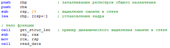
Figure 3
If the prolog selects an area on the stack that is larger than one page (ie, more than 4Kb), then it is likely that such allocation will cover more than one virtual memory page and, therefore, such allocation should be checked before it is actually executed. To this end, the function prologue calls a special function that performs this check. The name of the function is _chkstk. Also, this function does not change the values of the registers in which parameters are transmitted (these registers will be described in detail in section 3). Figure 4 shows an example of the function prologue, which allocates 4K of memory in the stack.

Figure 4
The epilogue performs the opposite actions in relation to the prologue: it restores XMM registers and general-purpose registers that were saved after memory allocation in the stack, releases memory in the stack (and if the frame pointer was used, then dynamically allocated, also) pushes the general-purpose registers , returns to the calling function or transfers control to the beginning of the current function or another function. Figure 5 shows the epilogue corresponding to the prologue from the example in Figure 1. From the figure you can see that actions opposite to the prologue are performed. Also note that the transferred parameters are not restored, an explanation for this can be found in section 3.

Figure 5
The epilogue, like the prologue, has strict rules regarding the processor instructions used. If the function did not use the frame pointer, then the memory in the stack, as reflected in the previous example, is released using add rsp, an instruction constant , and if it is used, it is released by lea rsp, [frame pointer + constant] . Then follow the instructions to push the general-purpose registers out of the stack, the return instruction or the instruction to unconditionally switch to another function or to the beginning of the current function. Figure 6 shows the epilogue corresponding to the prologue from the example in Figure 3. Note that instead of the ret instruction, jmp is used to call another function.

Figure 6
As for the transition instructions, only a limited set of them are allowed. Despite the fact that the epilogue first restores the XMM registers and general purpose registers, the beginning of the epilogue, when unrolling, it is considered to release memory from the stack via add rsp, constant or lea rsp, [frame pointer + constant] instruction. The explanation will be given in the third part of this article, and the first information about the promotion will be given in the next part of this article.
All of the above regarding the epilog is valid for functions whose version of the UNWIND_INFO structure is equal to 1 (more detail about UNWIND_INFO will be written in the next part of this article). Whether the processor performed the epilog function at the time of the interruption / exclusion is determined by the code of the function itself. This is possible because, as has been repeatedly noted, a strict procedure has been imposed on the actions of the prologue and epilogue, and the epilogue also has limitations regarding the processor instructions it uses. UNWIND_INFO version 2 structures can also describe the location of the function epilogue. We will talk about this in more detail in the next part of this article, it’s worth mentioning that the epilogues of functions described by UNWIND_INFO version 2 structures can, after pushing general registers, free 8 bytes from the stack, which we already talked about during the prologue discussion. The same release of 8 bytes from the stack after the ejection of general-purpose registers is not expected from the epilogues of functions described by UNWIND_INFO version 1 structures. Consequently, in existing Windows implementations, checking for the availability of this release in the program code of the epilog functions described by UNWIND_INFO version 1 structures is not performed. In the attached to the article implementation of this mechanism, such verification is also not performed.
At least the function has one epilogue.
There are two types of functions: frame functions (frame functions) and simple functions (leaf functions).
Frame functions are those that have their frame on the stack and they have no restrictions on the part of their actions. They can call other functions, allocate memory in the stack, save and use any processor registers. If the function does not call other functions, then its stack has no alignment constraints; if it calls, the stack must be aligned on a 16-byte boundary. Also, the personnel function has corresponding records for the promotion of its frame (we will discuss this in more detail in the next part of this article).
Simple functions are those functions that do not have their frame on the stack, so they cannot perform all that personnel functions, including using any processor registers. Since a simple function cannot call other functions, it does not align its stack. Also, a simple function has no promotion entries, since she has no frame.
The first 4 parameters are passed to the function through registers. If there are more, the rest are passed through the stack. Also, the calling function for the first 4 parameters allocates an area in the stack, called the register parameters area or home location. The called function can use this area to save parameters, as the prologue did in Figure 1, or for any other purpose. Even if the function takes less than 4 parameters or does not accept them at all, the region of the register parameters is always allocated in the stack. The parameters passed through the stack are located in an area called the stack parameters area. This area, in contrast to the area of register parameters, may be absent, and its size is equal to the size of all parameters that it includes. One parameter in the field of register and stack parameters always takes 8 bytes. If the parameter size is greater than 8, then a pointer to it is passed instead. If the parameter size is less than 8 bytes, then the highest unused bytes in the corresponding areas are ignored. The figure 7 below shows the calls of two functions, one of which takes 6 parameters, and the other 1, to the left and to the right of the arrow of the direction of growth of the stack, respectively.
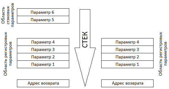
Figure 7
At the bottom of the stack there is always a register parameters area, above which follows the stack parameters area. In the case of a function call, the return address will be located immediately below the register parameters area. In section 2, it was mentioned that if a function calls other functions, then its stack must be aligned with a 16-byte boundary. On this 16-byte border, the region of register parameters always begins.
The first 4 parameters are transmitted through the registers RCX, RDX, R8 and R9, if it is an integer or a custom type, the size of which is 1, 2, 4 or 8 bytes. Otherwise, a pointer is passed to the corresponding parameter. For strings and arrays, their pointer is always passed. If the parameter is a floating point number, then XMM0, XMM1, XMM2, XMM3 registers are used to transfer it, provided that the parameter size does not exceed 8 bytes, otherwise a pointer to it is passed. If a pointer to a parameter is passed instead of the parameter itself, the parameter itself is placed in temporary memory on a 16-byte boundary. Figure 8 shows examples of passing parameters to functions.
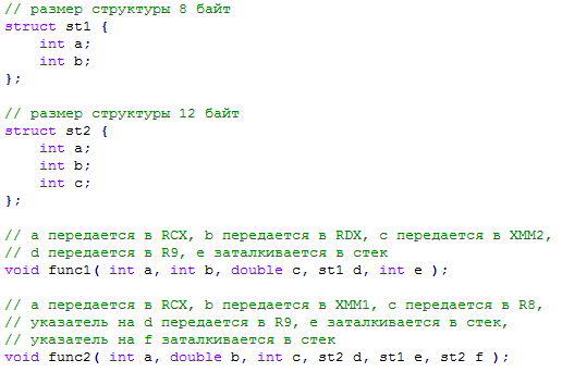
Figure 8
When XMM is used to pass a parameter, the XMM register that corresponds to one of the RCX, RDX, R8 or R9 registers is used. For example, in Figure 8, parameter 3 of the function func1 carries a floating point number, in which case the XMM2 register will be used. If this parameter were an integer, as in the function func2, then the register R8 would be used.
The function returns the result via RAX or XMM0. Floating-point numbers and vectors up to 16 bytes (for example, _m128) are returned in XMM0. Integers and custom types that are 1, 2, 4, or 8 bytes in size are returned to RAX. If the return value is less than 8 bytes, then the highest unused bytes are undefined. In all other cases, the first parameter of the function is a pointer to the area where the value is returned, and in RAX this pointer is returned. It should also be noted that in this case, the transmitted parameters are shifted by one parameter to the right, i.e. the first parameter will not be transmitted in RCX, but in the RDX register, and the 4th parameter will be transmitted not in R9, but in the stack. Figure 9 shows examples of the return result.
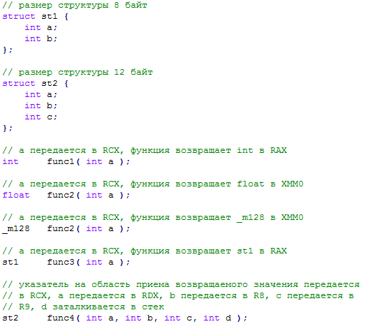
Figure 9
C ++ compiler imposes additional restrictions on user types. If the result is returned by a non-static function (which is a member of a class, structure, etc.), or the type itself has a constructor, a destructor, an assignment operator, private or protected non-static members, non-static members such as reference, an inherited parent, virtual functions or members, containing any of the above, the result is not returned in RAX, but in the memory area, the pointer to which is passed in the first parameter.
The registers RBX, RBP, RDI, RSI, RSP, R12, R13, R14 and R15 are considered permanent (nonvolatile or callee-saved), i.e. the called function must save them before use and restore before returning, and the calling function can rely on the values of these registers after calling the functions.
The registers RAX, RCX, RDX, R8, R9, R10 and R11 are considered non-permanent (volatile or caller-saved), i.e. the called function should not save them before use, and the calling function should not rely on the values of these registers after calling the functions. For this reason, the epilogue shown in Figure 5, corresponding to the prologue from the example in Figure 1, does not restore the registers RCX, RDX, R8, R9 saved by the prologue. And for the same reason, the exception handler mentioned in section 1 only stores them, since these registers are not restored by callable functions before returning.
Like general-purpose registers, XMM0 - XMM5 registers are considered non-permanent, and XMM6 registers - XMM15 are permanent.
In this part of the article we have dealt with the basic concepts, definitions and processes, which, at first glance, although not explicitly related to the topic under discussion, but, nevertheless, knowledge and understanding of which is necessary for consideration of the subsequent material, since this is the basis on which the mechanism under discussion is based. The continuation of the article will be devoted to the description of those areas of the PE image that are involved in the process of exception handling.
The mechanism implementation is located in the git repository exceptions folder at this address .
1. Function, its prologue, body, epilogue and function frame
Any function has a prologue, body and epilogue. More detail on the prologue and the epilogue, because there are no questions with the body itself, because it is for him that everything is started.
In the function prolog is the code that performs the preliminary actions that are necessary before the function body works. They include the preservation of general purpose registers, the values of which could be set by the calling function, the allocation of memory in the stack for local variables of the function, the setting of a frame pointer and the saving of XMM registers of the processor. The prolog has strict rules regarding the actions that he can perform and their sequence. First, if necessary, the prolog saves the first 4 parameters in the register parameters area (more details about this area and everything connected with it will be written in section 3), then general registers are pushed, memory is allocated in the stack, the frame pointer is set optionally functions and saved XMM registers of the processor. Any of the listed actions may be missing, but the described order of execution is strictly observed. Such strict rules allow you to analyze the actions of the epilogue by its program code, which will be discussed in more detail below. Figure 1 illustrates the prolog of a function that saves the first 4 parameters passed, saves three general-purpose registers, allocates memory, and saves the XMM register.
')
Picture 1
It should also be noted that the general purpose registers can be saved after memory allocation in the stack (as well as after setting the function frame, if any), but in this case it is performed not by pushing, but by regular writing to the memory, as this is shown in the previous example. It should also be noted that in very rare cases, it is allowed to allocate 8 bytes in a stack before pushing general registers into the function prolog. Such a prolog is most typical for exception handlers for which the processor does not push an error code onto the stack, and this 8-byte allocation allows it to be simulated.
The stored general purpose registers, the allocated memory in the stack, and the stored XMM registers all together form the so-called function frame (frame), which each function called has. Below, in Figure 2, a stack consisting of three frames is presented. The first frame is the frame of the function in the context of which the exception occurred. For brevity, the figure shows only that area of the frame, which is pushed by the processor at the time of the exception. The second frame is an exception handler frame, which consists of an empty error code (even if in this example the exception was caused by dividing by zero, which does not push the error code onto the stack, and our handler, like the Windows handler, forms empty code for consistency) saved registers RAX, RCX, RDX, R8, R9, R10, R11, saved registers XMM0, XMM1, XMM2, XMM3, XMM4, XMM5 and return addresses. These saved general purpose registers and XMM registers are listed for a reason; we’ll talk about this in section 3. The third frame is the function frame that the exception handler called. Its frame consists of saved registers RBP, RBX, XMM and allocated space for local variables of the function. The arrow indicates the direction of growth of the stack.
Figure 2
The function may have a frame pointer. In this case, the frame is accessed via this pointer. First of all, this is necessary in cases where during the execution of a function, the allocated space in the stack can be dynamically changed (ie, memory allocation in the stack is additionally performed in the body of the function, and not in the prolog). And since this entails a change in the stack pointer, it will not point to a function frame. If the function does not have a frame pointer, it cannot dynamically allocate memory in the stack, therefore, the stack pointer is static and is also the function frame pointer. Figure 3 illustrates such a prologue. After saving all registers and allocating memory, a function is called in the function body, which in RAX returns the size of the structure, this size is allocated in the stack, and then the stack pointer is used as a pointer to the buffer into which data is read.
Figure 3
If the prolog selects an area on the stack that is larger than one page (ie, more than 4Kb), then it is likely that such allocation will cover more than one virtual memory page and, therefore, such allocation should be checked before it is actually executed. To this end, the function prologue calls a special function that performs this check. The name of the function is _chkstk. Also, this function does not change the values of the registers in which parameters are transmitted (these registers will be described in detail in section 3). Figure 4 shows an example of the function prologue, which allocates 4K of memory in the stack.
Figure 4
The epilogue performs the opposite actions in relation to the prologue: it restores XMM registers and general-purpose registers that were saved after memory allocation in the stack, releases memory in the stack (and if the frame pointer was used, then dynamically allocated, also) pushes the general-purpose registers , returns to the calling function or transfers control to the beginning of the current function or another function. Figure 5 shows the epilogue corresponding to the prologue from the example in Figure 1. From the figure you can see that actions opposite to the prologue are performed. Also note that the transferred parameters are not restored, an explanation for this can be found in section 3.
Figure 5
The epilogue, like the prologue, has strict rules regarding the processor instructions used. If the function did not use the frame pointer, then the memory in the stack, as reflected in the previous example, is released using add rsp, an instruction constant , and if it is used, it is released by lea rsp, [frame pointer + constant] . Then follow the instructions to push the general-purpose registers out of the stack, the return instruction or the instruction to unconditionally switch to another function or to the beginning of the current function. Figure 6 shows the epilogue corresponding to the prologue from the example in Figure 3. Note that instead of the ret instruction, jmp is used to call another function.
Figure 6
As for the transition instructions, only a limited set of them are allowed. Despite the fact that the epilogue first restores the XMM registers and general purpose registers, the beginning of the epilogue, when unrolling, it is considered to release memory from the stack via add rsp, constant or lea rsp, [frame pointer + constant] instruction. The explanation will be given in the third part of this article, and the first information about the promotion will be given in the next part of this article.
All of the above regarding the epilog is valid for functions whose version of the UNWIND_INFO structure is equal to 1 (more detail about UNWIND_INFO will be written in the next part of this article). Whether the processor performed the epilog function at the time of the interruption / exclusion is determined by the code of the function itself. This is possible because, as has been repeatedly noted, a strict procedure has been imposed on the actions of the prologue and epilogue, and the epilogue also has limitations regarding the processor instructions it uses. UNWIND_INFO version 2 structures can also describe the location of the function epilogue. We will talk about this in more detail in the next part of this article, it’s worth mentioning that the epilogues of functions described by UNWIND_INFO version 2 structures can, after pushing general registers, free 8 bytes from the stack, which we already talked about during the prologue discussion. The same release of 8 bytes from the stack after the ejection of general-purpose registers is not expected from the epilogues of functions described by UNWIND_INFO version 1 structures. Consequently, in existing Windows implementations, checking for the availability of this release in the program code of the epilog functions described by UNWIND_INFO version 1 structures is not performed. In the attached to the article implementation of this mechanism, such verification is also not performed.
At least the function has one epilogue.
2. Types of functions
There are two types of functions: frame functions (frame functions) and simple functions (leaf functions).
Frame functions are those that have their frame on the stack and they have no restrictions on the part of their actions. They can call other functions, allocate memory in the stack, save and use any processor registers. If the function does not call other functions, then its stack has no alignment constraints; if it calls, the stack must be aligned on a 16-byte boundary. Also, the personnel function has corresponding records for the promotion of its frame (we will discuss this in more detail in the next part of this article).
Simple functions are those functions that do not have their frame on the stack, so they cannot perform all that personnel functions, including using any processor registers. Since a simple function cannot call other functions, it does not align its stack. Also, a simple function has no promotion entries, since she has no frame.
3. Call Agreement
The first 4 parameters are passed to the function through registers. If there are more, the rest are passed through the stack. Also, the calling function for the first 4 parameters allocates an area in the stack, called the register parameters area or home location. The called function can use this area to save parameters, as the prologue did in Figure 1, or for any other purpose. Even if the function takes less than 4 parameters or does not accept them at all, the region of the register parameters is always allocated in the stack. The parameters passed through the stack are located in an area called the stack parameters area. This area, in contrast to the area of register parameters, may be absent, and its size is equal to the size of all parameters that it includes. One parameter in the field of register and stack parameters always takes 8 bytes. If the parameter size is greater than 8, then a pointer to it is passed instead. If the parameter size is less than 8 bytes, then the highest unused bytes in the corresponding areas are ignored. The figure 7 below shows the calls of two functions, one of which takes 6 parameters, and the other 1, to the left and to the right of the arrow of the direction of growth of the stack, respectively.
Figure 7
At the bottom of the stack there is always a register parameters area, above which follows the stack parameters area. In the case of a function call, the return address will be located immediately below the register parameters area. In section 2, it was mentioned that if a function calls other functions, then its stack must be aligned with a 16-byte boundary. On this 16-byte border, the region of register parameters always begins.
The first 4 parameters are transmitted through the registers RCX, RDX, R8 and R9, if it is an integer or a custom type, the size of which is 1, 2, 4 or 8 bytes. Otherwise, a pointer is passed to the corresponding parameter. For strings and arrays, their pointer is always passed. If the parameter is a floating point number, then XMM0, XMM1, XMM2, XMM3 registers are used to transfer it, provided that the parameter size does not exceed 8 bytes, otherwise a pointer to it is passed. If a pointer to a parameter is passed instead of the parameter itself, the parameter itself is placed in temporary memory on a 16-byte boundary. Figure 8 shows examples of passing parameters to functions.
Figure 8
When XMM is used to pass a parameter, the XMM register that corresponds to one of the RCX, RDX, R8 or R9 registers is used. For example, in Figure 8, parameter 3 of the function func1 carries a floating point number, in which case the XMM2 register will be used. If this parameter were an integer, as in the function func2, then the register R8 would be used.
The function returns the result via RAX or XMM0. Floating-point numbers and vectors up to 16 bytes (for example, _m128) are returned in XMM0. Integers and custom types that are 1, 2, 4, or 8 bytes in size are returned to RAX. If the return value is less than 8 bytes, then the highest unused bytes are undefined. In all other cases, the first parameter of the function is a pointer to the area where the value is returned, and in RAX this pointer is returned. It should also be noted that in this case, the transmitted parameters are shifted by one parameter to the right, i.e. the first parameter will not be transmitted in RCX, but in the RDX register, and the 4th parameter will be transmitted not in R9, but in the stack. Figure 9 shows examples of the return result.
Figure 9
C ++ compiler imposes additional restrictions on user types. If the result is returned by a non-static function (which is a member of a class, structure, etc.), or the type itself has a constructor, a destructor, an assignment operator, private or protected non-static members, non-static members such as reference, an inherited parent, virtual functions or members, containing any of the above, the result is not returned in RAX, but in the memory area, the pointer to which is passed in the first parameter.
The registers RBX, RBP, RDI, RSI, RSP, R12, R13, R14 and R15 are considered permanent (nonvolatile or callee-saved), i.e. the called function must save them before use and restore before returning, and the calling function can rely on the values of these registers after calling the functions.
The registers RAX, RCX, RDX, R8, R9, R10 and R11 are considered non-permanent (volatile or caller-saved), i.e. the called function should not save them before use, and the calling function should not rely on the values of these registers after calling the functions. For this reason, the epilogue shown in Figure 5, corresponding to the prologue from the example in Figure 1, does not restore the registers RCX, RDX, R8, R9 saved by the prologue. And for the same reason, the exception handler mentioned in section 1 only stores them, since these registers are not restored by callable functions before returning.
Like general-purpose registers, XMM0 - XMM5 registers are considered non-permanent, and XMM6 registers - XMM15 are permanent.
Conclusion
In this part of the article we have dealt with the basic concepts, definitions and processes, which, at first glance, although not explicitly related to the topic under discussion, but, nevertheless, knowledge and understanding of which is necessary for consideration of the subsequent material, since this is the basis on which the mechanism under discussion is based. The continuation of the article will be devoted to the description of those areas of the PE image that are involved in the process of exception handling.
Source: https://habr.com/ru/post/321868/
All Articles