FPGA for the programmer, simple recipes
Priority code structure
In the development of electronic devices, the line between the developer-circuit designer and the developer programmer is very blurred. What really says about who should write RTL under FPGA.
On the one hand, RTL is the territory of the circuits, on the other hand, FPGA resources are getting cheaper, synthesizers are getting smarter. The price of an RTL designer's error for FPGA does not exceed the price of a programmer's error, and the created schemes can also be updated and expanded in functionality, like a regular processor firmware.
Chip manufacturers are also not lagging behind, they began to pack FPGAs in one package with a processor, even Intel released a processor for a PC with FPGA inside, having bought Altera for this well-known FPGA manufacturer.
I think that all true programmers of the Universe are sending signals that they just need to study RTL and start writing “code” for FPGA no worse than for their usual processors.
Once upon a time, I walked this path and allow myself to give some tips for speeding up.
First, you need to select a description language. At the moment, using languages like System Verilog, SystemC, etc., to create schemas, is more like a deal with the devil than a job. Therefore, in the ranks of the old and basic VHDL and Verilog. I tried both and I advise you to use the latter. Verilog is more syntax-friendly to programmers, and generally somewhat more up-to-date.
If you are determined to go this way, then I believe that you already know the keywords and standard Verilog constructs. You have spent some time and understand that in the description of the equipment everything happens at the same time, and not in turn, as in the programs.
For the time being we will leave the question of meta-stability and the race of signals, for this we will restrict ourselves only to synchronous circuits with synchronous dumping, and leave all the combinatorics and asynchronism to the old school.
In the descriptions of schemes, the structure of the code is very important, the organization of which will be discussed later. The structure not only improves the readability and maintainability of the code, but also affects the outcome of the final scheme.
Real RTL designers think “schematically”; they organize the code into blocks and thereby determine its structure. We will not immediately change the way of thinking, but will create “programmer” descriptions. We will focus on what we want to get, and creating a suitable circuit for this will be left to the synthesizer. Everything is like with high-level languages, we write code, and we hang the optimization and translation into machine codes on the compiler.
The fee for this approach is about the same, slightly less optimal from the point of view of resources, but as stated above, the price of resources decreases, so we will not regret the ammunition. Synthesizers have wisely become smarter at the moment, but there are still some problems, consider an example:
input clk; // input data_we; // input [7:0] data; // reg [7:0] Data; // reg DataRdy; // reg [7:0] ProcessedData; // // ---------------------- always @(posedge clk) begin if(data_we == 1'b1) // begin Data <= data; // DataRdy <= 1'b1; // end end №1 While there are no problems, the reception was allocated in a separate unit, everything is convenient and clear. Now let's say that we continue to work with the received data, and we want to uncheck the DataRdy flag at the end of data processing in order to understand when new data will arrive.
// ---------------------- always @(posedge clk) begin if(DataRdy == 1'b1) // begin // ProcessedData <= Data; DataRdy <= 1'b0; // , end end №2 Now the problems begin, the fans of Xilinx for sure, but I think that other synthesizers will be in solidarity. The synthesizer will say that the DataRdy signal has two sources that change its value, it changes on the signal front in 2 blocks and it does not matter that the clock signal is one.
It may seem that the synthesizer does not know what value to set if the change conditions in both blocks are fulfilled simultaneously, when DataRdy is 1
// if(data_we == 1'b1) DataRdy <= 1'b1; ... // if(DataRdy == 1'b1) DataRdy <= 1'b0; №3 But modifying the code that solves this conflict will not help.
// ---------------------- always @(posedge clk) begin // , if((data_we == 1'b1)&&(DataRdy == 1'b0)) begin Data <= data; // DataRdy <= 1'b1; // end end №4 Logically, everything is correct, there are no conflicts, but the synthesizer will persistently complain about the double signal source, and it is impossible to agree with it. It is impossible to change one signal in different blocks, so that everything will work out, and reception and processing should be put in one block.
And here is the first sentence, and let's say we will have only 1 always block in the module , and everything that our module does will be placed in this block, our example will look like this
input clk; // input data_we; // input [7:0] data; // reg [7:0] Data; // reg DataRdy; // reg [7:0] ProcessedData; // //--------------------------------------------------- // //--------------------------------------------------- always @(posedge clk) begin // , if((data_we == 1'b1)&&(DataRdy == 1'b0)) begin Data <= data; // DataRdy <= 1'b1; // end else if(DataRdy == 1'b1) // begin // ProcessedData <= Data; DataRdy <= 1'b0; // , end end №5 Now everything works, but the module is no longer so clear, there is no obvious separation between receiving and processing, all in one pile. Here we can come to the aid of one very pleasant property of the Verilog language. If in one block you make several assignments to one variable (talking about non-blocking assignments), then the last of them will be executed ( Verilog HDL IEEE Std 1364-2001 Standard ). It is more correct to say that they are all executed in the order described, but since all such assignments occur simultaneously, the variable will take the last assigned value.
That is, if you write this:
input B; reg [2:0] A; always @(posedge clk) begin A <= 1; A <= 2; A <= 3; if(B) A <= 4; end №6 That A will take the value 3 if B is false, and if B is true, then A will take the value 4, this can be seen in the next image

Figure 1. Timing diagram of the simulation behavior of the description number 6
This is a fully described and synthesized construction of the standard, which gives us interesting possibilities; there is no need to make complex chains of the if - else if construct separating when to assign a variable to one value and when to another. You can simply write the condition and value of a variable, write it without thinking about other conditions and assignments of this variable, write it as if in isolation from other code.
Next, it remains to arrange such assignments in the correct order, thereby setting their priorities in case of simultaneous execution, and everything will turn out on its own. This is a very convenient way to control the code, while being controlled by a synthesizer, and not by humans.
The following example shows how this might look.
//--------------------------------------------------- // //--------------------------------------------------- always @(posedge clk) begin // , ----- if(...) Data <= data; // , ---- if(...) Data <= Func(Data); //, ------------- if(reset_n == 1'b0) Data <= 0; end №7 Wherever the module creation curve takes you, you can be sure that the reset state will override everything you've done above, you can make as many errors in logic as you can, the reset will occur and set the variable described in the reset block.
You can also be sure that if you suddenly coincide at one point in time with the conditions for processing and receiving data, then you will process the data and not wipe them with new arrivals. This will happen because the processing in our code is lower, it is of higher priority. If suddenly at some point you realize that it is more important not to lose the incoming data, change the blocks in places and thereby change the priorities.
If you have several interfaces that can change data, again, you simply arrange the code sections that implement the interface one after another, and thus prioritize data access.
//--------------------------------------------------- // //--------------------------------------------------- always @(posedge clk) begin // 1 , // ------------------- if(master1_we) Data <= data1; // 2 , // ----------------- if(master2_we) Data <= data2; // , ---- if(need_process) Data <= (Data << 1); //, ------------- if(reset_n == 1'b0) Data <= 0; end №8 A simulation of the job description can be seen below.
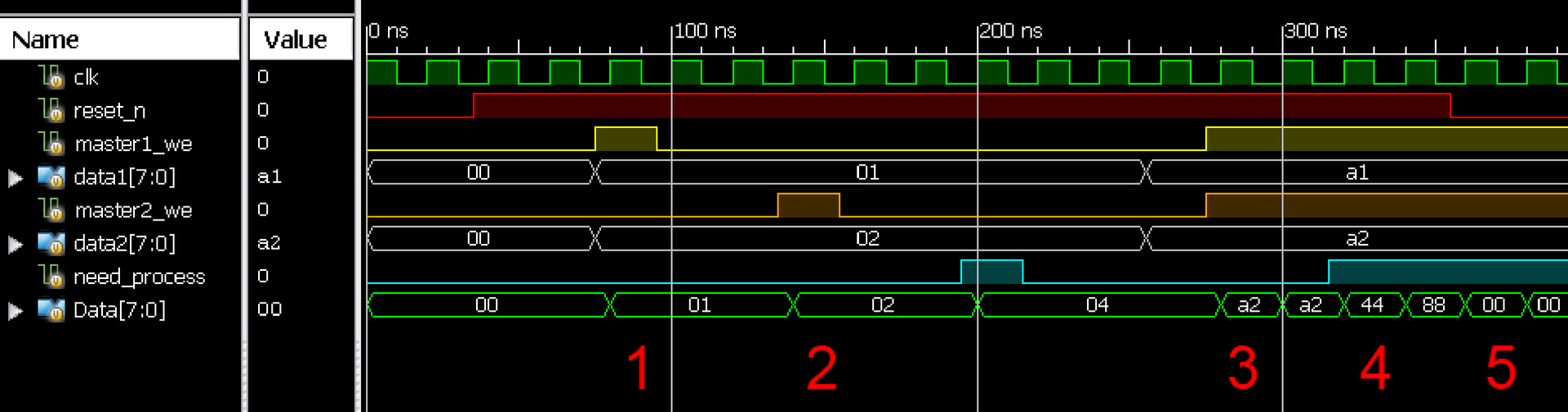
Pic2. Timing diagram of the simulation behavior of the description number 8
This system is controlled by several masters and arbitration between them is automatic. When the masters control the circuit in turn (phase 1 and 2, fig. 2), it receives data from each of them, but if several masters suddenly issue data simultaneously (phase 3, fig. 2), the circuit uses data from a higher priority master , whose interface is described below, from the second in our example.
In this case, the reset of the circuit overlaps all signals (phase 5, fig. 2), and the processing is higher in priority of any of the masters, but lower than the reset (phase 4, fig. 2).
Let us return to the initial example and show its final description:
input clk; // input data_we; // input [7:0] data; // reg [7:0] Data; // reg DataRdy; // reg [7:0] ProcessedData; // //--------------------------------------------------- // //--------------------------------------------------- always @(posedge clk) begin // ------------------------------- // 0 if(data_we == 1'b1)// begin Data <= data; // DataRdy <= 1'b1; // end // -------------------------- // 1 if(DataRdy == 1'b1) // begin // ProcessedData <= Data; DataRdy <= 1'b0; // , end end №9 It is not even necessary to check in the receiving block that the DataRdy is zero, the processing block will override the receive block by priority, and clear the DataRdy flag, even if new data is received during processing. And changing the blocks in places, we will not miss any new data.
input clk; // input data_we; // input [7:0] data; // reg [7:0] Data; // reg DataRdy; // reg [7:0] ProcessedData; // //--------------------------------------------------- // //--------------------------------------------------- always @(posedge clk) begin // -------------------------- // 0 if(DataRdy == 1'b1) // begin // ProcessedData <= Data; DataRdy <= 1'b0; // , end // ------------------------------- // 1 if(data_we == 1'b1)// begin Data <= data; // DataRdy <= 1'b1; // end end №10 After data processing, the DataRdy flag is reset, but if at the same time new data comes to us, the receiving unit will override the reset priority and set the DataRdy flag again, and the data (updating) will not be lost, the data will be processed in the next cycle.
What gives such an organization code?
The code is divided into clear blocks, you can give lengthy comments in front of them, which makes each block. We have the opportunity to prioritize the blocks, overlapping the assignments of one block to others, while not linking them into huge inconvenient if - else if - else if lists. You can delete or “comment out” the block, insert another one between any blocks, the rest of the code will continue to work without edits.
Since we have a single always, there are no conflicts of double signal sources, if at some point we decide to change the signals in different structural blocks. We simply change the signal where and when we need it. There is no need to organize any “handshakes” and “forward” additional signals, as in the case of separate always.
The code is manageable, read, change, exists according to understandable laws, you do not need to collect priority encoders and send them to the interface multiplexers, collecting all the signals on the bus and counting all the conditions of the signal change.
All you need is to simply describe the behavior of the circuit, what you want from it, set priorities by the location of the description blocks and give it all to the synthesizer. You can be sure that he will perfectly cope with the task and will produce a scheme with the desired behavior, the Xilinx synthesizer is accurate, but I think others will be in solidarity.
')
Source: https://habr.com/ru/post/321676/
All Articles