PROTEQ - multigigabit exchange protocol for Xilinx FPGA
Modern FPGAs contain multi-gigabit communication lines and there are a large number of protocols for exchange. However, upon closer examination, it is not always convenient to use standard protocols in FPGA. For example, for Xilinx FPGAs, PCI Express, RapidIO, Aurora; Each of them has flaws. PCI Express and RapidIO work with 8/10 encoding, which immediately limits throughput. Aurora can work with 64/66 encoding but does not provide data recovery after a crash. Taking into account the shortcomings of standard protocols and application features, I decided to implement my own exchange protocol.
The PROTEQ name was inherited from the previous project for which a similar idea of data recovery after a crash was expressed.
So the source data:
• hardware - module FMC106P, two FPGA Virtex 6 LX130T-2 and LX240T-1
• transfer rate - 5 Gbit / s
• number of lines - 8
• data source - ADC, there is no possibility to suspend the transfer
• bidirectional data exchange
• it is required to realize fast data recovery after failure
• encoding - 64/67
')
The basic idea is to implement a constant retransmission of data before the arrival of confirmation of the received packet. This is the main feature of the protocol and it is this that allows you to speed up data recovery.
Consider the implementation of one line:
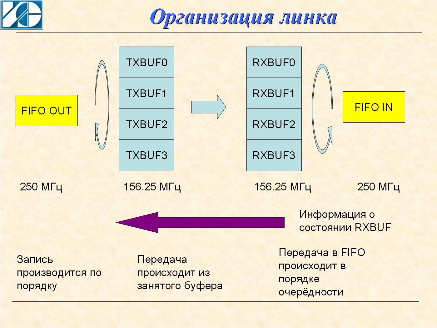
Four buffers are implemented on the transmitter. The data source detects a free buffer and writes data to it. Record goes in the strict order 0,1,2,3; The transmission node also polls the buffer fill flag in a circle and starts transmitting data from the filled buffers. When reception is received from the receiver, the buffer is marked free. With a large data stream, the confirmation has time to come before the transfer of all four buffers and the transfer is at maximum speed. With a small stream, the transmit node will have time to send a repeated packet, but it will be dropped on the receiving side.
This solution greatly speeds up data recovery. In the traditional scheme, the receiver must accept the packet, analyze it, and form a request for retransmission. This is a long time.
Four buffers are also implemented on the receiver. The packet header contains the buffer number and the packet is immediately sent to the destination buffer. In this decision there is a very big danger. If the buffer number is corrupted, it is possible that two packets will be corrupted - both the current packet and the packet already received. To avoid this, the package uses two checksums - one goes right after the heading, the second - at the end of the package.
For the 5 Gbps speed on the GTX node, a 32-bit bus with a frequency of 156.25 MHz is used. The exchange between the FIFO and internal buffers is at a frequency of 250 MHz. This provides a speed margin for recovery. For example, if an error occurred during transfer to buffer 1, and transfer to buffer 2 and 3 occurred without error, then writing to the output FIFO will be delayed until the packet comes back to buffer 1. But after that, packets from buffers 2 and 3 will be immediately written to the FIFO.
The protocol uses a fixed packet length of 256 words 32 bits each. There are two types of package:
Data packet format:
Service Package Format:
Overhead is quite low - only four 32-bit words. The total length of the data package is 260 words.
Service packets are transmitted in the absence of data.
To increase the speed of the transmission is implemented on several lines. There is a node that works with the number of lines from 1 to 8. For each line, the width of the data bus is 32 bits. When using 8 lines, the total data bus width is 256 bits.
The estimated exchange rate for eight lines at a frequency of 5 GHz:
It is this speed achieved as a result of experiments. Errors occur periodically, but they are corrected by the protocol. Fast recovery allows you to use a small FIFO size to connect the ADC.
It is interesting to compare the effectiveness of PROTEQ with PCI Express v2.0 implemented on the same FPGA. Both protocols use eight links at a speed of 5 Gbps. The maximum exchange rate is:
PROTEQ Efficiency:
PCI Express provides 3200 MB / s
3200/4768 = 0.67; those. 67% of maximum line speed.
Of course, the main reason for the low performance of PCI Express v2.0 is the use of 8/10 encoding;
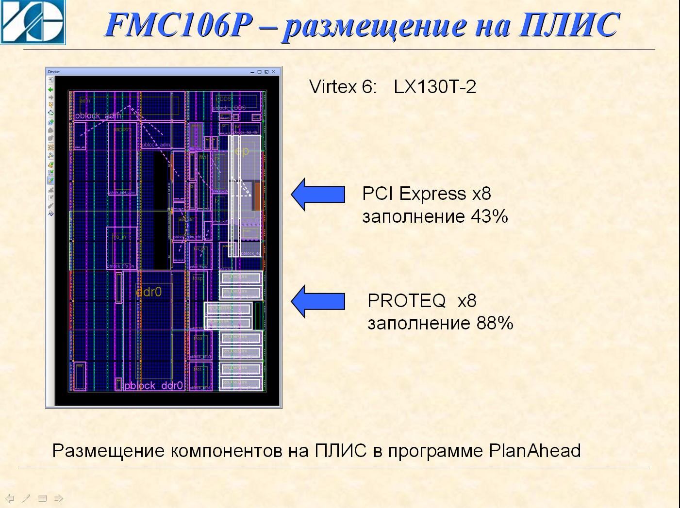
It is also interesting to compare the FPGA resources occupied for the implementation of protocols. The figure shows the areas that occupies PCI Express and PROTEQ with comparable functionality. It should be borne in mind that PCI Express uses another HARD unit.
The main component is prq_transceiver_gtx_m1
A group of tx_ * signals organizes the transmission channel. Pact Transfer Algorithm:
You can write from 1 to 256 words, but in any case, a packet of 256 words will be sent.
Similarly, the rx_ * signal group organizes the receive channel. Algorithm reception package:
Also, as with recording, it is allowed to read not the entire package. A four-bit header is transmitted along with the packet. When transmitting along with the packet, the input value tx_data_title will be transmitted. At reception, together with the readiness tx_ready = 1, a value will appear on rx_data_title. This allows you to have multiple sources and data receivers with one channel of transmission.
In addition, flags are transmitted in the channel. Data at the input of the transmitter tx_user_flag is transmitted to the output of the receiver rx_user_flag. This can be used to send FIFO status flags.
The prq_transceiver_gtx_m1 component can transfer data across multiple lines. The number of lines is configured via the LINES parameter; The width of tires tx_data, rx_data depends on the number of lines.
The tx_inject_error entry allows you to add an error during the transfer. This allows you to check the data recovery mechanism.
The next level is the component prq_connect_m1
He is already implementing a mechanism for transmitting data through the FIFO on eight lines. Structural scheme:

It consists of two FIFOs, prq_transceiver, receive and transmit automata.
The width of the input bus of each FIFO is configured through the FIFOx_WITH parameters, the word count and the trigger level of the almost full FIFO flag are also configured. Writing to each FIFO is done at its own clock frequency. Each FIFO is accompanied by its identifier fi0_id, fi1_id; This allows you to split the data stream at the reception. After the FIFO, a pseudo-random sequence generator is installed. In the diagram, it is designated as a PSD.
The generator implements three modes:
Testing in real projects is based on this generator. This generator does not take up much space in the FPGA, it is in all projects and allows you to check the exchange channel at any time.
The components prq_connect_m1 and prq_transceiver_gtx_m1 are basic. They were designed for FPGA Virtex 6; Subsequently, the components prq_transceiver_gtx_m4 and prq_transceiver_gtx_m6;
The project is fully modeled, a sequential test run via a tcl file is implemented
And here I want to express my gratitude to Igor Kazinov. He made a great contribution to the organization of modeling in this project.
The overall result of the simulation is as follows:
Each line in the file is the result of a single test. tc is a Test Case - a test case. For example, I will cite the tc_00_1 component - checking packet transmission and introducing a single error into the transmission process.
The component is very simple. It calls prq_transceiver_tb (and here it’s just complicated), adjusts the parameters and generates a tx_err signal which introduces an error to the transmission line.
The remaining components from tc_00_1 to tc_00_5 are about the same, they differ in the configured parameters, which allows you to check the data transmission under different conditions.
The prq_transceiver_tb component is much more complicated. Actually, it forms a test sequence, transmits the stream between two prq_transceiver_gtx_m1 and checks the received data stream. If necessary - introduces errors in the transfer process.
The component itself is here:
The result of the test:
Pay attention to the right column. This is the time between received packets. The usual time is ~ 1740 ns, but packet 2 is received with a delay of 8712 ns. This was just the error signal. And also note that the following packets are taken with a delay of 954 ns. This is due to the fact that only one packet was incorrectly received, while the others waited in the buffer memory for their turn.
I want to note that automated test execution helped me a lot when debugging a protocol. This allowed to keep all changes under control. And small changes in the source code could not lead to the collapse of the project.
The PROTEQ project is available as OpenSource. Link to the site - in my profile.
The PROTEQ name was inherited from the previous project for which a similar idea of data recovery after a crash was expressed.
So the source data:
• hardware - module FMC106P, two FPGA Virtex 6 LX130T-2 and LX240T-1
• transfer rate - 5 Gbit / s
• number of lines - 8
• data source - ADC, there is no possibility to suspend the transfer
• bidirectional data exchange
• it is required to realize fast data recovery after failure
• encoding - 64/67
')
The basic idea is to implement a constant retransmission of data before the arrival of confirmation of the received packet. This is the main feature of the protocol and it is this that allows you to speed up data recovery.
Consider the implementation of one line:
Four buffers are implemented on the transmitter. The data source detects a free buffer and writes data to it. Record goes in the strict order 0,1,2,3; The transmission node also polls the buffer fill flag in a circle and starts transmitting data from the filled buffers. When reception is received from the receiver, the buffer is marked free. With a large data stream, the confirmation has time to come before the transfer of all four buffers and the transfer is at maximum speed. With a small stream, the transmit node will have time to send a repeated packet, but it will be dropped on the receiving side.
This solution greatly speeds up data recovery. In the traditional scheme, the receiver must accept the packet, analyze it, and form a request for retransmission. This is a long time.
Four buffers are also implemented on the receiver. The packet header contains the buffer number and the packet is immediately sent to the destination buffer. In this decision there is a very big danger. If the buffer number is corrupted, it is possible that two packets will be corrupted - both the current packet and the packet already received. To avoid this, the package uses two checksums - one goes right after the heading, the second - at the end of the package.
For the 5 Gbps speed on the GTX node, a 32-bit bus with a frequency of 156.25 MHz is used. The exchange between the FIFO and internal buffers is at a frequency of 250 MHz. This provides a speed margin for recovery. For example, if an error occurred during transfer to buffer 1, and transfer to buffer 2 and 3 occurred without error, then writing to the output FIFO will be delayed until the packet comes back to buffer 1. But after that, packets from buffers 2 and 3 will be immediately written to the FIFO.
The protocol uses a fixed packet length of 256 words 32 bits each. There are two types of package:
- Data packet
- Service pack
Data packet format:
- CMD1
- CRC1
- DATA - 256 words
- CMD2
- CRC2
Service Package Format:
- CMD1
- CRC1
- CMD2
- CRC2
Overhead is quite low - only four 32-bit words. The total length of the data package is 260 words.
Service packets are transmitted in the absence of data.
To increase the speed of the transmission is implemented on several lines. There is a node that works with the number of lines from 1 to 8. For each line, the width of the data bus is 32 bits. When using 8 lines, the total data bus width is 256 bits.
The estimated exchange rate for eight lines at a frequency of 5 GHz:
5000000000 * 64/67 * 256/260 * 8/8/1024/1024 = 4484.7 MB / s
It is this speed achieved as a result of experiments. Errors occur periodically, but they are corrected by the protocol. Fast recovery allows you to use a small FIFO size to connect the ADC.
It is interesting to compare the effectiveness of PROTEQ with PCI Express v2.0 implemented on the same FPGA. Both protocols use eight links at a speed of 5 Gbps. The maximum exchange rate is:
5,000,000,000 / 8/1024/1024 * 8 = 4768 MB / s
PROTEQ Efficiency:
4484/4768 = 0.94; those. 94% of maximum line speed.
PCI Express provides 3200 MB / s
3200/4768 = 0.67; those. 67% of maximum line speed.
Of course, the main reason for the low performance of PCI Express v2.0 is the use of 8/10 encoding;
It is also interesting to compare the FPGA resources occupied for the implementation of protocols. The figure shows the areas that occupies PCI Express and PROTEQ with comparable functionality. It should be borne in mind that PCI Express uses another HARD unit.
The main component is prq_transceiver_gtx_m1
prq_transceiver_gtx_m1
component prq_transceiver_gtx_m1 is generic( is_simulation : in integer:=0; -- 1 - LINES : in integer; -- MGT RECLK_EN : in integer:=0; -- 1 - recclk -- 0 - txoutclk USE_REFCLK_IN : boolean:=FALSE; -- FALSE - MGTCLK -- TRUE - REFCLK_IN is_tx_dpram_use : in integer:=1; -- 1 - is_rx_dpram_use : in integer:=1 -- 1 - ); port( clk : in std_logic; -- - 266 clk_tx_out : out std_logic; -- - 156.25 clk_rx_out : out std_logic; -- - 156.25 --- SYNC --- reset : in std_logic; -- 0 - sync_done : out std_logic; -- 1 - tx_enable : in std_logic; -- 1 - rx_enable : in std_logic; -- 1 - rst_buf : in std_logic:='0'; -- 1 - transmitter_dis : in std_logic:='0'; -- 1 - ---- DATA ---- tx_ready : out std_logic; -- 1 - rx_ready : out std_logic; -- 1 - tx_data : in std_logic_vector( 31+(LINES-1)*32 downto 0 ); -- tx_data_we : in std_logic; -- 1 - tx_data_title : in std_logic_vector( 3 downto 0 ); -- tx_data_eof : in std_logic; -- 1 - tx_user_flag : in std_logic_vector( 7+(LINES-1)*8 downto 0 ); -- tx_inject_error : in std_logic_vector( LINES-1 downto 0 ):=(others=>'0'); -- 1 - rx_data : out std_logic_vector( 31+(LINES-1)*32 downto 0 ); -- rx_data_rd : in std_logic; -- 1 - rx_data_title : out std_logic_vector( 3 downto 0 ); -- rx_data_eof : in std_logic; -- 1 - rx_user_flag : out std_logic_vector( 7+(LINES-1)*8 downto 0 ); -- rx_user_flag_we : out std_logic_vector( (LINES-1) downto 0 ); -- 1 - rx_crc_error_adr: in std_logic_vector( 2 downto 0 ):="000"; -- rx_crc_error : out std_logic_vector( 7 downto 0 ); -- --- MGT --- rxp : in std_logic_vector( LINES-1 downto 0 ); rxn : in std_logic_vector( LINES-1 downto 0 ); txp : out std_logic_vector( LINES-1 downto 0 ); txn : out std_logic_vector( LINES-1 downto 0 ); refclk_in : in std_logic:='0'; mgtclk_p : in std_logic; mgtclk_n : in std_logic ); end component; A group of tx_ * signals organizes the transmission channel. Pact Transfer Algorithm:
- Wait tx_ready = 1
- Write a packet on the tx_data bus using the gate tx_data_we = 1
- Generate tx_data_eof = 1 per clock cycle - the packet will be sent
You can write from 1 to 256 words, but in any case, a packet of 256 words will be sent.
Similarly, the rx_ * signal group organizes the receive channel. Algorithm reception package:
- Wait for rx_ready = 1
- Read the packet on the rx_data bus using the rx_data_rd strobe
- Generate rx_data_eof = 1
Also, as with recording, it is allowed to read not the entire package. A four-bit header is transmitted along with the packet. When transmitting along with the packet, the input value tx_data_title will be transmitted. At reception, together with the readiness tx_ready = 1, a value will appear on rx_data_title. This allows you to have multiple sources and data receivers with one channel of transmission.
In addition, flags are transmitted in the channel. Data at the input of the transmitter tx_user_flag is transmitted to the output of the receiver rx_user_flag. This can be used to send FIFO status flags.
The prq_transceiver_gtx_m1 component can transfer data across multiple lines. The number of lines is configured via the LINES parameter; The width of tires tx_data, rx_data depends on the number of lines.
The tx_inject_error entry allows you to add an error during the transfer. This allows you to check the data recovery mechanism.
The next level is the component prq_connect_m1
prq_connect_m1
component prq_connect_m1 is generic( is_simulation : in integer:=0; -- 1 - RECLK_EN : in integer:=0; -- 1 - recclk -- 0 - txoutclk is_tx_dpram_use : in integer:=1; -- 1 - is_rx_dpram_use : in integer:=1; -- 1 - FIFO0_WITH : in integer:=1; -- FIFO0: 1 - , 32,64,128,256 FIFO0_PAF : in integer:=16; -- PAF FIFO0_DEPTH : in integer:=1024; -- FIFO0 FIFO1_WITH : in integer:=1; -- FIFO1: 1 - , 32,64,128,256 FIFO1_PAF : in integer:=16; -- PAF FIFO1_DEPTH : in integer:=1024 -- FIFO0 ); port( --- MGT --- rxp : in std_logic_vector( 7 downto 0 ); rxn : in std_logic_vector( 7 downto 0 ); txp : out std_logic_vector( 7 downto 0 ); txn : out std_logic_vector( 7 downto 0 ); mgtclk_p : in std_logic; mgtclk_n : in std_logic; ---- Tranceiver ---- clk : in std_logic; -- - 266 clk_tx_out : out std_logic; -- - 156.25 clk_rx_out : out std_logic; -- - 156.25 --- SYNC --- reset : in std_logic; -- 0 - sync_done : out std_logic; -- 1 - tx_enable : in std_logic; -- 1 - rx_enable : in std_logic; -- 1 - ---- FIFO0 ---- fi0_clk : in std_logic:='0'; -- FIFO fi0_data : in std_logic_vector( FIFO0_WITH-1 downto 0 ):=(others=>'0'); -- FIFO fi0_data_en : in std_logic:='0'; -- 1 - FIFO fi0_paf : out std_logic; -- 1 - FIFO fi0_id : in std_logic_vector( 3 downto 0 ):=(others=>'0'); -- FIFO fi0_rstp : in std_logic:='0'; -- 1 - FIFO fi0_enable : in std_logic:='0'; -- 1 - fi0_prs_en : in std_logic:='0'; -- 1 - fi0_ovr : out std_logic; -- 1 - FIFO fi0_rd_full_speed: in std_logic:='0'; -- 1 - ---- FIFO1 ---- fi1_clk : in std_logic:='0'; -- FIFO fi1_data : in std_logic_vector( FIFO1_WITH-1 downto 0 ):=(others=>'0'); -- FIFO fi1_data_en : in std_logic:='0'; -- 1 - FIFO fi1_paf : out std_logic; -- 1 - FIFO fi1_id : in std_logic_vector( 3 downto 0 ):=(others=>'0'); -- FIFO fi1_rstp : in std_logic:='0'; -- 1 - FIFO fi1_enable : in std_logic:='0'; -- 1 - fi1_prs_en : in std_logic:='0'; -- 1 - fi1_ovr : out std_logic; -- 1 - FIFO fi1_rd_full_speed: in std_logic:='0'; -- 1 - tx_inject_error : in std_logic_vector( 7 downto 0 ):=(others=>'0'); -- 1 - tx_user_flag : in std_logic_vector( 63 downto 0 ):=(others=>'0'); -- ---- ---- fifo_data : out std_logic_vector( 255 downto 0 ); -- FIFO fifo_we : out std_logic; -- 1 - fifo_id : out std_logic_vector( 3 downto 0 ); -- FIFO fifo_rdy : in std_logic_vector( 15 downto 0 ); -- rx_crc_error_adr: in std_logic_vector( 2 downto 0 ):="000"; -- rx_crc_error : out std_logic_vector( 7 downto 0 ); -- rx_user_flag : out std_logic_vector( 63 downto 0 ); -- rx_user_flag_we : out std_logic_vector( 7 downto 0 ) -- 1 - ); end component; He is already implementing a mechanism for transmitting data through the FIFO on eight lines. Structural scheme:
It consists of two FIFOs, prq_transceiver, receive and transmit automata.
The width of the input bus of each FIFO is configured through the FIFOx_WITH parameters, the word count and the trigger level of the almost full FIFO flag are also configured. Writing to each FIFO is done at its own clock frequency. Each FIFO is accompanied by its identifier fi0_id, fi1_id; This allows you to split the data stream at the reception. After the FIFO, a pseudo-random sequence generator is installed. In the diagram, it is designated as a PSD.
The generator implements three modes:
- Skip data stream unchanged
- Substitute test sequence while maintaining data rate
- Substitute test sequence and transfer data at full speed
Testing in real projects is based on this generator. This generator does not take up much space in the FPGA, it is in all projects and allows you to check the exchange channel at any time.
The components prq_connect_m1 and prq_transceiver_gtx_m1 are basic. They were designed for FPGA Virtex 6; Subsequently, the components prq_transceiver_gtx_m4 and prq_transceiver_gtx_m6;
- prq_transceiver_gtx_m4 - buffer 0 is allocated for transmitting the command
- prq_transceiver_gtx_m6 - for Kintex 7 FPGA
The project is fully modeled, a sequential test run via a tcl file is implemented
And here I want to express my gratitude to Igor Kazinov. He made a great contribution to the organization of modeling in this project.
The overall result of the simulation is as follows:
Global_tc_summary.log file
Global PROTEQ TC log: tc_00_0 PASSED tc_00_1 PASSED tc_00_2 PASSED tc_00_3 PASSED tc_02_0 PASSED tc_02_1 PASSED tc_02_2 PASSED tc_02_3 PASSED tc_02_4 PASSED tc_02_5 PASSED tc_03_0 PASSED tc_05_0 PASSED tc_05_1 PASSED Each line in the file is the result of a single test. tc is a Test Case - a test case. For example, I will cite the tc_00_1 component - checking packet transmission and introducing a single error into the transmission process.
tc_00_1
------------------------------------------------------------------------------- -- -- Title : tc_00_1 -- Author : Dmitry Smekhov -- Company : Instrumental Systems -- E-mail : dsmv@insys.ru -- -- Version : 1.0 -- ------------------------------------------------------------------------------- -- -- Description : prq_transceiver_tb -- -- 32- . -- -- ------------------------------------------------------------------------------- -- -- Rev0.1 - debug test #1 -- ------------------------------------------------------------------------------- library ieee; use ieee.std_logic_1164.all; use ieee.std_logic_arith.all; use ieee.std_logic_unsigned.all; library std; use std.textio.all; library work; use work.prq_transceiver_tb_pkg.all; -- to bind testbench and its procedures use work.utils_pkg.all; -- for "stop_simulation" use work.pck_fio.all; entity tc_00_1 is end tc_00_1; architecture bhv of tc_00_1 is signal tx_err : std_logic; signal rx_err : std_logic; begin ---------------------------------------------------------------------------------- -- Instantiate TB TB : prq_transceiver_tb generic map( max_pkg => 32, -- , max_time => 100 us, -- tx_pause => 1 ns, -- rx_pause => 1 ns -- ) port map( tx_err => tx_err, -- m1->m2 rx_err => rx_err -- m2->m1 ); ---------------------------------------------------------------------------------- -- -- Define ERR at TIME# -- tx_err <= '0', '1' after 27 us, '0' after 27.001 us; rx_err <= '0'; ---------------------------------------------------------------------------------- end bhv; The component is very simple. It calls prq_transceiver_tb (and here it’s just complicated), adjusts the parameters and generates a tx_err signal which introduces an error to the transmission line.
The remaining components from tc_00_1 to tc_00_5 are about the same, they differ in the configured parameters, which allows you to check the data transmission under different conditions.
The prq_transceiver_tb component is much more complicated. Actually, it forms a test sequence, transmits the stream between two prq_transceiver_gtx_m1 and checks the received data stream. If necessary - introduces errors in the transfer process.
The component itself is here:
prq_transceiver_tb
library ieee; use ieee.std_logic_1164.all; use ieee.std_logic_arith.all; use ieee.std_logic_unsigned.all; use work.prq_transceiver_gtx_m1_pkg.all; library std; use std.textio.all; use work.pck_fio.all; use work.utils_pkg.all; entity prq_transceiver_tb is generic( max_pkg : integer:=0; -- , max_time : time:=100 us; -- tx_pause : time:=100 ns; -- rx_pause : time:=100 ns -- ); port( tx_err : in std_logic:='0'; -- m1->m2 rx_err : in std_logic:='0' -- m2->m1 ); end prq_transceiver_tb; architecture TB_ARCHITECTURE of prq_transceiver_tb is signal clk : std_logic:='0'; signal reset : STD_LOGIC; signal tx_data : STD_LOGIC_VECTOR(31 downto 0); signal tx_data_we : STD_LOGIC; signal tx_data_title : STD_LOGIC_VECTOR(3 downto 0); signal rx_data_rd : STD_LOGIC; signal rxp : STD_LOGIC_VECTOR(0 downto 0); signal rxn : STD_LOGIC_VECTOR(0 downto 0); signal mgtclk_p : STD_LOGIC; signal mgtclk_n : STD_LOGIC; signal mgtclk : std_logic:='0'; -- Observed signals - signals mapped to the output ports of tested entity signal clk_tx_out : STD_LOGIC; signal clk_rx_out : STD_LOGIC; signal sync_done : STD_LOGIC; signal tx_enable : STD_LOGIC; signal rx_enable : STD_LOGIC; signal tx_ready : STD_LOGIC; signal rx_ready : STD_LOGIC; signal rx_data : STD_LOGIC_VECTOR(31 downto 0); signal rx_data_title : STD_LOGIC_VECTOR(3 downto 0); signal txp : STD_LOGIC_VECTOR(0 downto 0); signal txn : STD_LOGIC_VECTOR(0 downto 0); signal m2_txp : STD_LOGIC_VECTOR(0 downto 0); signal m2_txn : STD_LOGIC_VECTOR(0 downto 0); signal m2_rxp : STD_LOGIC_VECTOR(0 downto 0); signal m2_rxn : STD_LOGIC_VECTOR(0 downto 0); signal tx_err_i : std_logic_vector( 0 downto 0 ); signal rx_err_i : std_logic_vector( 0 downto 0 ); signal tx_data_eof : std_logic; signal rx_data_eof : std_logic; signal m2_clk : std_logic:='0'; signal m2_tx_data : STD_LOGIC_VECTOR(31 downto 0); signal m2_tx_data_we : STD_LOGIC; signal m2_tx_data_title : STD_LOGIC_VECTOR(3 downto 0); signal m2_rx_data_rd : STD_LOGIC; signal m2_tx_data_eof : std_logic; signal m2_rx_data_eof : std_logic; -- Observed signals - signals mapped to the output ports of tested entity signal m2_clk_tx_out : STD_LOGIC; signal m2_clk_rx_out : STD_LOGIC; signal m2_sync_done : STD_LOGIC; signal m2_tx_enable : STD_LOGIC; signal m2_rx_enable : STD_LOGIC; signal m2_tx_ready : STD_LOGIC; signal m2_rx_ready : STD_LOGIC; signal m2_rx_data : STD_LOGIC_VECTOR(31 downto 0); signal m2_rx_data_title : STD_LOGIC_VECTOR(3 downto 0); signal tx_user_flag : std_logic_vector( 7 downto 0 ):=x"A0"; signal rx_user_flag : std_logic_vector( 7 downto 0 ); signal rx_user_flag_we : std_logic_vector( 0 downto 0 ); signal m2_tx_user_flag : std_logic_vector( 7 downto 0 ):=x"C0"; signal m2_rx_user_flag : std_logic_vector( 7 downto 0 ); signal m2_rx_user_flag_we : std_logic_vector( 0 downto 0 ); signal m2_reset : std_logic; begin clk <= not clk after 1.9 ns; mgtclk <= not mgtclk after 3.2 ns; m2_clk <= not m2_clk after 1.8 ns; mgtclk_p <= mgtclk; mgtclk_n <= not mgtclk; -- Unit Under Test port map UUT : prq_transceiver_gtx_m1 generic map ( is_simulation => 1, -- 1 - LINES => 1, is_tx_dpram_use => 1, -- 1 - is_rx_dpram_use => 0 -- 1 - ) port map ( clk => clk, clk_tx_out => clk_tx_out, clk_rx_out => clk_rx_out, --- SYNC --- --- SYNC --- reset => reset, sync_done => sync_done, tx_enable => tx_enable, rx_enable => rx_enable, ---- DATA ---- ---- DATA ---- tx_ready => tx_ready, rx_ready => rx_ready, tx_data => tx_data, tx_data_we => tx_data_we, tx_data_title => tx_data_title, tx_data_eof => tx_data_eof, tx_user_flag => tx_user_flag, rx_data => rx_data, rx_data_rd => rx_data_rd, rx_data_title => rx_data_title, rx_data_eof => rx_data_eof, rx_user_flag => rx_user_flag, rx_user_flag_we => rx_user_flag_we, --- MGT --- --- MGT --- rxp => rxp, rxn => rxn, txp => txp, txn => txn, mgtclk_p => mgtclk_p, mgtclk_n => mgtclk_n ); UUT2 : prq_transceiver_gtx_m1 generic map ( is_simulation => 1, -- 1 - LINES => 1, is_tx_dpram_use => 0, -- 1 - is_rx_dpram_use => 1 -- 1 - ) port map ( clk => m2_clk, clk_tx_out => m2_clk_tx_out, clk_rx_out => m2_clk_rx_out, --- SYNC --- --- SYNC --- reset => m2_reset, sync_done => m2_sync_done, tx_enable => m2_tx_enable, rx_enable => m2_rx_enable, ---- DATA ---- ---- DATA ---- tx_ready => m2_tx_ready, rx_ready => m2_rx_ready, tx_data => m2_tx_data, tx_data_we => m2_tx_data_we, tx_data_title => m2_tx_data_title, tx_data_eof => m2_tx_data_eof, tx_user_flag => m2_tx_user_flag, rx_data => m2_rx_data, rx_data_rd => m2_rx_data_rd, rx_data_title => m2_rx_data_title, rx_data_eof => m2_rx_data_eof, rx_user_flag => m2_rx_user_flag, rx_user_flag_we => m2_rx_user_flag_we, --- MGT --- --- MGT --- rxp => m2_rxp, rxn => m2_rxn, txp => m2_txp, txn => m2_txn, mgtclk_p => mgtclk_p, mgtclk_n => mgtclk_n ); rx_err_i <= (others=>rx_err); tx_err_i <= (others=>tx_err); rxp <= m2_txp or rx_err_i; rxn <= m2_txn or rx_err_i; m2_rxp <= txp or tx_err_i; m2_rxn <= txn or tx_err_i; reset <= '0', '1' after 1 us; m2_reset <= '0', '1' after 2 us; tx_enable <= '0', '1' after 22 us; rx_enable <= '0', '1' after 22 us; m2_tx_enable <= '0', '1' after 24 us; m2_rx_enable <= '0', '1' after 24 us; m2_tx_data_we <= '0'; m2_tx_data <= (others=>'0'); m2_tx_data_title <= "0000"; m2_tx_data_eof <= '0'; pr_tx_data: process begin tx_data_we <= '0'; tx_data_eof <= '0'; tx_data <= x"AB000000"; tx_data_title <= "0010"; loop wait until rising_edge( clk ) and tx_ready='1'; tx_data_we <= '1' after 1 ns; for ii in 0 to 255 loop wait until rising_edge( clk ); tx_data <= tx_data + 1 after 1 ns; end loop; tx_data_we <= '0' after 1 ns; wait until rising_edge( clk ); tx_data_eof <= '1' after 1 ns; wait until rising_edge( clk ); tx_data_eof <= '0' after 1 ns; wait until rising_edge( clk ); wait for tx_pause; end loop; end process; pr_rx_data: process variable expect_data : std_logic_vector( 31 downto 0 ):= x"AB000000"; variable error_cnt : integer:=0; variable pkg_cnt : integer:=0; variable pkg_ok : integer:=0; variable pkg_error : integer:=0; variable index : integer; variable flag_error : integer; variable tm_start : time; variable tm_stop : time; variable byte_send : real; variable tm : real; variable velocity : real; variable tm_pkg : time:=0 ns; variable tm_pkg_delta : time:=0 ns; variable L : line; begin m2_rx_data_rd <= '0'; m2_rx_data_eof <= '0'; --fprint( output, L, " \n" ); loop loop wait until rising_edge( m2_clk ); if( m2_rx_ready='1' or now>max_time ) then exit; end if; end loop; if( now>max_time ) then exit; end if; if( pkg_cnt=0 ) then tm_start:=now; tm_pkg:=now; end if; tm_pkg_delta := now - tm_pkg; fprint( output, L, "PKG=%3d %10r ns %10r ns\n", fo(pkg_cnt), fo(now), fo(tm_pkg_delta) ); tm_pkg:=now; index:=0; flag_error:=0; m2_rx_data_rd <= '1' after 1 ns; wait until rising_edge( m2_clk ); loop wait until rising_edge( m2_clk ); if( expect_data /= m2_rx_data ) then if( error_cnt<32 ) then fprint( output, L, "ERROR: pkg=%d index=%d expect=%r read=%r \n", fo(pkg_cnt), fo(index), fo(expect_data), fo(m2_rx_data) ); end if; error_cnt:=error_cnt+1; flag_error:=1; end if; index:=index+1; expect_data:=expect_data+1; if( index=255 ) then m2_rx_data_rd <= '0' after 1 ns; end if; if( index=256 ) then exit; end if; end loop; if( flag_error=0 ) then pkg_ok:=pkg_ok+1; else pkg_error:=pkg_error+1; end if; wait until rising_edge( m2_clk ); m2_rx_data_eof <= '1' after 1 ns; wait until rising_edge( m2_clk ); m2_rx_data_eof <= '0' after 1 ns; wait until rising_edge( m2_clk ); --wait until rising_edge( m2_clk ); wait for rx_pause; pkg_cnt:=pkg_cnt+1; if( pkg_cnt=max_pkg ) then exit; end if; end loop; tm_stop:=now; fprint( output, L, " : %r ns\n", fo(now) ); fprint( output, L, " : %d\n", fo( pkg_cnt ) ); fprint( output, L, " : %d\n", fo( pkg_ok ) ); fprint( output, L, " : %d\n", fo( pkg_error ) ); fprint( output, L, " : %d\n", fo( error_cnt ) ); byte_send:=real(pkg_cnt)*256.0*4.0; tm := real(tm_stop/ 1 ns )-real(tm_start/ 1 ns); velocity := byte_send*1000000000.0/(tm*1024.0*1024.0); fprint( output, L, " : %r /\n", fo( integer(velocity) ) ); flag_error:=0; if( max_pkg>0 and pkg_cnt/=max_pkg ) then flag_error:=1; end if; if( flag_error=0 and pkg_cnt>0 and error_cnt=0 ) then --fprint( output, L, "\n\n \n\n" ); fprint( output, L, "\n\nTEST finished successfully\n\n" ); else --fprint( output, L, "\n\n \n\n" ); fprint( output, L, "\n\nTEST finished with ERR\n\n" ); end if; utils_stop_simulation; wait; end process; pr_tx_user_flag: process begin tx_user_flag <= tx_user_flag + 1; wait for 1 us; end process; pr_m2_tx_user_flag: process begin m2_tx_user_flag <= m2_tx_user_flag + 1; wait for 1.5 us; end process; end TB_ARCHITECTURE; The result of the test:
tc_00_1.log
# KERNEL: PKG= 0 25068 ns 0 ns # KERNEL: PKG= 1 26814 ns 1746 ns # KERNEL: PKG= 2 35526 ns 8712 ns # KERNEL: PKG= 3 36480 ns 954 ns # KERNEL: PKG= 4 37434 ns 954 ns # KERNEL: PKG= 5 38388 ns 954 ns # KERNEL: PKG= 6 39342 ns 954 ns # KERNEL: PKG= 7 40858 ns 1515 ns # KERNEL: PKG= 8 42597 ns 1738 ns # KERNEL: PKG= 9 44339 ns 1742 ns # KERNEL: PKG= 10 46081 ns 1742 ns # KERNEL: PKG= 11 47827 ns 1746 ns # KERNEL: PKG= 12 49566 ns 1738 ns # KERNEL: PKG= 13 51309 ns 1742 ns # KERNEL: PKG= 14 53051 ns 1742 ns # KERNEL: PKG= 15 54790 ns 1738 ns # KERNEL: PKG= 16 56536 ns 1746 ns # KERNEL: PKG= 17 58278 ns 1742 ns # KERNEL: PKG= 18 60021 ns 1742 ns # KERNEL: PKG= 19 61759 ns 1738 ns # KERNEL: PKG= 20 63502 ns 1742 ns # KERNEL: PKG= 21 65248 ns 1746 ns # KERNEL: PKG= 22 66990 ns 1742 ns # KERNEL: PKG= 23 68729 ns 1738 ns # KERNEL: PKG= 24 70471 ns 1742 ns # KERNEL: PKG= 25 72210 ns 1738 ns # KERNEL: PKG= 26 73953 ns 1742 ns # KERNEL: PKG= 27 75699 ns 1746 ns # KERNEL: PKG= 28 77441 ns 1742 ns # KERNEL: PKG= 29 79180 ns 1738 ns # KERNEL: PKG= 30 80922 ns 1742 ns # KERNEL: PKG= 31 82661 ns 1738 ns # KERNEL: : 83598 ns # KERNEL: : 32 # KERNEL: : 32 # KERNEL: : 0 # KERNEL: : 0 # KERNEL: : 534 / # KERNEL: # KERNEL: # KERNEL: TEST finished successfully Pay attention to the right column. This is the time between received packets. The usual time is ~ 1740 ns, but packet 2 is received with a delay of 8712 ns. This was just the error signal. And also note that the following packets are taken with a delay of 954 ns. This is due to the fact that only one packet was incorrectly received, while the others waited in the buffer memory for their turn.
I want to note that automated test execution helped me a lot when debugging a protocol. This allowed to keep all changes under control. And small changes in the source code could not lead to the collapse of the project.
The PROTEQ project is available as OpenSource. Link to the site - in my profile.
Source: https://habr.com/ru/post/321634/
All Articles