PIC Controller Programming Tools
Introduction
PIC controllers remain popular in cases where you need to create an inexpensive, low-power, compact system that does not have high management requirements. These controllers allow you to replace hardware logic with flexible software tools that interact with external devices through good ports.
Miniature PIC controllers are good for building serial data interface converters, for implementing “receive-process-transfer data” functions and simple controls of automatic control systems.
Microchip distributes MPLAB, a free integrated editing and debugging environment for programs that writes binary files to PIC microcontrollers through programmers.
')
The interaction of MPLAB and Matlab / Simulink allows you to develop programs for PIC controllers in the Simulink environment - graphical modeling and analysis of dynamic systems. This paper discusses the PIC controller programming tools: MPLAB, Matlab / Simulink, and the PIC-KIT3 programmer in the following sections.
• Characteristics of the PIC12F629 miniature PIC controller
• Integrated Development Environment MPLAB IDE
• Connect Matlab / Simulink to MPLAB
• Connecting the PIC-KIT3 programmer
Characteristics of a miniature PIC controller
The PIC12xxx family contains controllers in a miniature 8-pin package with built-in clock generator. The controllers have a RISC-architecture and provide the execution of most processor commands in one machine cycle.
For example, below are the characteristics of an inexpensive compact 8-bit PIC12F629 controller with multifunctional ports, low power consumption and a wide power range [1].
• Architecture: RISC
• VDD power supply: 2.0V to 5.5V (<6.5V)
• Consumption:
- <1.0 mA @ 5.5V, 4MHz
- 20 µA (type) @ 32 kHz, 2.0 V
- <1.0 µA (type) in SLEEP @ 2.0V mode
• Power Dissipation: 0.8W
• Multifunctional I / O channels: 6/5
• Maximum output current of GPIO ports: 125mA
• Current through programmable internal pull-up port resistors: ≥50 (250) ≤400 µA @ 5.0V
• Controller bit depth: 8
• Clock frequency from external oscillator: 20 MHz
Machine cycle time: 200 ns
• Clock frequency from internal RC oscillator: 4 MHz ± 1%
Machine cycle time: 1µs
• FLASH program memory: 1K
Number of erase / write cycles: ≥1000
• RAM Data Memory: 64
• EEPROM data memory: 128
Number of erase / write cycles: ≥10K (-40 ° C ≤TA≤ + 125 ° C)
• Specialized hardware registers: 16
• List of commands: 35 instructions, all commands are executed in one machine cycle,
except for transition commands, performed in 2 cycles
• Hardware stack: 8 levels
• Timer / counter TMR0: 8-bit with a prescaler
• Timer / counter TMR1: 16-bit with a prescaler
Additional features:
• Power On Reset (POR)
• Reset timer (PWRT timer for generator start (OST
• Blowdown voltage reset (BOD)
• WDT Watchdog
• Multiplexing -MCLR output
• Interrupt system for changing the signal level at the inputs
• Pull resistors individually programmable for each input
• Programmable input protection
• Low Power Mode SLEEP
• Selection of the operating mode of the clock generator
• In-circuit ICSP programming using two pins
• Four user ID cells
The maximum operating temperature for the E version (extended range) is from -40 ° C to +125 ° C;
Storage temperature is from -65 ° C to +150 ° C.
The CMOS controller technology provides a completely static mode of operation, in which stopping the clock generator does not lead to the loss of logical states of the internal nodes.
The PIC12F629 microcontroller has a 6-bit GPIO I / O port. One GP3 pin of the GPIO port works only at the input, the remaining pins can be configured to work both at the input and at the output. Each GPIO pin has an individual interrupt enable bit for changing the signal level at the inputs and the enable bit of the internal pull-up resistor.
Integrated Development Environment MPLAB IDE
MPLAB IDE - a free integrated development environment for software for PIC microcontrollers includes tools for creating, editing, debugging, translating and linking programs, writing machine code to microcontrollers through programmers.
Download MPLAB IDE
Free versions of MPLAB (including MPLAB 8.92) are stored on the Microchip website in the DOWNLOAD ARCHIVE section.
Project creation
An example of creating a project for a PIC controller program in MPLAB includes the following steps [2].
1. Call the project manager.
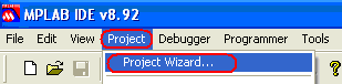
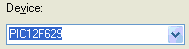
2. Select the type of PIC microcontroller.
3. Select a compiler, for example, Microchip MPASM for the assembler.

4. Select the path to the project directory (Browse button ...) and enter the project name.
5. It is possible not to connect files to a project in the Project Wizard → Step Four window. This can be done later, inside the active project. The Next button opens the next window.
6. Completion of the project creation (Finish button).
As a result of the creation of the project FirstPrMPLAB, the MPLAB interface takes the form shown in Fig. one.
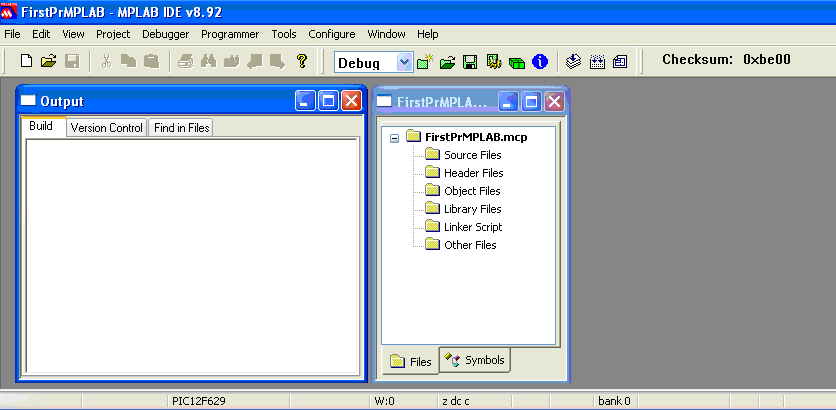
Fig. 1 . MPLAB v8.92 environment interface and project template.
Creating a program file
The program can be created using any text editor. MPLAB has a built-in editor that provides a number of advantages, for example, operational lexical analysis of the source text, as a result of which reserved words, constants, comments, user-defined names are highlighted in text.
Creating a program in MPLAB can be done in the following sequence.
1. Open the program editor: menu → File → New. Initially, the program is named Untitled.
2. Type or copy a program, for example, in assembly language.
3. Save the program under a different name (menu → File → Save As), for example, FirstPrMPLAB.asm.
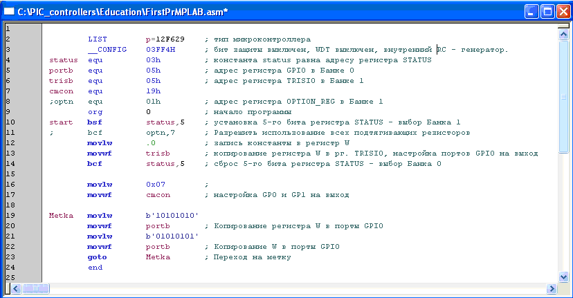
Fig. 2 An example of the simplest program (in assembler) output signals through the ports of the controller GP0, GP1, GP2, GP4, GP5 at the maximum frequency.
The entry '1' in the register register TRISIO transfers the corresponding output buffer to the 3rd state, in this case the GP port can only work as an input. Setting zero in TRISIO adjusts the operation of the GP port to the output.
Note. According to the PIC12F629 specification, the GP3 port of the microcontroller works only at the input (the corresponding bit of the TRISIO register is not reset — it is always in '1').
The TRISIO and GPIO registers are located in different banks of the memory area. Bank switching is performed with the 5th bit of the STATUS register.
Any assembler program starts with the org directive and ends with the end directive. Goto Metka transition provides cyclical program execution.
The program (Fig. 2) uses the following notation.
LIST directive - controller type assignment
__CONFIG directive - setting controller configuration bits
Equ directive - assignment of a numerical value
Directive org 0 - the beginning of the program from the address 0
The bsf command sets the specified register bit to 1
Command bcf - clears the bit of the specified register in 0
Movlw command - writes a constant to the register W
The movwf command - copies the contents of the register W to the specified register
The goto command - provides a transition without a condition to the line with a label
Directive end - end of the program
Setting the required microcontroller configuration
The configuration of the PIC12F629 microcontroller depends on the configuration word settings (2007h), which can be set in the program via the __CONFIG directive.
Directly or through the MPLAB window: menu → Configure → Configuration Bits:
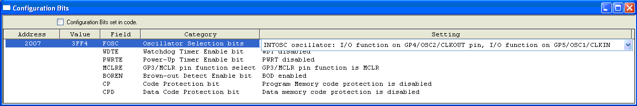
Where:
Bit 2-0 - FOSC2: FOSC0. Choosing a clock generator
111 - External RC generator. Connects to GP5 pin. GP4 works like CLKOUT
110 - External RC generator. Connects to GP5 pin. GP4 works as I / O
101 - Internal 4 MHz RC generator. GP5 works as I / O. GP4 - like CLKOUT
100 - Internal 4 MHz RC generator. GP5 and GP4 work as I / O
011 - EC generator. GP4 works as I / O. GP5 - like CLKIN
010 - HC generator. Resonator connects to GP4 and GP5
001 - XT generator. Resonator connects to GP4 and GP5
000 - LP generator. Resonator connects to GP4 and GP5
Bit 3 - WDTE: Watchdog Timer Setting
1 - WDTE enabled
0 - WDTE off
The watchdog timer prevents the microcontroller from hanging up - it restarts the program at a certain time interval if the timer has not been reset. The timer period is set in the OPTION_REG register. Resetting the watchdog timer is invoked with the CLRWDT command.
Bit 4 - PWRTE: Enable Power On Timer:
1 - PWRT is off
0 - PWRT enabled
The timer delays the microcontroller in a reset state when powering up the VDD.
Bit 5 - MCLR: Selecting the operating mode of the GP3 / -MCLR output
1 - works as -MCLR
0 - works as a GP3 I / O port
Bit 6 - BODEN: Enable Power- On Drop Voltage (typically <2.0V)
1 - BOR reset allowed
0 - the BOR reset is disabled; the timer is automatically activated.
When resetting the BOR, the PWRT timer is automatically activated.
Bit 7 - .CP: Bit protect program memory from reading by the programmer
1 protection off
0 protection enabled
When protection is turned off, all program memory is erased.
Bit 8 - .CPD: Bit EPROM Data Memory Protection
1 protection off
0 protection enabled
After disabling protection, all information will be erased.
Bit 11-9 - Not Used: Reads as '1'.
Bit 13-12 - BG1: BG0. Power Drop Calibration Bits
00 - lower calibration limit
11 - upper calibration limit
Adding a program to a project
An example of adding a program to a project is shown in (Fig. 3).
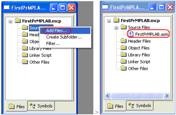
Fig. 3 Adding the program FirstPrMPLAB.asm to the project FirstPrMPLAB.mcp
You can save project materials using the command: menu → File → Save Workspace.
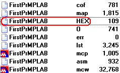
Compilation
To create a binary file with the extension hex for the microcontroller firmware, it is necessary to compile the project. The compilation is started by the menu command → Project → Build All. The compilation results can be seen in the Output window (Figure 1). If there are no errors in the program, the compiler gives a message about successful compilation: BUILD SUCCEEDED, the boot HEX file can be found in the working directory:
Debugging program
MPLAB IDE can be used to debug a program using the MPLAB REAL ICE hardware emulator or the software simulator MPLAB SIM. The launch of the latter is performed as shown in Fig. four.

Fig. 4 Connection to MPLAB SIM simulator for debugging the program.
After launching the debugger, the MPLAB SIM tab appears in the Output window (Fig. 1), where MPLAB displays the current debugger information. Debugger commands (Fig. 5) become active after launch.
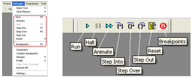
Fig. 5 Debugger commands.
Debugger Commands:
• Run - Continuous execution of the program to a breakpoint (if it is set).
• Halt - Stop the program at the current execution step.
• Animate - Animation of continuous program execution.
• Step Into - Perform step by step (Call calls are made in one step).
• Step Over - Perform steps including Call Call commands.
• Reset - Initial installation of the program. Move the pointer to the first command.
• Breakpoints - Displays a list of breakpoints. Processing list
When executing the program step by step, the current step is highlighted by an arrow (Fig. 6). Continuous program execution is stopped with a Halt command or when a program reaches a breakpoint. The breakpoint is set / removed in the program line by double clicking.
An example of an assembler program that changes the state of the controller ports at maximum speed is shown in Fig. 6 (right). The program transfers the data of b'10101010 'and b'01010101' to the GPIO port register. Since in the GPIO register, data transfer to the controller ports is not performed by all bits, but by only 0,1,2,4 and 5, the state of the GPIO register (Fig. 6, left) differs by the values b'00100010 'and b'00010101'.
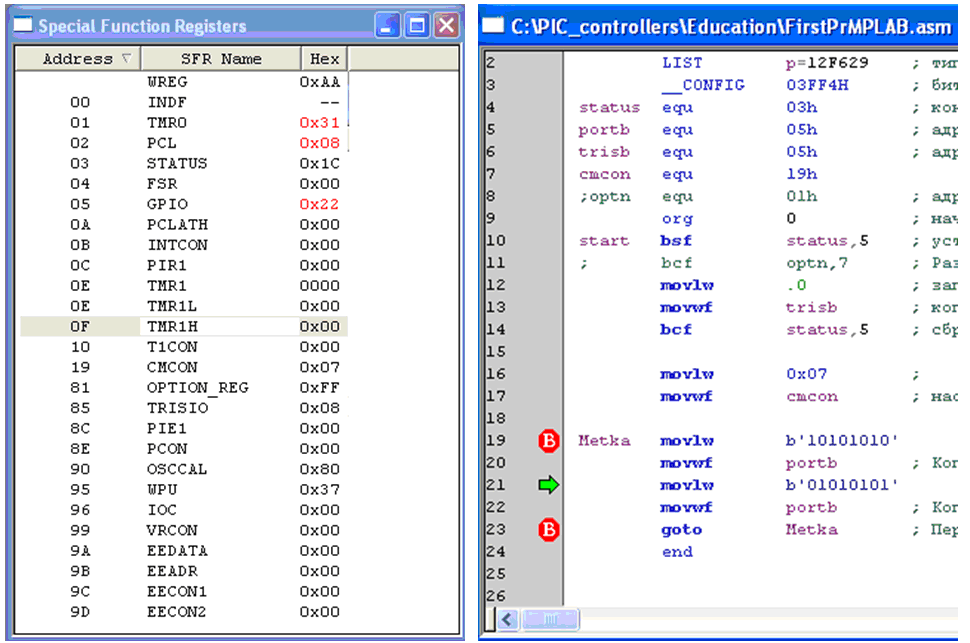
Fig. 6 The state of the controller's special-purpose registers at the time of program execution (left) and the program executed in steps (right).
In the process of debugging, you can monitor the status of registers, variables, memory in the corresponding windows opened in the View section of the main menu. In the process of debugging, you can make changes to the program code, the contents of registers, memory, change the values of variables. After changing the code, you must recompile the program. Changing the contents of registers, memory and values of variables (windows in the View section: Special Function Register, File Register, EEPROM, Watch) does not require recompilation.
The input signals of the microcontroller model ports can be defined in the Debugger → Stimulus section. Settable signal states of ports are tied to debug time (ticks).
Sometimes the results of running the program in debug mode do not correspond to the execution of the same program in a real controller, for example, the program debugger (Fig. 6) without instructions movlw 0x07 and movwf cmcon shows that the outputs of GP0 and GP1 of the GPIO register do not change - they are in zero state, the contents of the GPIO register are alternately 0x14 and 0x20. However, the controller that executes the program without the specified instructions shows on the oscilloscope the cyclic operation of all five outputs: 0x15 and 0x22, including GP0 and GP1 (see Fig. 7).
Oscillograms of the controller performing the program cycles 6 (Metka ... goto Metka) are shown in Fig. 7

Fig. 7 Oscillograms of GP0 output (left) and GP1 (right) of a PIC12F629 microcontroller operating from an internal 4 MHz RC oscillator. The program (Fig. 6) generates the maximum frequency signals at all outputs of the controller. During the period of 5.3 µs signals, 5 commands are executed (6 machine cycles), the amplitude of the GP0 signal on the oscillogram is 4.6 V, the power supply of the controller is 4.75 V, measured by the programmer.
Microcontroller firmware
To write the program to the microcontroller (controller firmware), you need to connect the microcontroller to the integrated environment MPLAB IDE through the programmer. Connection organization is shown below in the “Connecting the PIC-KIT3 Programmer” section.
Note. The PIC12F629 controller contains a factory calibration constant for setting the frequency of the internal clock generator. If necessary, it can be read and restored using MPLAB using the programmer.
Commands for working with the programmer and changing its settings are in the MPLAB Programmer menu. The type of programmer in MPLAB is selected in section: menu → Programmer → Select Programmer.
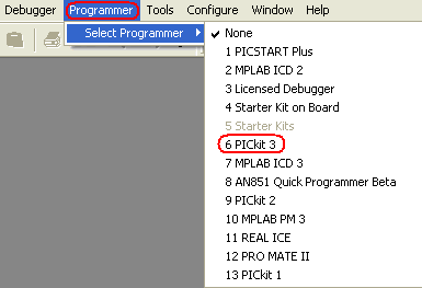
Fig. 8 Select a programmer to connect to the MPLAB environment.
The firmware of the microcontroller through the programmer is started by the command: menu → Programmer → Program. The message about the successful firmware is shown in Fig. 9.
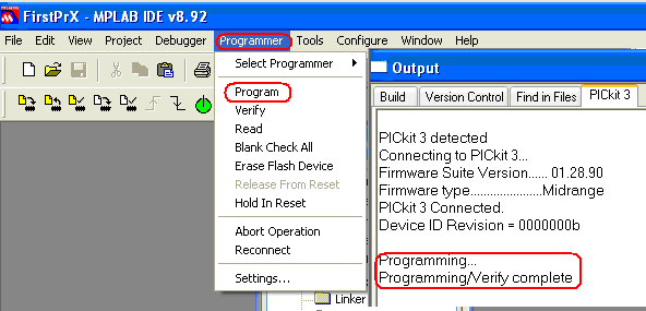
Fig. 9 The launch of the microcontroller firmware and the kind of message about successful firmware.
Note: During the microcontroller firmware, the yellow LED flashes on the PIC-KIT3 programmer.
Connect MATLAB / SIMULINK to MPLAB
In the simulation system of dynamic systems Simulink (application for Matlab) in the language of graphical programming [7], you can develop programs for a family of PIC controllers with ADC / DAC, counters, timers, PWM, DMA, interfaces UART, SPI, CAN, I2C, etc.
An example of the Simulink PIC controller program is shown in Fig. ten.

Fig. 10 An example of a program in graphical programming language for a PIC controller made in the Simulink dynamic systems simulation environment.
The interaction of development tools and compilation of programs for PIC controllers in Simulink is shown in Fig. 11 [6].

Fig. 11 The structure of the means of building an adequate PIC controller model in graphical programming language.
To build a development environment, the following Matlab components are needed:
• Simulink
• Real-Time Workshop Embedded Coder
• Real-Time Workshop
And the Microchip C compiler:
• C30 for PIC24, dsPIC30 and PIC33 controllers
• or C32 for PIC32 controllers
Installing Matlab Components
The site has Simulink libraries (dsPIC Toolbox) for PIC controllers and Matlab versions from R2006a to R2012a:
To download the library you need to register. The programs support 100 microcontrollers from the PIC 16MC, 24F, 30F, 32MC, 33F, 56GP, 64MC, 128MC, 128GP series.
Free versions work with Simulink models of PIC controllers with up to 7 I / O ports.
To install dsPIC Toolbox - the library of PIC controllers for Matlab / Simulink is necessary [4]:
• Download dsPIC Toolbox for the required version of Matlab.
• Unzip the file in the folder in which the Simulink blocks will be installed.
• Launch Matlab.
• Set the current Matlab directory to the folder with the unpacked file.
• Open and run the install_dsPIC_R2012a.m file, for example, a menu button or a keyboard key.
The dsPIC libraries and examples of Simulink models are installed in the current Matlab folder (Fig. 12). Installed blocks for modeling PIC controllers are available in the Embedded Target for Microchip dsPIC section of the Simulink library (Figure 13).

Fig. 12 The contents of the current directory after install_dsPIC_R2012a.m.
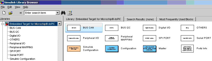
Fig. 13 Blocks installed library "Embedded Target for Microchip dsPIC".
To compile Simulink models together using Matlab and MPLAB, you need to set the path to the MPLAB directory with the MplabOpenModel.m, MplabGetBuildinfo.m and getHardwareConfigs.m files in the Matlab path variable with the highest priority:
>> path('c:\Program Files (x86)\Microchip\MPLAB IDE\Tools\MATLAB\',path) Installing the MPLAB compiler
MPLAB compilers are on the Microchip website (Download Archive → MPLAB C Compiler for PIC24 and dsPIC DSCs). To install the demo version of the C30 compiler, you need to download it via the link PIC24 / dsPIC v3.25 (Fig. 14) and run the received file mplabc30-v3.25-comboUpgrade.exe.
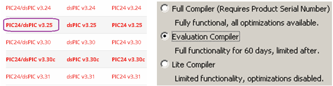
Fig. 14 Compiler C versions (left) and its installation modes (right).
Note. Work performed with the version v3.25 of the C30 compiler for PIC24 / dsPIC. The audit showed that the next version of v3.30 does not support the joint compilation of Matlab R2012a models (dsPIC Toolbox) without errors.
The installation exe file creates in the section c: \ Program Files (x86) \ Microchip \ a new directory mplabc30 with files:

Fig. 15 C30 MPLAB Compiler Directories.
Simulink Programming Sequence for PIC Controllers
1. Create a working directory and copy into it the * .mdl examples from the example section (see. Fig. 12).
2. Download Matlab. Set it to the working directory.
3. Include the path to MPLAB - the directory c: \ Program Files (x86) \ Microchip \ MPLAB IDE \ Tools \ MATLAB \: in the Matlab path variable with the highest priority:
>> path('c:\Program Files (x86)\Microchip\MPLAB IDE\Tools\MATLAB\',path) Note: Using the >> path command with no arguments results in a list of paths to the path variable in the Command Window. You can remove the path from the path variable with the rmpath command, for example:
>>rmpath(' c:\Program Files\Microchip\MPLAB IDE\Tools\MATLAB\') 4. Create a Simulink model for the PIC controller using the “Embedded Target for Microchip dsPIC” library blocks (Fig. 13), or load a ready-made model, for example, Servo_ADC.mdl.
The type of controller for which the Simulink model is developed is selected from the list in the Master> PIC block (Fig. 16, Fig. 10), which should be included in the model.

Fig. 16 The choice of the type of controller in the master block model.
5. Check the model configuration settings: Menu → Simulation → Configuration Parameters <Ctrl + E>. The S Generator compiler dspic.tlc should be specified in the System target file entry line of the Code Generation section (Figure 17). Selecting dspic.tlc adjusts all other model configuration parameters, including the step and integration method.
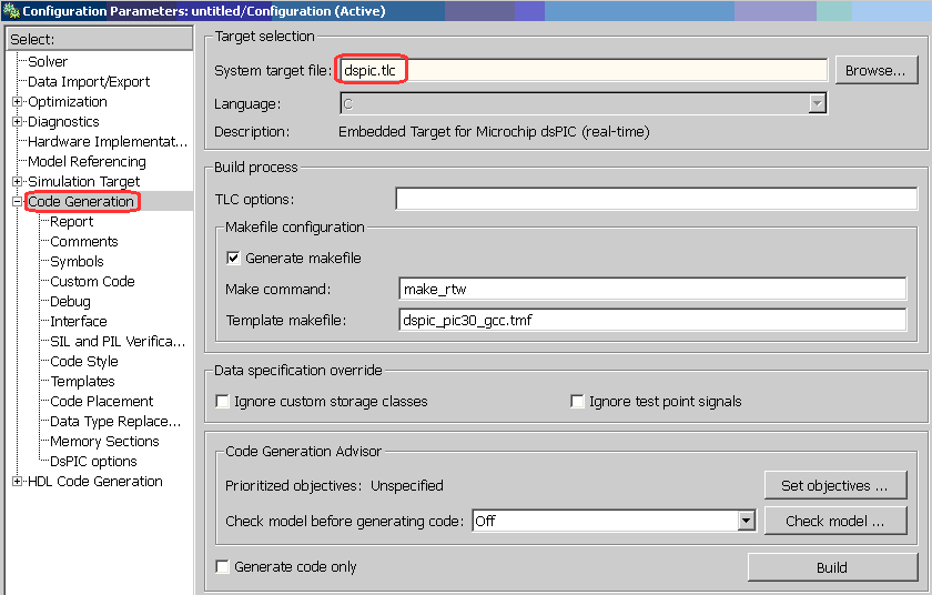
Fig. 17 Select the S-functions compiler dspic.tlc for PIC controller models in the section “main menu → Simulation → Configuration Parameters → Code Generation”.
6. Compile the tmp_Servo_ADC.mdl model. The launch of the compiler is shown in Fig. 18.

Fig. 18 Run the simulink compiler model.
As a result of a successful compilation (message: ### Successful completion of build procedure for model: Servo_ADC), a HEX file is created in the current directory for the firmware of the PIC controller and the MCP MPLAB environment project (Fig. 19).

Fig. 19 The results of compiling the model.
The launch of the model in Matlab / Simulink is performed in the model window with a button, the conditional simulation time is set in the line:

Managing the compilation of Simulink models from MPLAB
The compilation of the Simulink model can be controlled by the commands of the Matlab / Simulink section of the MPLAB environment, for example, in the following order.
1. Develop a PIC controller model in Matlab / Simulink. Save the model.
2. Run MPLAB.
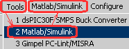
3. Select MPLAB menu → Tools → Matlab / Simulink and the new section will appear in the menu.
4. In the Matlab / Simulink section, open the Simulink model, for example, Servo_ADC, with the command “Matlab / Simulink → Specify Simulink Model Name → Open → File name → Servo_ADC.mdl → Open”. The Open command launches Matlab and opens the model.
5. Compile the model and create a MCP project using the Generate Codes or Generate Codes and Import Files commands. The translation of the MDL model into the MCP project is performed by the TLC Matlab compiler.
As a result, the MPLAB project is created:

with scripts of the model in the C language.
6. Open the project: menu → Project → Open → Servo_ADC.mcp (Fig. 20).

Fig. 20 The structure of the MCP project Simulink model Servo_ADC.mdl in the MPLAB environment.
The Simulink model project is ready for editing, debugging, and compiling into machine controller codes using MPLAB.
Connecting the PIC-KIT3 programmer
You can find out which programmers write a binary code to a specific microcontroller in the menu section → Configure → Select Device of MPLAB 8.92 environment. For example, the PIC-KIT3 programmer does not support the PIC12C508A controller (Fig. 21, left figure), but works with the PIC12F629 controller (Fig. 21, right figure).

Fig. 21 . The list of programmers for microcontroller firmware.
Information about the installed PIC-KIT3 programmer driver can be requested from the Windows device manager (Fig. 22).

Fig. 22 Information about the installed driver for the PIC-KIT3 programmer.
The connection diagram of the PIC12F629 microcontroller to the PIC-KIT3 programmer is shown in Fig. 23.

Fig. 23 . Wiring diagram of the PIC12F629 microcontroller to the PIC-KIT3 programmer.
The PGM output of the programmer for the PIC12F629 controller firmware is not used. The presence of PGM output for different types of PIC controllers is shown in Fig. 24. PGM output is recommended to “pull” to the common wire (GND), through a resistor, with a rating of 1K [3].

Fig. 24 Conclusions PGM PIC controllers.
An indication of the LEDs of the Olimex PIC-KIT3 programmer is shown below:
Yellow - Red - Programmer Status
On - Off - Connected to USB line
On - On - Interaction with MPLAB
Flashing - Always on - Microcontroller firmware
Do not connect the power of the microcontroller VDD (Fig. 23) to the programmer if the controller is powered from its power source.
When powering the microcontroller from the programmer on the VDD line, it is necessary to set the operating voltage, for example, 5V by the MPLAB program (Menu → Programmer → Settings → Power), as shown in Fig. 25
Note. If there is no voltage on the VDD MPLAB IDE line, the following error message is displayed: PK3Err0045: You must connect

Fig. 25 Setting the voltage VDD on the programmer PIC-KIT3 program MPLAB IDE v8.92.
If the programmer cannot set the required voltage, for example, 5V when it is powered by USB, in which the voltage is less than 5V, MPLAB IDE gives an error message: PK3Err0035: Failed to get Device ID. In this case, you must first measure the voltage of the programmer - read it in the menu tab → Programmer → Settings → Status, and then set the voltage (not more than measured) in the menu tab → Programmer → Settings → Power.

Fig. 26 Measurement (left) and setting (right) VDD voltage of the PIC-KIT3 programmer with MPLAB IDE v8.92 program.
An example of an MPLAB message for a successful connection of a microcontroller to a programmer using the menu command → Programmer → Reconnect is shown in Fig. 27.

Fig. 27 . Message MPLAB about the successful connection of the microcontroller to the programmer.
It is possible to program not only a separate PIC controller, but also a controller that is part of the working device. To program the PIC controller, it is necessary to provide for the installation of jumpers and current-limiting resistors as shown in Fig. 28 [3].
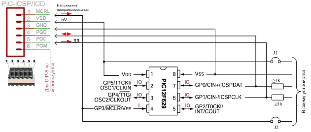
Fig. 28 Connecting the microcontroller in the electronic device to the programmer.
Conclusion
Small-bit PIC controllers have a wide power range, low consumption and small size. They are programmed in low level languages. Development of programs in the Simulink graphical programming language using multiple libraries significantly reduces development and debugging time in comparison with programming at the assembler level. Structures developed for Simulink PIC controllers can also be used for computer simulation of dynamic systems involving controllers. However, due to code redundancy, this approach is applicable only to families of PIC controllers with sufficient resources.
Bibliographic list
1. PIC12F6XX . Single-chip 8-bit FLASH CMOS microcontrollers from Microchip Technology Incorporated. PIC12F629, PIC12F675. OOO “Micro-chip”. Moscow - 2002.
2. Microchip. MPLAB IDE. User's Guide with MPLAB Editor and MPLAB SIM Simulator
3. ICSP - In-Circuit Programming of PIC Controllers DOC Rev 1.03 (last updated 05/19/2005)
4. MPLAB IDE Help: MATLAB.
5. Introduction to Microchip-SIMULINK Blocksets and MATLAB Plug-in for MPLABIDE Produced by Murali Manohara Chembarpu .
6. Embedded Target for 16 bits PIC .
7. Dr. Bob Davidov . Portal of scientific and practical publications
Source: https://habr.com/ru/post/321542/
All Articles