On the question of the history and the role of the personality in it (not according to Plekhanov)
Max Wayne, Mr. Hewlett and rainy Sunday afternoon.
The preface of the translator is, in general, not a very frequent case when I feel a burning envy of the author and annoyed that I was not born where I should have been and not when I should have. I hope many Habr's readers will experience at least the first half of these feelings while reading this truly delightful article and will be lenient with the flaws in translation. I unfortunately cannot put a link to the original as it should be for translation, since the article is included in the absolutely amazing book “Analog Circuit Design: Art, Science, and Personalities”, where I took it, I will not tell you, but I hope You guessed where you can find it.
Well, now the actual translation. There will be pictures, but not to attract attention, but simply without them in any way.
One rainy Sunday afternoon, I found that I had nothing to do. I always liked rainy sundays, which give a lot of free time. So I wandered to my lab (a real house is impossible without a lab).
I ran a look at several dummies in varying degrees of inoperability and several recently purchased powerful transistors that should be removed from the eye out. They did not inspire me at all. Lazily looking around, I noticed the tool repository. On the left, on the third shelf, was the HP Series 200 generator (a real lab is impossible without this generator, see Fig. 1).
')
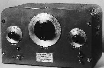
HP200, directly based on the dissertation of HP co-founder William R. Hewlett, is not only a great device. And this is not just the first HP product (1). This device is history itself. He laid down the direction, methods and standards with which HP products are still responsible. This is a fundamental integrity of the device, a sense of reliability and integrity. This small box is an outstanding blend of elegant theoretical ideas, well thought out design, careful design, careful production and capitalism. He perfectly met the requirements of the market. The benefits from it were terrific, and equally shared between the firm and the buyers. As my mom used to say, the HP 200 is made exactly the way things should be done - the good guys win and no one loses.
Delving into the library (a real laboratory is impossible without a library), I found a copy of Stanford's thesis in 1939 by William R. Hewlett "A new type of resistive-capacitive generator" (a real library is impossible without this article).
Hewlett briefly formulated the objectives of the thesis (except for obtaining a degree): “The author believes that there is a real need for a new type of generator, which will combine the stability of LC-generators with the flexibility of generators with frequency transfer, while remaining light, portable and easy to design and configure ".
Hewlett's generator used a resonant RC circuit, invented by Max Vin in 1891. Vin did not have electronic amplifying devices (De Forest in 1891 did not even think about adding a grid to Edison's lamp) so he could not create a generator. In any case, Win dealt with other problems and developed his own circuit for bridge measurements on alternating current.
Hewlett saw that the Vina Bridge, in combination with appropriately controlled electronic amplification, provides significant advantages over the previously used methods for constructing generators. This is an extended tuning range, frequency and amplitude stability, low distortion and simplicity.
Hewlett had something else besides electronic amplifiers available: he had new approaches in feedback theory. The reference to the pioneering work of Harold C Black “Stabilized Feedback Amplifiers” is in the fourth line of the bibliography. Similarly, Nyquist's Theory of Regeneration, the classic description of the conditions necessary for generation, is on the third line.
Hewlett used all of the above to show that the Wine scheme can be used for generation. Then he added the only (absolutely literally) critical element.
To obtain stable sinusoidal oscillations, the generator gain must be carefully controlled. If amplification is not enough, generation does not occur. If it is redundant, the amplitude of the oscillations increases and the output signal becomes rectangular. The task is to introduce an amplitude adjustment mechanism that does not introduce noticeable distortion in the waveform.
Hewlett offers an elegant solution:
“The last requirement, an amplitude limiting device that does not introduce distortion in the output signal, is quite difficult to fulfill. It is known that the gain of an amplifier with OOS is 1 / b, subject to A * b >> 1. Therefore, if the resistance, the value of which increases with increasing current through it, is used in the OOS circuit, the amplifier can be designed so that its gain decreases with increasing input signal. If an amplifier of this type is used as part of a generator, its gain can be adjusted so that generation just begins.
When the amplitude of oscillations begins to increase, the amplification decreases, which will lead to stabilization of the amplitude of oscillations at a certain level. If this value is low enough, the lamps will work in class A and do not introduce large distortions. Moreover, any distortions due to the non-linearity of the IV characteristics of the lamps will be reduced by A * b times due to the action of environmental protection.
As a variable resistance, you can use a small incandescent lamp. A well-known property of such a lamp is heating the filament with an increase in the current through it, which leads to an increase in the resistance of the filament. Figure 2 shows the dependence of the resistance of the lamp 110 volt 6 watts on the current through it.
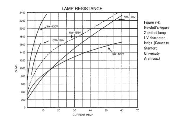
Obviously, the maximum degree of change in resistance is achieved at currents less than 20 ma, and the lamp must work in this area to obtain the maximum stabilizing effect. In fig. 3 shows the complete generator circuit.
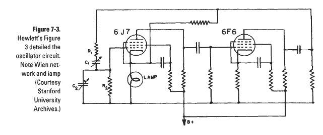
The signal OOS is removed from the anode of the output lamp and is fed to the cathode of the input lamp. Incandescent lamp is installed between the cathode and the ground, so that the depth of the OOS increases and the gain decreases with increasing amplitude of oscillations.
The only requirement for the lamp is that it operates at such a temperature that its thermal time constant is much more than half the period of the minimum generation frequency. Since thermal radiation is proportional to 4 degrees of absolute temperature and most of the energy is dissipated by radiation, this requirement is easily fulfilled by prohibiting the use of large currents. In this case, the lamp life is almost endless. ”
The use of an incandescent bulb by Hewlett is elegant due to the simplicity of the solution 2). More importantly, it is an excellent example of deep thinking. The problem as a whole was considered as complex, not only from the point of view of electronics. And this is a sign of excellent problem solving and good engineering.
The lamp solved a complex problem completely, creating the conditions for building a practical device. The development was very good. The generator covered the range from 20 to 20,000 cycles (then there were cycles, not Hertz) in three decades with a calibration accuracy of 1%. Incandescent bulbs ensured amplitude stability of 0.2% per 100 Hz and non-uniformity of 1 dB in the range from 20 to 20,000 cycles. Looking inside my HP201, I saw an incandescent lamp exactly where Hewlett or one of his assistants had left it.
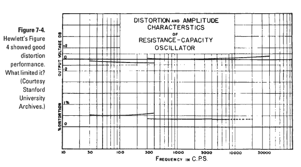
From Fig.4 it is seen that the generator distortions do not exceed 0.5% in the whole range. This chart caught my attention. According to modern standards, the “operational amplifier” of Hewlett on 6J7 / 6F6 lamps has very poor parameters 3). I wondered how good the Hewlett circuit would be on modern op amps?
And now, 50 years after Hewlett made his generator, I assembled a generator on a breadboard to fill this rainy Sunday. My diagram is shown in Fig. five.
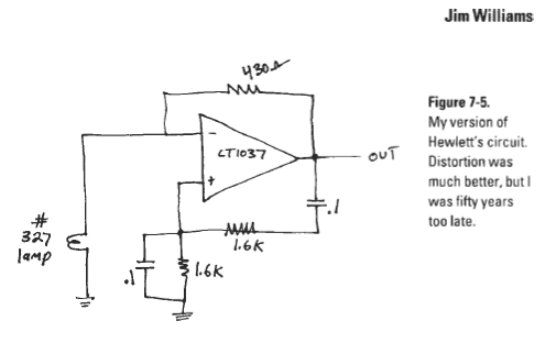
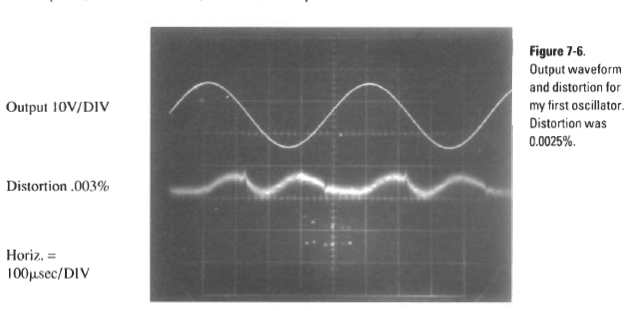
The circuit coincides with the Hewlett circuit, except for the fact that I used 94 monolithic transistors, a resistor and a capacitor instead of two lamps 4). (I think this means progress). After selecting the resistor 430om scheme gave a nice sine. Having connected my (HP) distortion meter, I observed with great pleasure only 0.0025% distortion. - rice. 6
Then I went further and added the switching of the pic ranges. 7
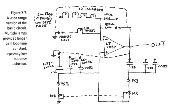
This scheme also worked well. As Hewlett warned, the distortion increased as the oscillation frequency approached the lamp thermal time constant. This effect can be reduced by increasing the thermal constant. The easiest way to do this is to add more and bigger lamps. This leads to an increase in stabilization time, but reduces distortion in the steady state. The graph of the dependence of the distortion of the frequency of this clearly shows -cm. rice 8.

Looking at this graph, I wondered how much distortion figures could be improved using Hewlett’s hypotheses and results as a guide. An experiment using several lamps showed that the growth of distortion at low frequencies almost completely is determined by the thermal time constant of the lamp. But what caused a slight rise in distortion in the 15-20kHz area? And what limits the reduction of distortion? Figuring out all this to the end is a great way not to fall under the rain. And of course, I could not ignore the fact that I am very close to the sensitivity threshold of my analyzer 0.0018%. Do not worry.
The following diagram is shown in Fig. 7-9.
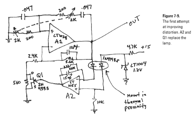
A1, low-noise broadband amplifier is a generator. The reduced nominal of the variable variable allows to obtain a low noise level by reducing the contribution of the noise of the input current of the OU. A 10 pF capacitor suppresses parasitic high-frequency generation. A2 and the components around it replace the incandescent lamp (s). A2 compares the peak output voltage of the generator with the reference voltage and controls Q1 to obtain the desired gain. A diode in series with a reference voltage compensates for a drop in a rectifier diode. A large capacitor in the A2 OC circuit allows a large time constant to be obtained, minimizing the output pulsations.
When I turned on this scheme, it generated, but the distortions increased to a monstrous 0.15%! The analyzer output showed a pronounced second harmonic (twice the oscillator frequency), although the A2 output looked relatively clean - see fig.10.

So, I got away with replacing 2 lamps with 94 transistors, a capacitor and a resistor, but replacing one incandescent lamp with a bunch of parts is another matter! I looked at the abandoned incandescent lamp in confusion.
What happened? Wien Bridge has remained the same, and it is hard to believe that A1 is so bad. At output A2, the residual ripple of the rectifier was visible, but nothing that could provoke the appearance of such a monster.
Guilty was Q1. The FET channel resistance is ideally determined by the gate-channel voltage. In reality, there is a slight modulation of the channel resistance when the drain-source voltage changes. Unfortunately, drain Q1 is under considerable alternating voltage. At the gate almost constant voltage, the source is grounded. This causes undesired modulation of the amplitude stabilization loop, leading to distortion. A simple incandescent bulb began to look more and more attractive.
If you look at the scheme for a long time, you will see that the necessary medicine exists in the scheme itself and it (thank God) is quite simple. The FET is a symmetrical structure, although in this circuit the control voltage is applied asymmetrically from the gate to the source. If you change the circuit so that the gate is controlled by a signal equal to half the drain-source voltage, the symmetry will be restored. This innovation eliminates all even harmonics. The new switching circuit Q1 is shown in Fig.11.

When trimming the trimmer to the optimum position, the distortion fell to 0.0018% - the lower limit of the analyzer according to the specification of fig.12.

Hoping that my analyzer is better than what is indicated in its specification, I looked, as evidenced by its output signal. We see some influence of the first harmonic and artifacts associated with the ripple of the rectified voltage of the AGC loop. Reduce the first harmonic by adjusting the resistor, although increasing the rectifier ripple can be reduced by increasing the A2 integrator time constant.
I do not like podstroechniki, and the electrolyte in the chain of OOS A2 looks too big. Also, the A2 is not a true integrator and has noise amplification from a non-inverting input. It looks more annoying than obviously important. It is also unpleasant that if the output A2 is positive (for example, when turned on), the electrolyte will be back shifted. This is irrelevant but a bad style!
The next iteration of the scheme is an attempt to solve some of these problems, see fig.13.
The most significant change - Q1 is replaced by a photoresistor. This device has no parasitic modulation of resistance, which eliminates the trimmer from the circuit. The A2 is powered by a unipolar source and is included as a true integrator. The ratings of the components in the integrator's OS chain are changed in an attempt to obtain a larger time constant and a shorter settling time. Finally, the integrator's reference voltage is increased to increase the effect on the amplitude of the output signal. This is a famous brute force method for increasing SNR.
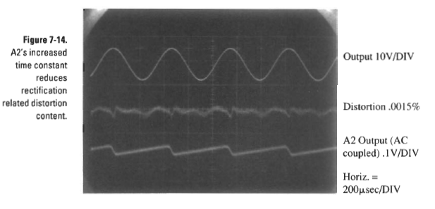
This experiment gave useful information - see fig. 13.

Modification A2 excluded the passage of rectifier pulsations. The photoresistor actually worked, and I threw the trimmer into the far corner. The analyzer showed 0.0015%, but I was not sure that I could take this “improvement” seriously. Interestingly, the second harmonic of distortion looked the same as in the previous scheme, perhaps less noisy. It increased slightly with increasing frequency and was more or less proportional to the output amplitude. The analyzer gave a figure of a few ppm (ppm) lower with a larger output amplitude, but I decided that this was due to the SNR in the generator, the analyzer, or both.
But it became clear that the key to squeezing everything possible out of this scheme is to understand the source of the second harmonic. The scheme told me about something, I tried to hear, but did not hear fig.14.
All previously made excluded from suspicion the AGC loop. There remained a bridge of Vina, A1, and parasitic elements not present on the scheme, as the main suspects.
I considered a possible change in the Vinh bridge elements — the voltage coefficient of the resistors, the ESR, and the dielectric absorption of the capacitors. Sometimes, if you do not know how to do something better, you can understand a lot by doing something worse. Therefore, I added small controlled parasitic RC circuits to the elements of the Wayne bridge to check the sensitivity of the circuit to the parasitic components and to the non-ideality of the components. I realized that relatively good resistors and capacitors were not the source of the problem. Different versions of the Wayne bridge components of acceptable quality led to the same results.
It seems to be the only culprit - A1. The gain of the OS without the OS, decreasing with frequency, could be a problem, so I decided to add an output buffer to unload the OS. This was the only thing I could do to increase the gain.
Now that I had an A1 arrest warrant, the answer quickly became apparent. My scheme violated the little-known principle of constructing precision circuits at the OS: the Williams rule. Williams rule is simple: ALWAYS INVERT (except when you absolutely can't). This rule, proclaimed after countless wars with bizarre, incomprehensible and intractable effects in numerous schemes, was invented to eliminate the slippery results of non-ideal suppression of common-mode voltage in the OS. The effect caused by common-mode voltages is often difficult to predict and detect, let alone correct. The zero point summing point is a very friendly, very reliable place. It is (usually) predictable, mathematically comprehensible and invulnerable to insidious common-mode dragons.
For all existing op amps, the common-mode voltage rejection ratio (CMRR) decreases with increasing frequency, and A1 is no exception. The graph of CMRR versus frequency is shown in Figure 15.

In the generator circuit at the inputs of A1 there is a large common-mode voltage. Since CMRR falls with increasing frequency, it is not surprising that I have seen some increase in distortion at high frequencies. This seemed at least as a plausible explanation. Now I had to test this idea. To do this, it was necessary to bring the scheme into conformity with the Williams rule. Linking the non-inverting input A1 to the ground looks like an unnecessary sacrifice for our scheme.
I considered various strange schemes for solving this problem. One of these horrors is the separation of the Vina Bridge and the A1 entrance through a transformer. This approach is not just ugly, it is likely that in certain places it will be recognized as obscene. I didn’t even begin to draw such a scheme so that the publisher of this book couldn’t bring a group of OU-fundamentalist fans to the court.Even if I made this ungainly scheme work, I just felt that it was impossible to do that. I could almost hear the simple, small, elegant Hewlett incandescent bulb that worked so well laugh at me.
Somewhere in the respected Philbrick Application Guide, it says: "There is always a way out." The last diagram shows what it is - fig.16.

This scheme is similar to the previous one, with the exception of A3, which appeared along with buffer A4. A3 binds the non-inverting input A1 to the virtual ground by moving those nodes of the Wien bridge and the AGC scheme that were previously tied to the ground. By this we add the third control circuit to the original Hewlett scheme (it will be a very busy generator - poor unfortunate A1, servant of three masters), but we do not have a negative impact on his work. When the non-inverting input A1 is tied to virtual earth, there is no common-mode component at its inputs. The scheme began to satisfy the rule of Williams, and, most likely, good things should begin.
To my great amazement, this whole thing didn't explode when in the end I pulled myself together and turned on the power. But even more striking was that the analyzer showed 0.0008% distortion - fig. 17
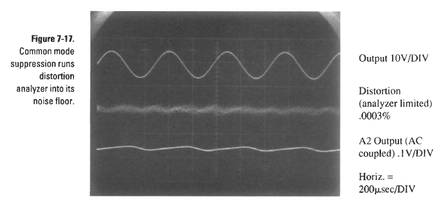
At the output of the analyzer, only the weak trace of the first harmonic and noise is visible. The analyzer showed values two times smaller than the lower measured distortion threshold according to the specification that delivered. Although it is unlikely that the generator and the analyzer would have compensating errors, it was early to draw conclusions. And I decided to turn to very specialized equipment to find out the truth. I took the generator to Audio Precision System One, where the distortions were measured and they were 0.0003% (3ppm or -110db).
I was very pleased that we could not find anything higher than this level.
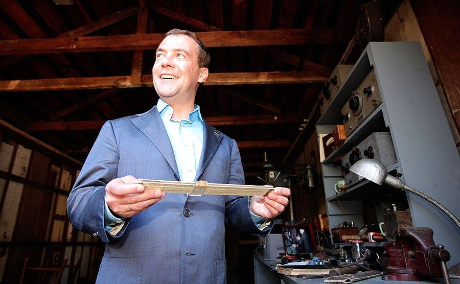
After Hewlett had finished his generator, they, together with David Packard, went to the garage and collected some more pieces there, and then made several different measuring devices - see figure 18.

After I finished my generator, I went to the kitchen and made some hot dogs for lunch (mustard, chili sauce, no beans), and then all sorts of different foods. So, Hewlett was not only much smarter than me, he also had other priorities. However, when ultimately he had to go to dinner, I think he had a wonderful appetite. And my hot dogs tasted very good.
1) In addition, by the way, their longest-living product. The HP2000 series continued to be sold until the mid-80s, almost 50 years.
2) Hewlett borrowed this technology from Meacham, who offered it in 1938 as a way to stabilize a quartz oscillator. The relevant work is given in reference number five to the thesis.
3) From the standpoint of those years, 6J6 and 6F6 are thermionic FETs, developed by Lee De Forest.
4) To be precise, 50 transistors, 40 resistors and 4 capacitors in this circuit.
From the translator - well, in conclusion, purely for laughter, another picture from the same garage - I swear, it lies in this form on the official website, I did not retouch it.
Source: https://habr.com/ru/post/321146/
All Articles