Basics of computer networks. Subject number 7. Spanning Tree Protocol: STP
Welcome to the next article on the basics of computer networks. Today we will touch on yet another family of protocols in the switching world. And today we will talk about spanning tree protocols or STP. We learn how to build this tree, how to manage it, what loops are, how to deal with them. The topic is interesting, so I invite you to read more.
Content
1) Basic network terms, OSI network model and TCP / IP protocol stack.
2) Top-level protocols.
3) Protocols of lower levels (transport, network and channel).
4) Network devices and types of cables used.
5) The concept of IP addressing, subnet masks and their calculation.
6) The concept of VLAN, Trunk and VTP and DTP protocols.
7) Spanning Tree Protocol: STP.
8) Channel Aggregation Protocol: Etherchannel.
9) Routing: static and dynamic on the example of RIP, OSPF and EIGRP.
10) Network Address Translation: NAT and PAT.
11) Reservation protocols for the first transition: FHRP.
12) Computer network security and virtual private networks: VPN.
13) Global networks and protocols used: PPP, HDLC, Frame Relay.
14) Introduction to IPv6 configuration and routing.
15) Network management and network monitoring.
PS Perhaps over time, the list will be added.
Long thought where to start. In an amicable way, one must begin with a theory. But it makes sense to understand the protocol when I have not yet encountered a problem that this protocol can solve. Therefore, I decided to start with a little practice and show what you can immediately stumble over. Next, deal with this problem and show what to do next. I will collect the most common scheme.
')
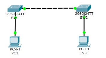
There are 2 computers and 2 switches connected to each other. The address for PC1-192.168.1.2, and for PC2-192.168.1.3. Computers communicate with each other, send something to each other. But we notice a weak spot.
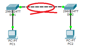
If a cable breaks, participants will be left without communication. And the very first thought that comes to mind is to plug another cable. But the first thought is not always true. The pictures do not show it, so I will show it in the form of animation.
Switching loop
I think they noticed how strangely the links flashed in sync. This phenomenon is called a loop. To learn more about it, you need to go into simulation mode. Open the spoiler below and admire.
Commutation loop in simulation mode
I will explain in more detail. So PC1 decides to send an ICMP packet to PC2. As a rule, before you start sending, you need to know its MAC address, and it starts ARP. We remember how switches work with ARP. They send it to all ports, except outgoing. What happens to us?
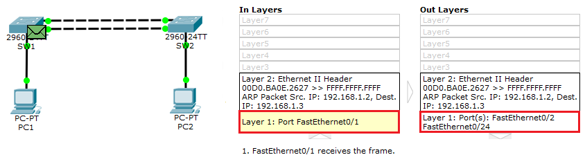
The switch, according to its logic, sends ARP to both ports (fa0 / 2 and fa0 / 24). But does not send it to fa0 / 1.

SW2 will do the same. He will send the ARP that he received from port fa0 / 24 to the active port fa0 / 2. And the second ARP received from port fa0 / 2 will be sent to fa0 / 24. It would seem that we have already received ARP from the 24th port. But here is the nuance. We received ARP from another port and a separate ARP message. Therefore, for the switch, these are 2 different frames and are processed independently of each other. Well, then by analogy. SW2 will send one of the ARPs back to SW1, and that, in turn, will send back SW2. And he will walk like this indefinitely until the cable is pulled out or until the switch “drowns” with frames and stops responding. This is the loop. Accordingly, the more switches, the more frames will be created, which will lead to a rapid network failure. Therefore, by increasing the redundancy of connections, we increase the probability of getting loops. Who is interested to see this flicker on your computer, download from here .
Understood the leading minds that this is bad and must be fought with. This task was laid on the shoulders of an outstanding engineer Radia Perlman (Radia Joy Perlman) in 1985. What is the essence of its technology. You have an N-th number of switches connected to each other. And before transferring user data, they negotiate among themselves for the right to become a root switch or “root switch”. The remaining switches leave only those interfaces that lead to the root switch, and the rest off. Thus, each switch can be reached only in one way. Let us analyze this process in more detail.
We have 3 switches connected to each other.
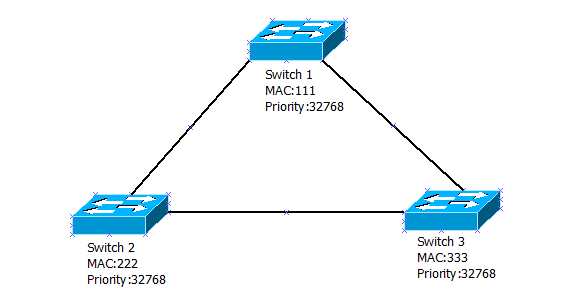
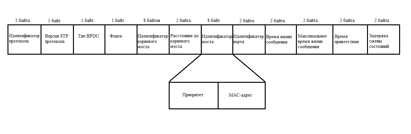
I conditionally gave them names and MAC addresses. Each switch includes the classic STP protocol (let's talk about the others below). As I said above, they need to determine which of them will become the root switch. To do this, they begin to exchange BPDU frames. Let's see what this frame is.
If it is hard to see, you can click on it and the original image will open (open the image by pressing the mouse wheel, or right-click on “Open link in new tab”, so as not to close the article itself).
A lot of incomprehensible fields. We will get acquainted with them and we will put all this porridge in order.
- Protocol Identifier is a 2-byte field that is always zero.
- The version of the STP protocol (Protocol Version Identifier) is a field the size of 1 byte, the value of which is always equal to "0".
- BPDU type (BPDU type) - 1 byte, which is “0” if it is a configuration BPDU (CBPDU), or “1” if it is a TCN BPDU.
- CBPDU (Configuration Bridge Protocol Data Unit) - a frame used to calculate the spanning tree. That is, when the value = 0.
- The TCNBPDU (Topology Change Notification Bridge Protocol Data Unit) is a frame used to notify others about changes in the topology. That is, when the value is 1. Simply put, if the switch sees what has happened, some change in the topology (the link has fallen off, the neighbor has died, etc.), it starts up a BPDU with a value of “1” in the BPDU field Type. And then frames with the value “0” work to rebuild the tree.
- Flags — Only 1 byte is used in this field. These flags are used when changing the topology (bit "1") and confirming the topology (bit "8").
- Root Identifier — This field contains information about the root switch, namely its priority and its MAC address.
- Root Path Cost - this is the total cost to the root switch. I will give a sign where the cost is indicated.
Channel speed Cost of 10 Gbps 2 1 Gbps four 100 Mbps nineteen 10 Mbps 100
This table is modified. Previously, the cost was considered differently, but with the advent of new speed standards, the previous specification has lost its force. - Bridge Identifier - here the sending switch records its data (priority + MAC address).
- Port Identifier - here the sending switch records the port identifier (that is, the one from which this BPDU comes out).
- Message Age - this is the time interval (in seconds). It is needed in order to recognize obsolete frames and discard. It is formed by the root switch and sets to the initial value "0". Next, each subsequent switch increases this value by the delay time. As soon as this value exceeds the maximum threshold value, it will be discarded.
- Maximum message lifetime (Max Age) - this field is responsible, just for the maximum lifetime. Exceeding it, the switch drops the frame.
- Hello Time — The time interval at which the switch sends BPDU frames. The default is 2 seconds.
- Forward Delay - a time interval that indicates how many seconds the switch port will be in the listening and learning state.
This is the standard set of BPDUs in STP. Depending on the version, the fields may be called differently, but the principle of their work is the same. The frame itself is large and on the move can not immediately keep everything in my head. This is normal. Know all the fields by heart is not required. The main thing that needs to be firmly understood within the CCNA framework is fields 5, 6, 7 and 8. Therefore, we proceed to the analysis of the operation of the STP protocol.
In many editions of "ciskovsky" and third-party, the work of STP is shown on the example of 3 switches connected to each other. I will not depart from the tradition and will do likewise.

Conventionally, I gave them the names and MAC-addresses, so as not to litter the head with a long addressing. Moving on.
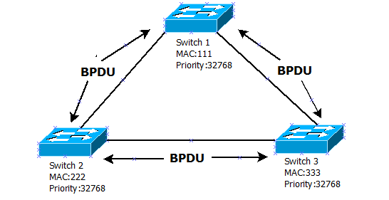
And since the STP protocol is working on the switches, they need to choose who will be the main one in the topology or the root one . For this, they begin to exchange BPDU frames. This is where fields 5, 6 and 7 are important. I specifically want to dwell on them. Initially, switches in field 5 (Root Bridge Identifier or Root Identifier) begin to write their “priority + MAC address”. If you manually change nothing, then the priority is 32678. Next, the switch that receives this frame from the neighbor will compare its Root Identifier with the newcomer. If he sees that his neighbor has this Root ID lower, then from that moment he will relay his BPDU. As a result, only one switch will remain in the network, which will generate BPDUs.
In field 6 of the Root Path Cost, the switch records the cost of the path. When creating a BPDU, the root switch writes 0 to it, since this is it. But the following switches are already beginning to summarize the cost of the table presented above.
Well, in the field 7 "Bridge Identifier" a bunch of "priority + MAC address" of the switch itself is recorded. That is, if the bundle of the root switch is always written in the Root Identifier, then in this field, it always writes its own. That is, when relaying BPDU from neighbor to neighbor, switches add their Bridge ID here.
I will say a few words about the “priority + MAC address” bundle. They are not summarized in any way. I inserted the plus sign in the context that they always work together. At first, switches, when holding elections, look at priority . And if priorities are equal (and by default they are equal), then it starts relying on MAC addresses. And the one who has less MAC-address becomes main, root or root. Call as you like. That priority is needed just to administratively influence the choice of the root switch. Imagine the situation that you have 2 switches. One of them is new and productive, and the second is old, ancient and will soon be written off. And it turns out that the old switch has a MAC address less than the new switch, which means that with equal priorities, the old switch will always win. It is to solve such a controversial problem that priority is needed. Moreover, when you change the priority, it must be a multiple of 4096 (that is, 32768, 28672, 24576, and so on). We return to the scheme.
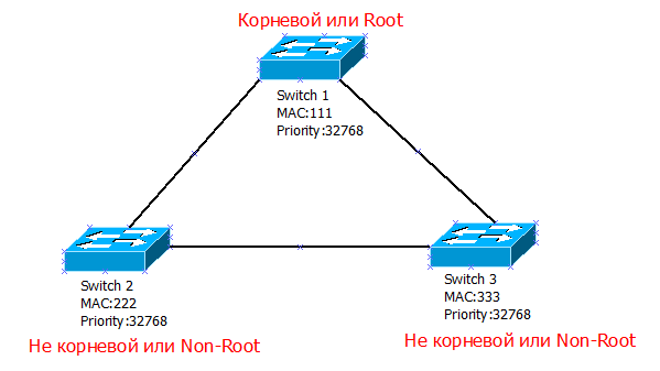
Well, since the priorities of the three switches are the same, they start the elections by MAC addresses. The lowest MAC address of Switch 1 => it becomes root.
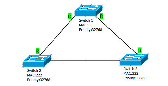
Since Switch 1 becomes root, it immediately transfers all its interfaces to the “Designated” mode. That is, it is the port that has the shortest path to the root switch (in this case, to itself).
Further Switch 2 and Switch 3 must decide for themselves which port will be the root. That is, the port that has the lowest cost path to the root switch. Everything is obvious here. If it suddenly turns out that the cost of several ports is the same, then he will choose the port with the lowest sequence number or name. For example, fa0 / 1 will be selected from ports fa0 / 1, fa0 / 2 and fa0 / 3.
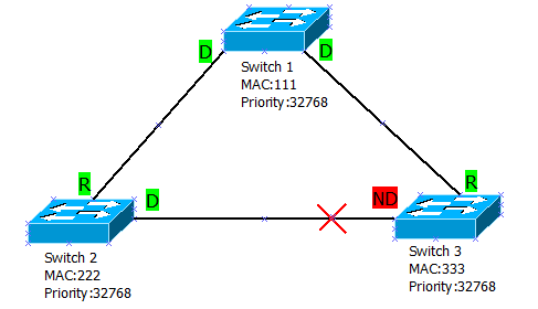
Root ports are defined, but what to do with the link between Switch 2 and Switch 3, because it can create a loop? To prevent it, they agree on which of them will disconnect their port.
They will also agree on the Bridge ID. Priorities are equal, so we look at the MAC-addresses. Switch 2 has a smaller MAC address, so it switches the port to Designated mode, and Switch 3 to Non-Designated mode. “Non-Designated” is a mode in which the port is prohibited from transmitting any data, but is allowed to listen to what is happening on the network. That is, if a link falls off, it can turn on and work right.
In addition to roles, ports have states that they must pass without fail. I will explain on the example of the constructed topology. Here we have built above tree STP. There are no loops and everything is fine. One of the Switch 3 ports is in the Blocking state. Here he listens to BPDU and does not touch anyone. But if a link suddenly falls off or a topology changes, it immediately goes into the Listening or Listening state. In this state, it sends, listens only to BPDU frames and processes the received information. If he sees that his neighbors have worse parameters than he does, then after 15 seconds, he goes into the next state of Learning or Learning . This phase also lasts 15 seconds. In “Learning,” the port does almost everything the same as in the previous state, except that it now builds a switching table based on the received frames. If after 15 seconds, he does not receive a BPDU with parameters better than his, he will go to the last state Forwarding or Promotion . This is the final and full state. It exchanges not only service information, but also user data. That is, the transition from the Listening to Forwarding state lasts 30 seconds.
There is also a Disable or Disabled state when manually disconnecting a port, but I do not consider this to be an STP state. In this state, nothing will be transmitted. This, roughly speaking, the physical shutdown of the port.
The above example is the work of the classic STP protocol, which is also called CST (Classic Spanning Tree) . One of its downsides is that it builds one single tree for the entire topology. And considering that VLANs appeared, it was necessary to modify this protocol for them. Cisco, as a pioneer, released the PVST (Per-VLAN Spanning Tree) protocol . He allowed to build a separate tree for each VLAN. The only thing that he worked with ISL (proprietary tsiskovsky protocol that works with tagged frames), which was used only on devices of this manufacturer. But with the advent of the open 802.1q protocol, they quickly upgraded PVST and gave it the name PVST + . It works the same as its predecessor, but with 802.1q. I will draw a diagram and explain in more detail.
Here, for example, I have 2 VLANs. And for each VLAN, the PVST + protocol builds a separate tree. In principle, this is its difference from CST. Elections and transitions are similar and with the same time interval. Unfortunately, or fortunately, modern Cisco switches no longer support CST.
Therefore, let's practice PVST +. Moreover, when the network is operating in the same VLAN (which is the default VLAN), it will differ little from the classical STP.
I have quickly assembled the lab from 3 switches and now I’ll show you clearly.
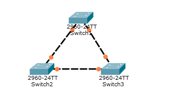
And as soon as the switches go through all the stages, an STP-tree is formed.
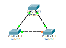
I think you noticed that one of the Switch3 switch ports is orange. This means that this port is in the Blocking state. Do not confuse with Disabled . That is, it does not apply to user traffic, but listens to what is happening on the network. And no matter how much we plug in the cables. The topology will always work out STP and close loops.
Actually, as shown in the figure.
Now I’ll show what happens to the switches when the tree is already built. According to the STP logic, the root switch should send a Hello frame to the “slave” switches with a time interval of 2 seconds.
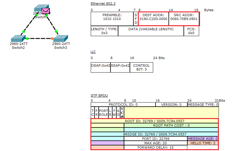
What he is, you see in the picture above. Please pay attention to the field frame Ethernet 802.3. Namely, “Source MAC-Address” and “Destination MAC-Address”. In “Source MAC-Address”, he writes down the MAC address of his port (in this case, FastEthernet 0/1). And in the “Destination MAC-Address” the multicast address is “0180.C200.0000”, which is sent to all participants who know what STP is and work with it. Well, the frame itself is STP BPDU. There are a lot of fields. But I will focus on the more important ones, which I marked with a red rectangle.
- Root ID - 32769 / 0009.7C94.0557. This is, exactly, that very bunch of “priority + MAC address”. But here is an interesting point. If in classic STP, the default priority was 32768, here we see 32769. In the PVST + protocol and others who can work with VLAN, the system ID extension parameter is added to the priority. This parameter contains the VLAN number and, according to it, the switch understands which STP process it belongs to. That is, in this case, we have VLAN # 1 => priority = 32768 + 1 = 32769. If we configured for the 10th VLAN, the priority was 32778. Well, after the fractional line, the MAC address of the interface itself.
- Root Path Cost - the cost of the path. We study the frame when it comes out of the root switch => there is 0.
- Bridge ID — The switch ID that relays this BPDU. It is currently the same as the Root ID.
- Port ID - the port ID. Same as priority - 32769.
- Message Age - time interval. Since the BPDU is “fresh”, it stands at 0.
- Max Age - the maximum lifetime is 20 seconds.
- Hello Time - the sending interval is 2 seconds.
- Forward Delay - indicates how many seconds to be in one phase (listening or learning) - 15 seconds.
In principle, there is nothing new here, and all this we have analyzed above. I showed this in order for you to understand why I had loaded so long with dry text.
We already know who the root switch is and which port is blocked to eliminate the loop. But in the exam and in everyday life we will operate with teams, with the help of which it will be possible to find out who in the segment is the root, from whom the port is blocked and other information. Let's start with Switch1 and with the most important show spanning-tree command. Its important to remember.
Switch1#show spanning-tree VLAN0001 Spanning tree enabled protocol ieee Root ID Priority 32769 Address 0009.7C94.0557 This bridge is the root Hello Time 2 sec Max Age 20 sec Forward Delay 15 sec Bridge ID Priority 32769 (priority 32768 sys-id-ext 1) Address 0009.7C94.0557 Hello Time 2 sec Max Age 20 sec Forward Delay 15 sec Aging Time 20 Interface Role Sts Cost Prio.Nbr Type ---------------- ---- --- --------- -------- -------------------------------- Fa0/1 Desg FWD 19 128.1 P2p Fa0/2 Desg FWD 19 128.2 P2p This command displays information about all STP processes (that is, for each VLAN) in which the switch participates. In our case, only one VLAN. Now let's talk about what these letters mean.
The first thing that catches your eye is the Root ID block.
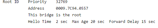
It contains information about the priority, MAC address and timers of the root switch. Here is another important line “This bridge is the root”. It says that this particular switch is the root of the VLAN. Therefore, if you need to find the root switch, then look for this inscription. On the adjacent switch (non-root) this line will not be.
The next block is the Bridge ID .
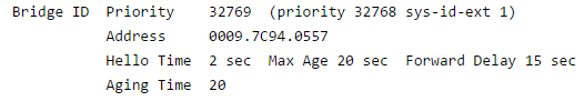
Here, respectively, information about the current switch. On the root switch, this block is identical to the higher one.
Well, below is the table.
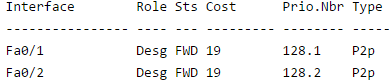
It contains interfaces related to this VLAN, their roles, statuses, and so on. Let us dwell on it.
Since this is the root switch, the ports are automatically transferred to the “Designated” role.
The status “Forwarding” indicates that the ports have passed all stages and are now in active mode (transfer).
Next comes the cost, and it is equal to 19. FastEthernet operates at a speed of 100 Mbit / s and for this speed the cost is equal to 19 (the label is shown above).
Next comes the Prio.Nbr or Priority Number column. This is the port priority. By default, this parameter is 128, and after the dot, the port serial number is recorded. Accordingly, for Fa0 / 1 it is 128.1, and for Fa0 / 2 it is 128.2.
The “p2p” type indicates that the switch port operates in the “full-duplex” mode. This means that the port can simultaneously transmit and receive.
If “shared” is specified there, it will mean that the port is operating in the “half-duplex” mode. That is, he either transmits or receives (not at the same time).
Let's move on to the next Switch2 switch. Similarly, I will enter the command “show spanning-tree” and see what it shows.
Switch2#show spanning-tree VLAN0001 Spanning tree enabled protocol ieee Root ID Priority 32769 Address 0009.7C94.0557 Cost 19 Port 1(FastEthernet0/1) Hello Time 2 sec Max Age 20 sec Forward Delay 15 sec Bridge ID Priority 32769 (priority 32768 sys-id-ext 1) Address 00D0.9776.B743 Hello Time 2 sec Max Age 20 sec Forward Delay 15 sec Aging Time 20 Interface Role Sts Cost Prio.Nbr Type ---------------- ---- --- --------- -------- -------------------------------- Fa0/1 Root FWD 19 128.1 P2p Fa0/2 Desg FWD 19 128.2 P2p Pay attention to the block Root ID .
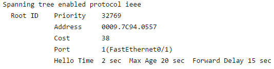
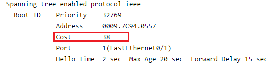
As mentioned earlier, this contains information about the root switch. But there is no longer the inscription "This bridge is the root", since this switch is not the root. But there is another Port entry. It contains the port leading to the root switch, and this is FastEthernet0 / 1. Above is the Cost line and it is 19. Do not confuse this Cost line with the same line in the interface table below. If the cost in the interface table is specified for a specific port, then the total cost to the root switch is recorded here. For example, if there is another switch behind the Switch2 switch with the FastEthernet interface, then its cost will be higher.
That is, he adds up the cost of his interface with the cost of his neighbor's interface.
Moving on and stumble on the block Bridge ID . Here he writes information about himself. You may notice that the MAC addresses are different. Next come the timers. This is an important indicator and try not to forget about it. Better not to change it. But, if you still need to do it, then change and on neighboring switches. Otherwise, it can lead to serious errors and will take quite a bit of time for elimination.
The interface table differs from the root switch in that the FastEthernet0 / 1 role is not “Designated”, but “Root”. That is, this port leads to the root switch.
The last Switch3 switch stayed
Switch3#show spanning-tree VLAN0001 Spanning tree enabled protocol ieee Root ID Priority 32769 Address 0009.7C94.0557 Cost 19 Port 1(FastEthernet0/1) Hello Time 2 sec Max Age 20 sec Forward Delay 15 sec Bridge ID Priority 32769 (priority 32768 sys-id-ext 1) Address 00D0.BA84.7C38 Hello Time 2 sec Max Age 20 sec Forward Delay 15 sec Aging Time 20 Interface Role Sts Cost Prio.Nbr Type ---------------- ---- --- --------- -------- -------------------------------- Fa0/1 Root FWD 19 128.1 P2p Fa0/2 Altn BLK 19 128.2 P2p Here the configuration is the same, with the exception of the FastEthernet0 / 2 port.

He is in the role of Alternate . That is, as a spare. And the Blocking status indicates that the port is blocked in order to “break” the loop. Here is the principle of the classic STP. I attach the link to download this lab.
But this view is not very relevant, as you will not find a serious organization, which has only one VLAN. Accordingly, our task is to make STP friends with VLAN.
Therefore, we create VLANs on each switch. You can, of course, enable VTP and they are automatically synchronized, but I am not a supporter of this protocol. Therefore, in a notebook I prepared a template of commands that I will insert on each switch.
Command list
enable
configure terminal
vlan 2
exit
vlan 3
exit
interface range fastethernet 0 / 1-2
switchport mode trunk
configure terminal
vlan 2
exit
vlan 3
exit
interface range fastethernet 0 / 1-2
switchport mode trunk
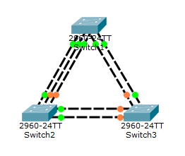
And now I will check what happened at the output with the command “show spanning-tree”.
Switch1#show spanning-tree VLAN0001 Spanning tree enabled protocol ieee Root ID Priority 32769 Address 0009.7C94.0557 This bridge is the root Hello Time 2 sec Max Age 20 sec Forward Delay 15 sec Bridge ID Priority 32769 (priority 32768 sys-id-ext 1) Address 0009.7C94.0557 Hello Time 2 sec Max Age 20 sec Forward Delay 15 sec Aging Time 20 Interface Role Sts Cost Prio.Nbr Type ---------------- ---- --- --------- -------- -------------------------------- Fa0/1 Desg FWD 19 128.1 P2p Fa0/2 Desg FWD 19 128.2 P2p VLAN0002 Spanning tree enabled protocol ieee Root ID Priority 32770 Address 0009.7C94.0557 This bridge is the root Hello Time 2 sec Max Age 20 sec Forward Delay 15 sec Bridge ID Priority 32770 (priority 32768 sys-id-ext 2) Address 0009.7C94.0557 Hello Time 2 sec Max Age 20 sec Forward Delay 15 sec Aging Time 20 Interface Role Sts Cost Prio.Nbr Type ---------------- ---- --- --------- -------- -------------------------------- Fa0/1 Desg FWD 19 128.1 P2p Fa0/2 Desg FWD 19 128.2 P2p VLAN0003 Spanning tree enabled protocol ieee Root ID Priority 32771 Address 0009.7C94.0557 This bridge is the root Hello Time 2 sec Max Age 20 sec Forward Delay 15 sec Bridge ID Priority 32771 (priority 32768 sys-id-ext 3) Address 0009.7C94.0557 Hello Time 2 sec Max Age 20 sec Forward Delay 15 sec Aging Time 20 Interface Role Sts Cost Prio.Nbr Type ---------------- ---- --- --------- -------- -------------------------------- Fa0/1 Desg FWD 19 128.1 P2p Fa0/2 Desg FWD 19 128.2 P2p It turned out a long text canvas, which describes the STP process for each VLAN. If you look closely, you can see that Switch1 is the root for each VLAN. But it is not always necessary.
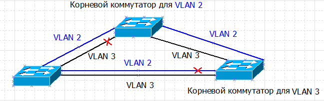
I'll explain now. For example, we have Switch3, which blocks the port to eliminate the loop. Let's take a look at its updated configuration.
Switch3#show spanning-tree VLAN0001 Spanning tree enabled protocol ieee Root ID Priority 32769 Address 0009.7C94.0557 Cost 19 Port 1(FastEthernet0/1) Hello Time 2 sec Max Age 20 sec Forward Delay 15 sec Bridge ID Priority 32769 (priority 32768 sys-id-ext 1) Address 00D0.BA84.7C38 Hello Time 2 sec Max Age 20 sec Forward Delay 15 sec Aging Time 20 Interface Role Sts Cost Prio.Nbr Type ---------------- ---- --- --------- -------- -------------------------------- Fa0/1 Root FWD 19 128.1 P2p Fa0/2 Altn BLK 19 128.2 P2p VLAN0002 Spanning tree enabled protocol ieee Root ID Priority 32770 Address 0009.7C94.0557 Cost 19 Port 1(FastEthernet0/1) Hello Time 2 sec Max Age 20 sec Forward Delay 15 sec Bridge ID Priority 32770 (priority 32768 sys-id-ext 2) Address 00D0.BA84.7C38 Hello Time 2 sec Max Age 20 sec Forward Delay 15 sec Aging Time 20 Interface Role Sts Cost Prio.Nbr Type ---------------- ---- --- --------- -------- -------------------------------- Fa0/1 Root FWD 19 128.1 P2p Fa0/2 Altn BLK 19 128.2 P2p VLAN0003 Spanning tree enabled protocol ieee Root ID Priority 32771 Address 0009.7C94.0557 Cost 19 Port 1(FastEthernet0/1) Hello Time 2 sec Max Age 20 sec Forward Delay 15 sec Bridge ID Priority 32771 (priority 32768 sys-id-ext 3) Address 00D0.BA84.7C38 Hello Time 2 sec Max Age 20 sec Forward Delay 15 sec Aging Time 20 Interface Role Sts Cost Prio.Nbr Type ---------------- ---- --- --------- -------- -------------------------------- Fa0/1 Root FWD 19 128.1 P2p Fa0/2 Altn BLK 19 128.2 P2p We see that it blocks the interface FastEthernet0 / 2 in all 3 VLANs. And now a situation has arisen that you need to make Switch3 the root switch for VLAN 3. As described earlier, a priority game will come to the rescue. Now it is equal to 32771 (32786 + 3). I need to reduce it. This can be done in several ways. The first way is to set the priority manually. I go to Switch 3 and write:
Switch3(config)#spanning-tree vlan 3 priority 30000 % Bridge Priority must be in increments of 4096. % Allowed values are: 0 4096 8192 12288 16384 20480 24576 28672 32768 36864 40960 45056 49152 53248 57344 61440 I decided to set the priority to 30,000, since it is less than 32768. Yes, please note that we are changing the priority without sys-id-ext. But after entering, there is a message that you need to enter a multiple of 4096. And below offers a valid priority. You can enter one of the suggested values and the priority will change.
But I will show another way to change the priority.
Switch3(config)# spanning-tree vlan 3 root primary When you enter this command, the switch looks at what Bridge ID was at the root switch and changes it to a lower value. Only he takes away not 4096, but 8192. That is, he does less by 2 orders of magnitude. I will enter this command and see what changes.
Switch3#show spanning-tree VLAN0001 Spanning tree enabled protocol ieee Root ID Priority 32769 Address 0009.7C94.0557 Cost 19 Port 1(FastEthernet0/1) Hello Time 2 sec Max Age 20 sec Forward Delay 15 sec Bridge ID Priority 32769 (priority 32768 sys-id-ext 1) Address 00D0.BA84.7C38 Hello Time 2 sec Max Age 20 sec Forward Delay 15 sec Aging Time 20 Interface Role Sts Cost Prio.Nbr Type ---------------- ---- --- --------- -------- -------------------------------- Fa0/1 Root FWD 19 128.1 P2p Fa0/2 Altn BLK 19 128.2 P2p VLAN0002 Spanning tree enabled protocol ieee Root ID Priority 32770 Address 0009.7C94.0557 Cost 19 Port 1(FastEthernet0/1) Hello Time 2 sec Max Age 20 sec Forward Delay 15 sec Bridge ID Priority 32770 (priority 32768 sys-id-ext 2) Address 00D0.BA84.7C38 Hello Time 2 sec Max Age 20 sec Forward Delay 15 sec Aging Time 20 Interface Role Sts Cost Prio.Nbr Type ---------------- ---- --- --------- -------- -------------------------------- Fa0/1 Root FWD 19 128.1 P2p Fa0/2 Altn BLK 19 128.2 P2p VLAN0003 Spanning tree enabled protocol ieee Root ID Priority 24579 Address 00D0.BA84.7C38 This bridge is the root Hello Time 2 sec Max Age 20 sec Forward Delay 15 sec Bridge ID Priority 24579 (priority 24576 sys-id-ext 3) Address 00D0.BA84.7C38 Hello Time 2 sec Max Age 20 sec Forward Delay 15 sec Aging Time 20 Interface Role Sts Cost Prio.Nbr Type ---------------- ---- --- --------- -------- -------------------------------- Fa0/1 Desg FWD 19 128.1 P2p Fa0/2 Desg FWD 19 128.2 P2p And I see that the VLAN 3 section has changed. Now there is priority 24579 (24576 + 3) and there is a line “This bridge is the root” indicating that this switch is now root for VLAN 3. Both ports are in “Designated” role and “Forward” status (which is true for the root switch) . But the two upper sections with VLANs remained unchanged and for them FastEthernet 0/2 will remain blocked.
Now let's see how Switch 1 reacted to the fact that they took the crown from him.
Switch1#show spanning-tree VLAN0001 Spanning tree enabled protocol ieee Root ID Priority 32769 Address 0009.7C94.0557 This bridge is the root Hello Time 2 sec Max Age 20 sec Forward Delay 15 sec Bridge ID Priority 32769 (priority 32768 sys-id-ext 1) Address 0009.7C94.0557 Hello Time 2 sec Max Age 20 sec Forward Delay 15 sec Aging Time 20 Interface Role Sts Cost Prio.Nbr Type ---------------- ---- --- --------- -------- -------------------------------- Fa0/2 Desg FWD 19 128.2 P2p Fa0/1 Desg FWD 19 128.1 P2p VLAN0002 Spanning tree enabled protocol ieee Root ID Priority 32770 Address 0009.7C94.0557 This bridge is the root Hello Time 2 sec Max Age 20 sec Forward Delay 15 sec Bridge ID Priority 32770 (priority 32768 sys-id-ext 2) Address 0009.7C94.0557 Hello Time 2 sec Max Age 20 sec Forward Delay 15 sec Aging Time 20 Interface Role Sts Cost Prio.Nbr Type ---------------- ---- --- --------- -------- -------------------------------- Fa0/2 Desg FWD 19 128.2 P2p Fa0/1 Desg FWD 19 128.1 P2p VLAN0003 Spanning tree enabled protocol ieee Root ID Priority 24579 Address 00D0.BA84.7C38 Cost 19 Port 1(FastEthernet0/1) Hello Time 2 sec Max Age 20 sec Forward Delay 15 sec Bridge ID Priority 32771 (priority 32768 sys-id-ext 3) Address 0009.7C94.0557 Hello Time 2 sec Max Age 20 sec Forward Delay 15 sec Aging Time 20 Interface Role Sts Cost Prio.Nbr Type ---------------- ---- --- --------- -------- -------------------------------- Fa0/2 Desg FWD 19 128.2 P2p Fa0/1 Root FWD 19 128.1 P2p We see that he reacted calmly. Switch 1 is still the root for VLAN 1 and VLAN 2. And only for VLAN 3 has it changed its state and port state.
This is how you can manage different STP processes for each of the VLANs. I attach a link to download.
All this is of course good that the switch before turning on the port in every possible way rechecks everything. But if we know that behind the switch port there is a client computer that does not create loops, then we can immediately transfer the port to “Forwarding” mode, without waiting for 30 seconds. For this there is a technology “Portfast”.
I’ll go to Switch2 and use the FastEthernet 0/3 port as an example:
Switch2(config-if)#spanning-tree portfast %Warning: portfast should only be enabled on ports connected to a single host. Connecting hubs, concentrators, switches, bridges, etc... to this interface when portfast is enabled, can cause temporary bridging loops. Use with CAUTION %Portfast has been configured on FastEthernet0/3 but will only have effect when the interface is in a non-trunking mode. After input, it immediately transfers the port to Forwarding mode, but displays a warning that this port must be strictly connected to one user host. Otherwise, when connecting switches and other devices, it can lead to a loop. Under the spoiler below it shows exactly how it works.
Portfast
As you can see, he passed all the stages and immediately switched to the "Forwarding" mode. Do not forget about this technology, but use it with caution, because if there is not a user host, but a switch or other device, you risk creating a loop.
Here is the basic working principle of PVST +. As you can see, it is not much different from the classic STP or CST.
I think you have noticed what kind of text canvas the “show spanning-tree” command displays. And the more VLANs, the more this conclusion. And if you need to look at the information on the switch for the 10th VLAN, you will have to scroll the entire output from the very beginning, until you reach the line with the desired VLAN. To facilitate this situation, there is a very good team that allows you to find out information for a specific VLAN. This is the show spanning-tree vlan X command. I'll check this command.
Switch1#show spanning-tree vlan 3 VLAN0003 Spanning tree enabled protocol ieee Root ID Priority 24579 Address 00D0.BA84.7C38 Cost 19 Port 1(FastEthernet0/1) Hello Time 2 sec Max Age 20 sec Forward Delay 15 sec Bridge ID Priority 32771 (priority 32768 sys-id-ext 3) Address 0009.7C94.0557 Hello Time 2 sec Max Age 20 sec Forward Delay 15 sec Aging Time 20 Interface Role Sts Cost Prio.Nbr Type ---------------- ---- --- --------- -------- -------------------------------- Fa0/2 Desg FWD 19 128.2 P2p Fa0/1 Root FWD 19 128.1 P2p And here he is, at my command, he displays information only for the 3rd VLAN. Very handy command, so take note.
There is another interesting command "show spanning-tree summary".
Switch3#show spanning-tree summary Switch is in pvst mode Root bridge for: VLAN0003 Extended system ID is enabled Portfast Default is disabled PortFast BPDU Guard Default is disabled Portfast BPDU Filter Default is disabled Loopguard Default is disabled EtherChannel misconfig guard is disabled UplinkFast is disabled BackboneFast is disabled Configured Pathcost method used is short Name Blocking Listening Learning Forwarding STP Active ---------------------- -------- --------- -------- ---------- ---------- VLAN0001 1 0 0 1 2 VLAN0002 1 0 0 1 2 VLAN0003 0 0 0 2 2 ---------------------- -------- --------- -------- ---------- ---------- 3 vlans 2 0 0 4 6 It shows summary and brief statistics. In which STP mode the switch works, for which VLAN is it root, what functions are enabled on it. And most importantly, there is a table containing the names of the VLANs and the number of interfaces in this VLAN that are in different states. This is very useful when you need to quickly go in and see if there are any blocked ports on the switch and for which VLANs they are blocked.
In principle, of all the commands, these are often used, and for the CCNA level there are more than enough of them.
In fact, STP and PVST + are not the only loop prevention protocols. There are also RSTP and MSTP. If the MSTP in the CCNA program is practically not mentioned, except for the fact that it exists, then Cisco started to speak openly and in detail about RSTP with Cisco with the new version of the CCNA 3.0 program. Therefore, I will analyze it in more detail.
You probably noticed that the classic STP, that PVST + require time for convergence. Namely, 30 seconds, in case of failure or disconnection of any link. This is certainly not so much, but the larger the network, the longer it takes. And in a large corporate environment, complete convergence can take several minutes. And to resolve this situation, the IEEE committee released the 802.1w standard or RSTP protocol.
What is the essence. If the classic STP had 4 states (Blocking, Listening, Learning, Forwarding), then in RSTP there were fewer of them. Total 3 (Discarding, Listening and Forwarding). That is, the switch drops, learns, or forwards. But it does not converge more quickly because of this. Rapid convergence of the protocol ensures that it calculates in advance which port to turn on if it fails. Thus, in the event of a port failure, he does not start frantically studying the topology and jump over various states, but simply switches to a previously calculated one.
A very good addition to the rapid convergence of the RSTP protocol was left by the user under the nickname ksg222 . And for that I express my gratitude to him. I quote:
Rapid convergence and response to failures in RSTP provide:
- BPDU generation of messages by each device, regardless of the root switch;
- proposal / mechanism, when a point-to-point channel is activated, to quickly move ports to the “Forwarding” state
- the mechanism of using an alternative port, with the loss of communication through the root port (like UplinkFast technology);
- the mechanism of immediate response to receiving BPDU with the “worst” root switch from a neighbor that has designated ports for this network segment (like backbonefast technology);
- a more optimal scheme for sending and processing TCN BPDU messages about changes in the network.
You can enable RSTP using the command:
Switch2(config)#spanning-tree mode rapid-pvst I assembled the lab and turned on the RSTP on each switch and check how quickly the rebuilding of the tree will occur.
RSTP Rebuilding the Tree
As you can see, the rebuild occurs in seconds. For those who want to check it for themselves, I attach a file with a lab.
The article on STP protocols has come to an end. Now we can build STP processes for each VLAN, manage priority and much more. And for the speed of convergence we can use the RSTP protocol.
PS I tried to highlight all the moments, but due to the fact that the article was written for one and a half months at different intervals, I could miss something. If you have something to add, underline or something remains unclear, feel free to write. And even if everything is clear, then write too. I will be pleased! Good luck with your training and see you in the next article.
Source: https://habr.com/ru/post/321132/
All Articles