We start the gas flow rate sensor
Almost a year ago, an article was published with an overview of the sensors of the velocity of the flow of gases and liquids produced by IST-AG.
The last time I had the opportunity onlyon the fingers to explain the basic principle of operation of these elements, but now I am publishing a quite informative story about the FS7 series hot-wire anemometer.
We will start with a theoretical base, and finish the video, where with the help of a bicycle pump and scotch tape, we demonstrate the operation of a prototype FS7-based measuring device.
')

So, all IST flow sensors use the thermal measurement principle - the flow rate is calculated either from the amount of heat that the heated body gives to the flow, or from the difference in readings of two temperature sensors located along the flow symmetrically relative to the heated body.
In the first case, the flow sensor is called hot-wire and does not allow to determine the direction of flow, and in the second case, the sensor is called calorimetric and allows you to determine both the speed and the direction of flow.
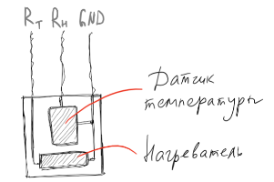
Today we are talking about sensitive elements of the simplest design - about hot-wire sensors. The hot-wire anemometer sensing element consists of a temperature sensor and a heating element.
In the absence of flow, the temperature of the heater remains unchanged,
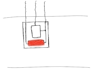
and in the presence of flow, the heater begins to give its heat to the environment.
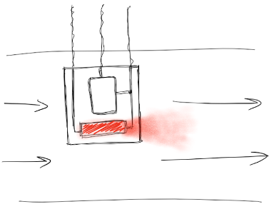
The amount of heat that is given to the flow by the heated element depends on the thermophysical characteristics of the medium, on the parameters of the pipe and on the velocity of the flow. For applications where the characteristics of the medium and the dimensions of the pipe are known, the heat output of the heater can be used to calculate the flow rate.
Both the temperature sensor and the heater are platinum thermal resistances - elements whose resistance is almost linearly dependent on the temperature of the medium.
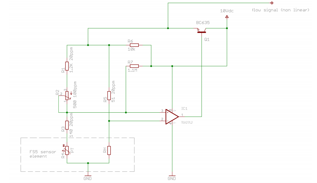
Both thermistors are included in the bridge circuit, which in the absence of flow is balanced. As the flow rate increases, the heater cools, its resistance changes, and the bridge will unbalance. The unbalance signal is fed to the amplifier, the output signal of the amplifier informs the heater of a higher temperature and brings the bridge back into equilibrium. The magnitude of the voltage required to balance the bridge is a function of the flow velocity.

The production process of IST flow rate sensors is very similar to the production of conventional thermal resistances (temperature sensors). I refer to the article devoted to the production of thin-film thermistors a little higher.
On a ceramic substrate with low thermal conductivity, platinum meanders are deposited - conductive paths from which two thermal resistors are formed.
The first thermal resistance - the heater - has a nominal resistance R0 = 45 Ohm, the second - a temperature sensor - has a nominal resistance R0 = 1200 Ohm.

The substrate also contains the necessary connections and contact pads for fastening the leads. The design on both sides is covered with a passivation layer of glass, after which the leads are attached to the sensor.
I see no reason to delve into physics and analyze the derivation of the formula for calculating the flow rate, I will only note the basic laws on which this formula is based.
1. The heat balance equation - the dependence of the amount of heat which the heater gave to the medium, on the temperature difference between the heater and the medium heater surface area and heat transfer coefficient of the heater .
2. King’s law relating the amount of heat to the instantaneous flow rate
where
The formula for calculating the flow rate in which the FS7 element is placed is the result of transformations and simplifications of King’s law. The formula is as follows:
- voltage in the absence of flow (value reflects - the initial difference between the temperature of the heater and the temperature of the medium)
- coefficient that depends on the flow profile and on the position of the sensor; value belongs to the range (0.9 ... 0.93)
- coefficient for FS7 sensors equal to 0.51
- desired flow rate
The work also uses the reverse formula .
Coefficients and are selected during sensor calibration (see below).
The FS7 sensor has three outputs: heater contact, temperature sensor contact, and ground.
There is no universal circuit for switching on the sensor, as well as detailed recommendations for its installation. The reason is obvious - the ratio of the flow rate to voltage depends not only on the geometry of the sensitive element, but also on the environmental parameters (temperature, composition, pressure, the presence of mechanical particles), as well as on the geometry of the pipe, the position of the sensor in the pipe and the flow profile. In each specific task, this set of parameters will be different, so the selection of nominal values for the inclusion scheme and the calculation of coefficients for calculating the flow velocity are selected for each task separately.
However, you always need to make a start from something, in this case it is best to push off from the scheme given in the FS7 documentation:
An example of the dependence of the output voltage on the flow rate:
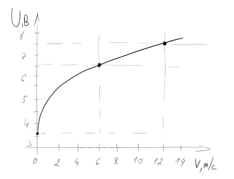
Three points are used to calibrate the sensor - zero speed, maximum flow rate and point in the middle.
In the absence of a stream, the value is fixed . Let be AT.
With In and m / c formula takes the form .
With In at m / c formula takes the form
We obtain a system of two equations with two unknowns, from which we find and .
Substituting values , and stress in the formula , we get a simple expression to calculate the flow rate.
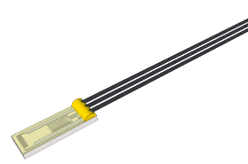
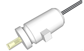
Three standard versions of the FS7 sensor are available, which differ from each other in the presence of a round plastic case and an operating temperature range.
At the stage of familiarization with the FS7 series sensors, you can also use the ready-made FS-Flowmodul module, which incorporates the switching circuit.
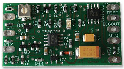
The FS-Flowmodul has three contacts for connecting the FS7 sensor on one side and the Power, Earth and Output contacts on the other side. Among other things, the board is equipped with a potentiometer for adjusting the output voltage (see resistor R2 in the wiring diagram).
It is important to note that the module is not intended for use in serial devices. The board can only be used at the prototyping stage, when it is easier for someone to assemble the circuit on their own, and it’s more convenient for someone to pay me 108 euros and get a ready-made debugging fee :)
Naturally, the easiest way was chosen to demonstrate the performance of the sensor. The sensor is connected to FS-Flowmodul, and the output of the module is connected to the ADC input on the control board.
The debug board is based on the SiLabs microcontroller and is connected to the Riverdi touchscreen TFT display.
The process of creating a program to display information on this display was devoted to as many as five articles on Habré . Now, a module for measuring the flow rate has been added to the previously described prototype for measuring temperature and humidity.
Incidentally, when we show this prototype alive, to demonstrate the operation of the sensors on them, it is enough just to blow - from breathing, both humidity and temperature and flow rate increase at the same time. Unfortunately, this process cannot be beautifully captured on video, so the HYT-271 sensor was shown on a boiling pot, and for FS7 we had to build a makeshift air duct from the tube for aquarium aperture, into which air is pumped using a bicycle pump.
Important: the sensor must be installed in the center of the pipe diameter, working surface exactly along the direction of flow.
In conclusion, I traditionally thank the reader for his attention and remind you that questions about the use of products, about which we write on Habré, can also be asked by email, specified in my profile.
upd: all mentioned sensors and modules are available from stock. More information on efo-sensor.ru
The last time I had the opportunity only
We will start with a theoretical base, and finish the video, where with the help of a bicycle pump and scotch tape, we demonstrate the operation of a prototype FS7-based measuring device.
')
So, all IST flow sensors use the thermal measurement principle - the flow rate is calculated either from the amount of heat that the heated body gives to the flow, or from the difference in readings of two temperature sensors located along the flow symmetrically relative to the heated body.
In the first case, the flow sensor is called hot-wire and does not allow to determine the direction of flow, and in the second case, the sensor is called calorimetric and allows you to determine both the speed and the direction of flow.
The principle of operation of the thermoanemometric sensor
Today we are talking about sensitive elements of the simplest design - about hot-wire sensors. The hot-wire anemometer sensing element consists of a temperature sensor and a heating element.
In the absence of flow, the temperature of the heater remains unchanged,
and in the presence of flow, the heater begins to give its heat to the environment.
The amount of heat that is given to the flow by the heated element depends on the thermophysical characteristics of the medium, on the parameters of the pipe and on the velocity of the flow. For applications where the characteristics of the medium and the dimensions of the pipe are known, the heat output of the heater can be used to calculate the flow rate.
Both the temperature sensor and the heater are platinum thermal resistances - elements whose resistance is almost linearly dependent on the temperature of the medium.
All you need to know thermistors - in the articles " Thermal Resistance: Theory " and " Thermal Resistance: Production Process "
Both thermistors are included in the bridge circuit, which in the absence of flow is balanced. As the flow rate increases, the heater cools, its resistance changes, and the bridge will unbalance. The unbalance signal is fed to the amplifier, the output signal of the amplifier informs the heater of a higher temperature and brings the bridge back into equilibrium. The magnitude of the voltage required to balance the bridge is a function of the flow velocity.
Sensor structure
The production process of IST flow rate sensors is very similar to the production of conventional thermal resistances (temperature sensors). I refer to the article devoted to the production of thin-film thermistors a little higher.
On a ceramic substrate with low thermal conductivity, platinum meanders are deposited - conductive paths from which two thermal resistors are formed.
The first thermal resistance - the heater - has a nominal resistance R0 = 45 Ohm, the second - a temperature sensor - has a nominal resistance R0 = 1200 Ohm.
The substrate also contains the necessary connections and contact pads for fastening the leads. The design on both sides is covered with a passivation layer of glass, after which the leads are attached to the sensor.
The formula for calculating the flow rate
I see no reason to delve into physics and analyze the derivation of the formula for calculating the flow rate, I will only note the basic laws on which this formula is based.
1. The heat balance equation - the dependence of the amount of heat which the heater gave to the medium, on the temperature difference between the heater and the medium heater surface area and heat transfer coefficient of the heater .
2. King’s law relating the amount of heat to the instantaneous flow rate
where
The formula for calculating the flow rate in which the FS7 element is placed is the result of transformations and simplifications of King’s law. The formula is as follows:
- output voltage of the circuit
- voltage in the absence of flow (value reflects - the initial difference between the temperature of the heater and the temperature of the medium)
- coefficient that depends on the flow profile and on the position of the sensor; value belongs to the range (0.9 ... 0.93)
- coefficient for FS7 sensors equal to 0.51
- desired flow rate
The work also uses the reverse formula .
Coefficients and are selected during sensor calibration (see below).
Sensor wiring diagram
The FS7 sensor has three outputs: heater contact, temperature sensor contact, and ground.
There is no universal circuit for switching on the sensor, as well as detailed recommendations for its installation. The reason is obvious - the ratio of the flow rate to voltage depends not only on the geometry of the sensitive element, but also on the environmental parameters (temperature, composition, pressure, the presence of mechanical particles), as well as on the geometry of the pipe, the position of the sensor in the pipe and the flow profile. In each specific task, this set of parameters will be different, so the selection of nominal values for the inclusion scheme and the calculation of coefficients for calculating the flow velocity are selected for each task separately.
However, you always need to make a start from something, in this case it is best to push off from the scheme given in the FS7 documentation:
An example of the dependence of the output voltage on the flow rate:
Three points are used to calibrate the sensor - zero speed, maximum flow rate and point in the middle.
In the absence of a stream, the value is fixed . Let be AT.
With In and m / c formula takes the form .
With In at m / c formula takes the form
We obtain a system of two equations with two unknowns, from which we find and .
Substituting values , and stress in the formula , we get a simple expression to calculate the flow rate.
FS7 sensor types and FS-flowmodul module
Three standard versions of the FS7 sensor are available, which differ from each other in the presence of a round plastic case and an operating temperature range.
| FS7.0.1L.195 | FS7.0.4W.015 | FS7.A.1L.195 | |
| Measuring range | 0 ... 100 m / s | ||
| Resolution | 0.01 m / s | ||
| Response time | ~ 200 ms | ||
| Operating temperature range | −20 ... +150 ° C | −20… +400 ° C | −20 ... +150 ° C |
| Item Dimensions | 6.9 x 2.4 mm | ||
| findings | insulated 195 mm long | not isolated 15 mm long | insulated 195 mm long |
| Body dimensions | - | Ø 6 mm, length 14 mm | |
| Retail price | UPD of July 4, 2017: 16 EUR | 21.29 EUR | 25,44 EUR |
At the stage of familiarization with the FS7 series sensors, you can also use the ready-made FS-Flowmodul module, which incorporates the switching circuit.
The FS-Flowmodul has three contacts for connecting the FS7 sensor on one side and the Power, Earth and Output contacts on the other side. Among other things, the board is equipped with a potentiometer for adjusting the output voltage (see resistor R2 in the wiring diagram).
It is important to note that the module is not intended for use in serial devices. The board can only be used at the prototyping stage, when it is easier for someone to assemble the circuit on their own, and it’s more convenient for someone to pay me 108 euros and get a ready-made debugging fee :)
Demonstration
Naturally, the easiest way was chosen to demonstrate the performance of the sensor. The sensor is connected to FS-Flowmodul, and the output of the module is connected to the ADC input on the control board.
The debug board is based on the SiLabs microcontroller and is connected to the Riverdi touchscreen TFT display.
The process of creating a program to display information on this display was devoted to as many as five articles on Habré . Now, a module for measuring the flow rate has been added to the previously described prototype for measuring temperature and humidity.
Incidentally, when we show this prototype alive, to demonstrate the operation of the sensors on them, it is enough just to blow - from breathing, both humidity and temperature and flow rate increase at the same time. Unfortunately, this process cannot be beautifully captured on video, so the HYT-271 sensor was shown on a boiling pot, and for FS7 we had to build a makeshift air duct from the tube for aquarium aperture, into which air is pumped using a bicycle pump.
Important: the sensor must be installed in the center of the pipe diameter, working surface exactly along the direction of flow.
Notes
- I admit some simplifications when describing the description of physical phenomena that should be taken into account in the practice of working with flow sensors. The purpose of today's publication is to demonstrate the basic principles of operation of FS7 sensitive elements. However, if there are commentators who are ready to reveal the physics of the process in more detail, such explanations will be accepted by the author with gratitude, expressed in the discount on the purchase of FS7.
- All information that can be found on the Internet for the flow sensor FS5 is also relevant for the FS7 sensor. First of all, I recommend Application Note FS5 and an article in which, among other things, there is a stream profile description.
Conclusion
In conclusion, I traditionally thank the reader for his attention and remind you that questions about the use of products, about which we write on Habré, can also be asked by email, specified in my profile.
upd: all mentioned sensors and modules are available from stock. More information on efo-sensor.ru
Source: https://habr.com/ru/post/321108/
All Articles